F14: Team5-Self Driving Car - AUG
Contents
- 1 Self Driving Car
- 2 Objective and Scope
- 3 Team Members & Responsibilities
- 4 Introduction
- 5 Schedule
- 6 Parts List & Cost
- 7 Backup Parts & cost
- 8 Design & Implementation
- 9 Motor Controller
- 10 Sensor Controller
- 11 Central Controller
- 12 Geographical Controller
- 13 IO Controller
- 14 Communication (Bluetooth & Android) controller
- 15 Controller Communication Table
- 16 Testing & Technical Challenges
- 17 Future Enhancement
- 18 Project Video
- 19 Project Source Code
- 20 References
Self Driving Car
Objective and Scope
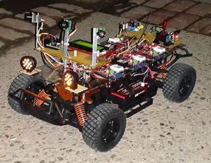
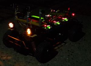
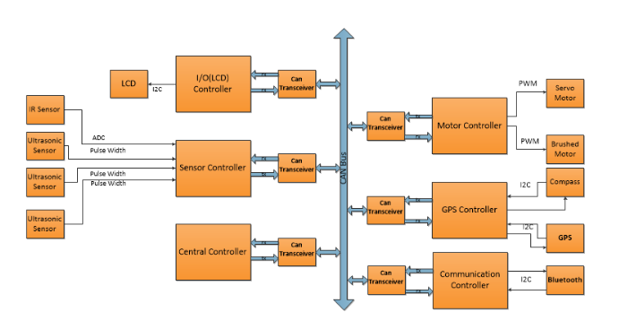
This project is aimed at building a self-driving car with obstacle avoidance and to steer to the GPS location pointed by the android application with the help of multiple controllers communicating using CAN bus. CAN(Control Area Network) is a communication protocol used widely in automotive application developed by BOSCH in 1986. The self-driving car consists of 6 different controllers for GPS,Sensor,Central,Motor,IO and Communication. The controllers communicate with each other using CAN bus. We have implemented broadcast algorithm to broadcast all the data from each controller using different message identifiers. The controller parses the data using the 29 bit identifier which has destination and source address.
Team Members & Responsibilities
| Sl. No | Task | Team Members |
|---|---|---|
| 1 | Sensor Controller |
|
| 2 | Motor Controller |
|
| 3 | I/O Controller (LCD Display) |
|
| 4 | Communication Bridge + Android |
|
| 5 | Geographical Controller |
|
| 6 | Central Controller |
|
| 7 | Car design and wiring |
|
| 8 | Git Setup | Akash Ayare |
Introduction
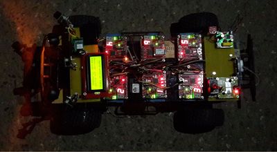
The goal of this project was to design and implement a self-driving car. The team consisted of 15 people, divided into 6 teams corresponding to six controllers. The aim of this class was to understand the CAN protocol that is used extensively in vehicles. The self-driving car houses six controllers, all of them communicating using CAN. Each controller performs a unique task such as:
- Sensor Controller: Interfaced to the front and back sensors. Periodically sends sensor data to the central controller. Crucial for obstacle detection and avoidance
- Motor Controller: Controls the motors and steering of the car, based on commands received from central controller.
- Geographical Controller: Interfaced to GPS and compass. Periodically sends location, heading and distance from destination. crucial for autonomous navigation of the car.
- Communication Controller: Acts as a bridge for Android. Android app is used to set destination, calculate path to destination, start and stop the car. Data is sent to central and geographical Controller based on user input.
- Central Controller: The brain of the car. Uses sensor and geographical data to steer the car in the right direction. Uses sensor data to detect and avoid obstacles. Uses geographical data to move towards desired location
- Display Controller: Interfaced to an LCD screen which displays status of the car (reached/ not reached), CAN bus utilization, sensor data, bearing, heading etc.
Detailed explanation of the project is provided here: Car Demo
Schedule
Geographical Controller
| Sl. No | Start Date | End Date | Task | Status | Actual Completion Date |
|---|---|---|---|---|---|
| 1 | 1-Oct-2014 | 14-Oct-2014 | Order Components and Make a schedule | Completed | 14-Oct-2014 |
| 2 | 8-Oct-2014 | 14-Oct-2014 | Decide commands that Geographical Controller will support | Completed | 14-Oct-2014 |
| 3 | 7-Oct-2014 | 14-Oct-2014 | Complete CAN RX task and subscription handling. Verify communication with other controllers | Completed | 21-Oct-2014 |
| 4 | 14-Oct-2014 | 24-Oct-2014 | Interface GPS module and Compass and develop drivers if needed | Completed | 28-Oct-2014 |
| 5 | 24-Oct-2014 | 30-Oct-2014 | Design and develop algorithm to calculate heading and bearing from GPS coordinates | Completed. | 30-Oct-2014 |
| 6 | 24-Oct-2014 | 5-Nov-2014 | Work on calibration of compass and heading calculation | Completed | 11-Dec-2014 |
| 7 | 1-Nov-2014 | 10-Nov-2014 | Test with the central and Bluetooth controller | Completed | 14-Dec-2014 |
| 8 | 10-Nov-2014 | 25-Nov-2014 | Begin testing with fully assembled car | Completed | 1-Dec-2014 |
| 9 | 25-Nov-2014 | 10-Dec-2014 | Final Testing and changes as needed | Completed | 19-Dec-2014 |
Sensor Controller
| Sl. No | Start Date | End Date | Task | Status | Actual Completion Date |
|---|---|---|---|---|---|
| 1 | 10/3/2014 | 10/10/2014 | Order ultrasonic sensor parts and develop simple test code for the sensors | Done | 10/10/2014 |
| 2 | 10/10/2014 | 10/17/2014 | Wire the ultrasonic sensors, develop and implement the sensors using analog to digital converter | Done | 10/17/2014 |
| 3 | 10/17/2014 | 10/24/2014 | Collaborate with the other sub teams to finish the CAN bus communication and allow the self driving car to drive autonomously | Done | 10/24/2014 |
| 4 | 10/24/2014 | 11/1/2014 | Develop, implement and test the ultrasonic sensors using the pulse width modulation and universal asynchronous receiver/transmitter | Done | 11/1/2014 |
| 5 | 11/2/2014 | 11/9/2014 | Develop, implement and test the front and back infrared sensors using analog to digital converter | Done | 11/9/2014 |
| 6 | 11/10/2014 | 11/17/2014 | Develop, implement and test the current/voltage sensor for the battery packs of the self driving car using I2C | Scheduled | Removed |
| 7 | 11/18/2014 | 11/25/2014 | Collaborate with the other sub teams to make sure that the sensors are in working condition | Done | 11/25/2014 |
| 8 | 11/26/2014 | 12/5/2014 | Collaborate with the other sub teams to debug any problems that may encountered | Done | 12/5/2014 |
| 9 | 12/6/2014 | 12/13/2014 | Prepare for demo | Done | 12/19/2014 |
IO Controller
| Sl. No | Start Date | End Date | Task | Status | Actual Completion Date |
|---|---|---|---|---|---|
| 1 | 10/7/2014 | 10/14/2014 | Research and order LCD appropriate for this project | Done | 10/11/2014 |
| 2 | 10/7/2014 | 10/17/2014 | Implement CAN RX/Subscription task | Done | 10/13/2014 |
| 3 | 10/7/2014 | 10/17/2014 | Finalize Task Architecture | Done | 11/1/2014 |
| 4 | 10/18/2014 | 10/21/2014 | Interface and test LCD | Done | 10/20/2014 |
| 5 | 10/21/2014 | 10/28/2014 | Implement auto scrolling feature | Done | 11/18/2014 |
Communication Bridge + Android
| Sl. No | Start Date | End Date | Task | Status | Actual Completion Date |
|---|---|---|---|---|---|
| 1 | 16-Sep-2014 | 23-Sep-2014 | Test bluetooth module using computer serial port and an android app(simple bluetooth terminal app downloaded from google play). Test the real life range and stability of the bluetooth module (HC-06). Modify the bluetooth chat example to work with the bluetooth module. | Done | 20-Sep-2014 |
| 2 | 28-Sep-2014 | 12-Oct-2014 | Draw UI design layouts for a basic android application that can view Google map as well as send GPS data through bluetooth by clicking on the map. Study google maps API and make a simple app that will post a short toast that shows the GPS location after a long press event. | Done | 12-Oct-2014 |
| 3 | 7-Oct-2014 | 11-Oct-2014 | Interface bluetooth module with SJSUOne board and able to verify that the connection is stable and that transaction via the bluetooth is accurate. This is done by adding a test button where if you press the button it send a command to the board. After receiving the command, the board should react with a response (LED light and/or text response to the android phone) | Done | 19-Oct-2014 |
| 4 | 11-Oct-2014 | 19-Oct-2014 | Integrate Google Maps and Bluetooth component together in Android app. After a long press on the map, the user should be prompted to start the car and set the location as the places the user selected. Add a textView to display the location selected by pressing on the map. Add a button for sending location to the car. | Done | 27-Oct-2014 |
| 5 | 19-Oct-2014 | 26-Oct-2014 | CAN infrastructure implmentation: Use our team's common CAN infrasturcture code and modify it specifically for our controller. First created the CAN communication table and then modify the infracturacture code to implement the broacasting as well as filtering of neccessary data. This only focuses on broadcasting a stop/start command and the destination GPS data (set by android) as well as getting car's current location data from the geological controller. | Done | 07-Nov-2014 |
| 6 | 26-Oct-2014 | 1-Nov-2014 | Test and implement car information reading as well as other functions of Android app | Done | |
| 7 | 2-Nov-2014 | 4-Nov-2014 | Iterate UI design | Done | |
| 8 | 5-Nov-2014 | 16-Nov-2014 | Implement 2nd UI design | Done |
Motor Controller
| Sl. No | Start Date | End Date | Task | Status | Actual Completion Date |
|---|---|---|---|---|---|
| 1 | 10/1/2014 | 10/8/2014 | PWM2 (used to control motors) and PWM3 (used to control servo) interface with the car servo and motor. Write a test code to operate the servo and motor from the terminal command. | Completed and Tested | 10/11/2014 |
| 2 | 10/9/2014 | 10/18/2014 | Design and code CAN receive task for subscription. Check for basic CAN message commands for throttle and steer control. | Completed and tested | 10/26/2014 |
| 3 | 10/19/2014 | 10/28/2014 | Design the CAN message table for motor control and servo control | Completed and tested | 10/26/2014 |
| 4 | 10/29/2014 | 11/07/2014 | Design acceleration Vs steer control function for smooth run. Check for other factors involved. | Completed and tested | 11/22/2014 |
| 5 | 11/08/2014 | 11/14/2014 | Research on RPM sensor. Interface the RPM sensor to calculate the Speed. Test the RPM sensor by running the car at different speed | Completed and tested with a hall sensor | 11/22/2014 |
| 6 | 11/15/2014 | 11/21/2014 | Fine tune motor control code and integrate with all the controllers for proper working. | Completed and tested | 11/22/2014 |
| 7 | 11/22/2014 | 11/28/2014 | Test and check if more features can be added to improve performance. Completed and tested | Completed and tested | 11/28/2014 |
| 8 | 11/29/2014 | 12/05/2014 | Testing and Debugging. | Completed and tested | 12/05/2014 |
| 9 | 12/06/2014 | 12/18/2014 | Final Testing and getting the car ready for Demo. | Completed |
Central Controller
| Sl. No | Start Date | End Date | Task | Status |
|---|---|---|---|---|
| 1 | 16-Sep-2014 | 23-Sep-2014 | Develop API for CAN bus communication. | Done |
| 2 | 11-Oct-2014 | 15-Oct-2014 | Develop communication table for all controllers. | Done |
| 3 | 15-Oct-2014 | 20-Oct-2014 | Broadcast message and target message setup. | Done |
| 4 | 21-Oct-2014 | 28-Oct-2014 | Co-ordinate all controllers and take major decisions. | Done |
| 5 | 28-Oct-2014 | 11-Nov-2014 | Complete Building and fine-tuning of RC car. | Done |
| 6 | 21-Oct-2014 | 11-Nov-2014 | Develop coordination mechanism to ensure controllers are initialized and ready | Done |
| 7 | 21-Oct-2014 | 28-Oct-2014 | Develop kill switch | Done |
| 8 | 14-Oct-2014 | 21-Oct-2014 | Build external power distribution circuit | Done |
| 9 | 28-Oct-2014 | 04-Nov-2014 | Coordination algorithm between steering and throttle for smooth turns | Done |
| 10 | 04-Nov-2014 | 11-Nov-2014 | Collision avoidance algorithms | Done |
| 11 | 04-Nov-2014 | 11-Nov-2014 | Intermediate unit and functional tests | Done |
| 12 | 11-Nov-2014 | 25-Nov-2014 | Functional tests and algorithm adjustments | Done |
| 13 | 25-Nov-2014 | 02-Dec-2014 | Fine tuning and stretch goals (headlights, parallel parking, etc.) | Done |
| 14 | 02-Dec-2014 | 09-Dec-2014 | Prepare for demo | Done |
Parts List & Cost
| Description | Qty | Price |
|---|---|---|
| LV-MaxSonar-EZ1 High Performance Ultrasonic Rangefinder | 2 | 49.90 |
| Analog Distance Sensor | 1 | Free |
| 1/10 Scale 4x4 Truck with Brushed Motor | 1 | 217.33 |
| 2 ft 12-Gauge Power Cables | 3 | 22.80 |
| Pair Power Socket | 2 | 2.16 |
| Standard Size Body Clips | 12 | 2.16 |
| 4-pack AA Batteries | 1 | 3.45 |
| 50-pack M3x15mm Stand-Off Spacer Female-Male | 1 | 11.19 |
| 100-pack 18-8 Flat Steel Washer | 1 | 2.54 |
| 100-pack M3x20mm Hex-Drive Screw | 1 | 6.47 |
| 100-pack M3 Steel Hex Nut | 1 | 4.66 |
| 2-pin JST Connector Right Angle | 10 | 6.84 |
| 4-pin JST Connector Right Angle | 10 | 6.84 |
| 2-pin Female JST Cable (20 cm) | 10 | 7.39 |
| 4-pin Female JST Cable (20 cm) | 10 | 7.39 |
| 5 Volt Relay Breakout Board | 1 | 4.95 |
| 5 Volt Voltage Regulator | 1 | 1.07 |
| Sharp Analog Distance Sensor 4-30 cm | 1 | 9.95 |
| 3-pin Female JST PH-Style Cable (30 cm) | 1 | 0.92 |
| Double Sided Mounting Tape - 3 feet | 1 | 4.35 |
| AC Adapter (LiPo Charger) | 1 | 15.16 |
| IEC Power Cable (LiPo Charger) | 1 | 5.38 |
| 4mm Bullet Plugs to Universal Plug | 1 | 13.38 |
| Acrylic sheet + Sharpe mini | 1+1 | 11.72 |
| Molex Pin Header, Connector, wires and 100 zip ties | 10+4+1 | 17.13 |
| 2 x 90 degree pin header, 2 x straight pin header | 2+2 | 3.65 |
| uni-polar hall sensor for tachometer feedback | 2 | 2.18 |
| Heavy Duty magnets | 2 | 4.18 |
| INA219 Voltage sensors 26V +/-3.2A | 2 | 19.9 |
| 20x4 Serial LCD Module | 1 | 29.99 |
Backup Parts & cost
| Qty | Description | Manufacturer | Part Number | Total Cost |
|---|---|---|---|---|
| 1 | LV-MaxSonar-EZ1 High Performance Ultrasonic Rangefinder | MaxBotix Inc | MB1010 | Free |
| 1 | Analog Distance Sensor | Sharp | Free |
Design & Implementation
Motor Controller
Summary
This module takes command input from central controller and steers the car to its destination; in addition, It has two main controlling parameters : Throttle and Steering. Throttle input moves the car forward and backward. Steer input turns the wheel left and right. The central controller takes feedback from the sensors and makes decision to move the car. Accordingly, it sends CAN commands accepted by the motor controller for navigation, and real time RPM signal to the controller.
| Sl.No | Controller | Signal Type | Frequency | Functionality |
|---|---|---|---|---|
| 1 | Motor Control | PWM signal | 50 Hz (20000us) | 1000us (Full throttle forward) - 1500us (Stop) - 2000us (Full throttle backward) |
| 2 | Steer Control | PWM signal | 50 Hz (20000us) | 1000us (Turn left max) - 1500us (Center) - 2000us (Turn right max) |
Block Diagram
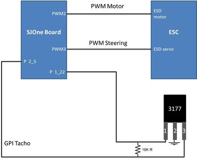
The following Block diagram shows an overview of the connection between the SJOne board, ESC, and the Hall sensor:
Working
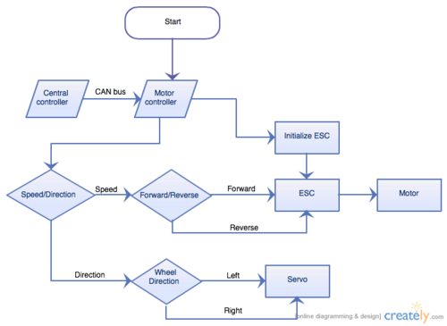
The car initially accepts the start command to begin navigation. Commands can then come to move the car forward or backward, steer left or right depending on intelligent decisions made by the central controller. The motor control has intelligence to avoid jerks and ensure smoother transitions between commands. The central controller gets the data from the sensors for obstacle avoidance. The car has a communication controller which gets the GPS data from the android application, the android application sets the destination latitude and longitude. The car decides the heading direction by the gps points and the compass and if it finds obstacle it will be controlled by the obstetrical avoidance and steer to the destination according to the algorithm below.
Kill switch
The remote control and receiver module pair up to provide a signal coverage of more than 100 meters. We make use of this to design our kill switch. When a constant PWM signal of 1000us is received from the remote, the car is in 'ARMED' state and moves the car according to CAN commands. The user has to hold the trigger gun for this state constantly and the car moves. When the user releases the trigger gun, the car stops receiving the PWM signal of 1000us and the car goes to 'DISARMED' state. In short, pull the trigger gun - ARMED, release the trigger gun - DISARMED.
RPM
The RPM sensor is based on a hall sensor switch which detect the North and South pole of a magnet located in the main shaft in the car. The hall sensor part number is 3177, and it has three pin. This sensor is uni-polar which give an output high signal when the sensor captures the North pole of the magnet; subsequently, the sensor give output low signal when the sensor captures the South pole of the magnet. Therefore, by using a the 3177 and a magnet in the shaft. the SJOne board can capture the output signal from the hall sensor as it toggles per shaft revolution. It is important to notice that the output signal of the 3177 is an open collector; therefore, we need a 10 Kohm resistor connected to Vcc.
Pinout Table
The following table shows the pinout of all component that are connected to SJONE board.
| No | Description | Component Pin | Output Pin Source |
|---|---|---|---|
| 1 | Hall Sensor (3177) Vcc ( 4.5 V to 18 V) | Source | SJOne P1_22 |
| 2 | Hall Sensor (3177) Ground | Ground | SJOne |
| 3 | Hall Sensor (3177) Output | Output | SJOne P1_22 with a 10 KOhm |
| 4 | CAN Transceiver | Pin # 1 TX | SJOne P0_1(Tx) |
| 5 | CAN Transceiver | Pin # 2 GND | SJOne GND |
| 6 | CAN Transceiver | Pin # 3 VCC | SJOne 3.3v |
| 7 | CAN Transceiver | Pin # 4 RX | SJOne P0_0(Rx) |
| 8 | CAN Transceiver | Pin # 6 CANL | CAN Bus |
| 10 | CAN Transceiver | Pin # 7 CANH | CAN Bus |
| 11 | Servo | VCC | 5V Power Rail |
| 12 | Servo | GND | GND Power Rail |
| 13 | Servo | Signal | PWM 2.1 |
| 14 | Electric Speed Control (ESC) | VCC | 5V Power rail |
| 15 | Electric Speed Control (ESC) | GND | GND Power Rail |
| 16 | Electric Speed Control (ESC) | Signal | PWM 2.2 |
Sensor Controller
Sensor Controller Hardware Design and Architecture
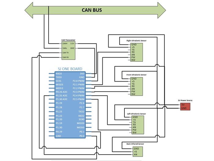
The figure below shows how all the sensors are inter-connected to the SJOne board and CAN bus. The sensors are connected to +5V to achieve the highest beam pattern that is available. The back infrared sensor is also connected to the +5V power source to obtain the longest range detection possible. Most important, the SJOne board is connected to the CAN bus to broadcast the available data to the rest of the controllers in the system.
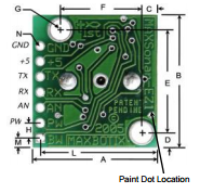
When using multiple MaxSonar sensors, it is required to configure the sensors in Sequential Operation mode to obtain the best optimal performance in obstacle detection. On the other hand, if the sensors are left in continuous free run operation, which means the RX pin (Pin 4) are unconnected then at start-up the sensors will range at exactly the same time. Thus, the sensors are not synchronized and eventually result in frequency drifts that would likely cause interference between sensors for most applications.
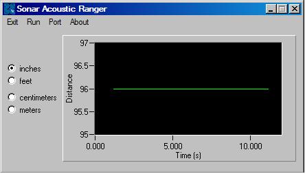
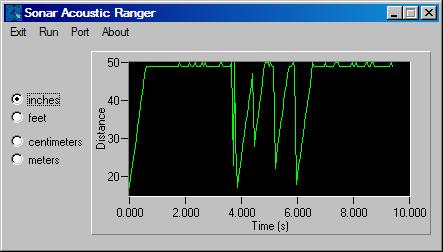
The figure to the above shows a single MaxSonar ultrasonic sensor operating in continuous free run operation detecting an object at 96 inches. The signal of the ultrasonic sensor observe under the oscilloscope shows that the sensor is operating at its finesse performance without any interference.
The figure to the below shows that multiple MaxSonar ultrasonic sensors are operating in continuous free run operation. As you can see, the signal of a ultrasonic sensor observe under the oscilloscope shows that the signal has multiple spikes due to the interference of other sensors. Thus, the sensor becomes unsynchronized and the range reading become unstable.
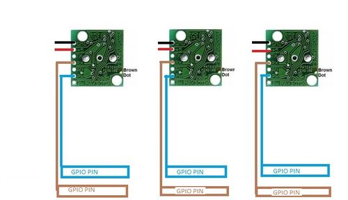
To achieve the most optimal performance using multiple MaxSonar ultrasonic sensors, the figure below shows the implementation of all the sensors operating in sequential mode. The sensors can be started by pulling the RX pin (Pin 4) high for at least 20 uS and then for each reading this can be done as often as every 50 ms. This method would toggle each sensor when the user like to obtain an reading at any given moment. Thus, there will be no interference between each sensor.
There are many other method to implement multiple MaxSonar ultrasonic sensors in a single system. This information can be obtained in the sensor datasheet.
Sensor Controller Software Design
The sensor controller interfaces three ultrasonic sensors using pulse width and one infrared back sensor using ADC. The pin mappings are shown in the Sensor Controller Hardware Design figure above. Each of the front sensors were connected to two GPIO's, one to check the pulse width and one for toggling the sensors individually to minimize beam interference.
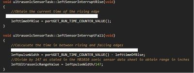
We configured the GPIO's used to calculate pulse width for the falling and rising edge interrupts as shown in the figure above using the API available from the eint header file available with the source code provided as the part of the class package. The functions associated with the rise and fall interrupts were used to calculate the time of flight(ToF), which was the time required for the ultrasonic beam to reach back to the sensor. The final distance value was calculated using the following equation:-
ultraSonicSensorVal = ToF/147;
The figure above shows the software implementation of the equation mentioned above. At the same time, the equation was used from the sensor datasheet attached in the references section at the end of the report. The values were sampled and averaged to reduce the effect of incorrect readings.
The infrared back sensor has a range of 10-80 cms and was interfaced using the on-board ADC. The back sensors value(in inches) was derived using the following equation:-
backSensorReading = 4800/(ADCVal- 20))/2.54);
The CAN messages were updated periodically with the new values at 20Hz frequency. The updates took place inside a critical section to avoid corruption in values due to task switching or other unseen causes. These values were broadcasted on the CAN bus and used by the central controller to make driving decisions based on other inputs and to command the motor controller accordingly.
Central Controller
The central controller is the brain of the car. It receives information from all the other controllers and decides which direction the car must move. The central controller periodically sends commands to the motor regarding the throttle, steering, steering angle and speed.
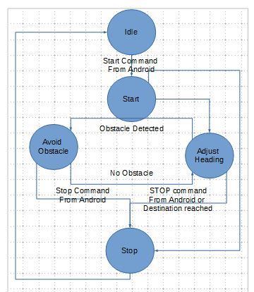
In order to decide which direction to move, the central controller uses sensor data and geographical data. The current design uses a state machine. The car is initially in idle state. When it received a START command from the communication controller, the central sends the start motor command to the motor controller. After the start state, the central controller can be in one of the two states: avoid obstacle or adjust heading. The central controller uses the sensor data to detect obstacle. If there are no obstacles, then the central controller uses geographical information to adjust car heading.
Once the heading and bearing match, the car moves straight ahead till the destination is reached. When the geographical controller sends a command indicating that the car has reached the destination, the car will stop.
At any point during its course, if the car receives a STOP command from the communication controller, the car will stop
Geographical Controller
The geographical controller is one of the six controllers mounted on the car. This controller provides the location and heading information to the central controller of the car. It also stores the destination (way-points). By calculating the distance from the current location to the destination or intermediate waypoint, the geo controller can determine if the car has reached its destination. When the car reaches the destination, the geo controller sends a message to the central controller indicating that destination has been reached.
The devices connected to this controller are: 1. Magnetometer (digital compass) 2. GPS Logger
The compass communicates via I2C and the GPS via UART.
Parts Used
| Part Number | Purpose |
|---|---|
| SparkFun Triple Axis Magnetometer Breakout - HMC5883L | Compass |
| SparkFun Venus GPS Logger - SMA Connector | GPS |
| Antenna GPS Embedded SMA - GPS-00177 | Antenna |
| ET-318 GPS Engine Board | GPS |
Design
Heading - The compass provides the heading. The heading is the direction in which the car is headed. The value is typically an angle from 0-360 degrees measured clockwise from North. The heading is calculated from the x-axis and y-axis values provided by the magnetometer. To use all 3-axis values, a tilt sensor must be used with the magnetometer for tilt compensation.
GPS Module - The GPS module provides the time, latitude, longitude, direction and if the GPS data is valid. This latitude, longitude corresponds to the current location of the car.
Destination - The destination is set by Android application/communication controller. The destination could be a single point or a list of waypoints, each being a latitude, longitude pair.
Bearing - Using the destination lat,lon pair (set by the communication controller) and the current lat, lon pair (received from the GPS module), the geographical controller calculates the bearing. This angle, like the heading, is also typically between 0-360 degrees measured clockwise. Bearing represents the angle between the destination and current location.
Both the heading and the bearing are sent periodically to the central controller. The central controller uses this information combined with the sensor data to steer the motors in the right direction.
Example: If the current heading is 10 degrees ( car is travelling in a direction 10 degrees) from north. The bearing is 50 degrees ( the car is at an angle of 50 degrees away from the desired direction), the central controller must steer the car 40 degrees to the right.
The geographical controller also calculates the distance between the current lat, lon and the destination lat, lon. This is used to determine if the car has reached the intended destination. When the car has reached the destination, geographical controller sends a message to the central controller to stop.
Tasks
| Task Name | Purpose |
|---|---|
| Compass Task | Updates the compass heading. Runs every 100ms and obtains compass data over I2C |
| GPS Task | Updates the current latitude and longitude by reading GPS data sent over UART. GPS has been configured to run at 10Hz and sends data at a baud rate of 38400. |
| CAN Rx Task | Handles data received over CAN. Task gets blocked if can receive queue is empty. |
| CAN Periodic Msg Task
[1 Hz] |
Periodic CAN message to send current lat,lon and destination lat, lon to central and display controller |
| CAN Periodic Msg Task
[20 Hz] |
Periodic CAN message to send compass heading and destination bearing to central controller. |
GEO CAN Controller Communication Table
| Message Number | Message Type | Purpose | Data layout |
|---|---|---|---|
| 0x0301 | Get Geo Data | Request for GPS Data (lat,long) | |
| 0x0302 | " | Request for current compass heading and destination heading | |
| 0x0304 | " | Request Time | |
| 0x0601 | Response to 0x3xx request | GPS Data (lat,long) |
dword[0] : [32-bit latitude] dword[1] : [32-bit longitude] |
| 0x0602 | " | Compass heading and destination bearing |
dword[0] : [32-bit compass heading] dword[1] : [32-bit destination bearing] |
| 0x0504 | " | Time |
dword[0] : [32-bit time 0x00hhmmss] |
| 0x0501 | Periodic Message | GPS data, broadcast periodically |
dword[0] : [32-bit longitude] dword[1] : [32-bit latitude] |
| 0x0502 | " | Current and destination heading broadcast periodically |
dword[0] : [32-bit compass heading] dword[1] : [32-bit bearing] |
Challenges and Lessons Learnt
- Start Geo work early : Most of the tasks of the geo controller can be done independent of the progress on the rest of the car. Start working early, test the GPS outside as much as possible.
- Compass calibration : Most compasses need calibration. During the course of our project, we used to magnetometers (since we accidently burned the first one). The first one was off by 5 degrees and the second one was off by about 20 degrees. Take care that the compass is mounted away from motors and other devices that can create a lot of noise for the compass
- GPS speed : We started by using the default speed of 1Hz on the GPS module. The data was sent to the central controller at 1 Hz. As we started testing we realized that this can be too slow and the car may go off course before the new data arrives. Using the commands in the datasheet, we configured the GPS to have an update rate of 10 Hz and a baud rate of 38400. While the datasheet said that the GPS can be configured for 20Hz and baud rate of 115200, we were unsuccessful in achieving that. For some reason, the SJOne board crashed every time we set the GPS for 115200. We did not successfully debug the issue. But changing the speed from 1Hz to 10Hz did make a lot of difference to the performance of the car steering.
- Picking the right GPS and compass : Both the compass and the GPS that we used served the purpose well. On sunny days, the GPS worked indoors too. Even though we used a 3 axis compass, we used only 2 axis readings from it to calculate the heading. A 3 axis compass paired with a tilt sensor would probably give better readings. But 2 axis readings served our purpose.
- GPS Drift : We noticed that the GPS values for the same locations drifted over time. There could be a 6 foot jump every few hours. The datasheet offers configurations to pin or unpin the gps values. We did not use the feature. But we did notice that because of the GPS drift, our car traveled differently on the same path at different times during the day. If we had more time, we could have fixed this and achieved a straight path for the car, instead of always veering to the left of right.
- Android App : The Android app is crucial since it provides the destination waypoints to the geo controller. We need to ensure that the dataset used by the android app is similar if not same as the values reported by the GPS. If the values differ a lot, then the car will not move along the intended path. The Android team and the GPS team must work closely and complete their testing well ahead, so that once the GPS and communication controllers are mounted it is only a matter of improving the behavior.
- Multiple Setups : Having multiple setups can be very helpful to debug issues, since it is easier to make changes on the temporary setup than on the car. Also, considering the size of the team, different teams might be using the car and the GPS team will always be the last team to get hold of the car.
Review of Parts used
The parts used for this controller were good and I would use them again.
IO Controller
Summary
The IO controller's purpose is to display useful information on an LCD screen for debugging and verification purposes. Essentially, it monitors the CAN bus for other controllers' data as well as bus utilization. The hardware and software design is described below, as well as the challenges we encountered along the way.
Hardware Design
The hardware design of the IO controller is relatively simple. The only requirements are the serial LCD module and the controller itself. The LCD interfaces to the IO controller via UART protocol, while the IO controller interfaces to tater other controllers via CAN Protocol. The block diagram above shows gives a clear description of the IO controller's place in the system.
The LCD chosen was a serial enabled 20x4 character display from Sparkfun. It was chosen for it's larger character display (rather than 16x2) and because the serial "backpack was built into the PCB. This backpack is used because the display controller communicates with a parallel interface. The serial "backpack" or converter interfaces the parallel connections with a serial one and provides a low level API to control the display. An additional API was designed on top of this one to make programming simple and clear as well as implement some useful features (such as printing with printf style arguments). It operates on 5V, so it could not be powered by the controller itself and need to use one of the 5V supplies on the car.
Software Design
RX Task
The receiving task uses the interrupt driven CAN driver to process messages sent on the bus. When a CAN message is received, the data is filtered and stored a global memory locations. This data is later used by the IO task to format and print the desired information to the LCD. No hardware filter was used, since the IO controller must monitor bus utilization and therefore listen to all messages. No heavy calculations or blocking code is allowed in this task; it's purpose is to get the data out as fast as possible and wait for more.
LCD API
The LCD API uses a singleton template so that any task can invoke it and print something to the LCD. Since the LCD doesn't care who prints what, care must be taken to ensure other tasks' data isn't unintentionally overwritten. However, only a single task in our implementation is utilizing this API so it wasn't a problem. The LCD communicates over UART, so the available UART driver was used (also a singleton template). The data sheet from Sparkfun was used to create this API so that nearly all the LCD capabilities can be supported. These features include:
- Erase screen or individual line
- Write to screen, line or specific location
- Adjust backlight brightness
- Adjust cursor position and style
- Scroll text
- Turn display off or on
- Change baud rate
IO Task
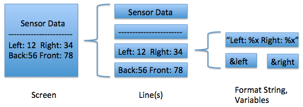
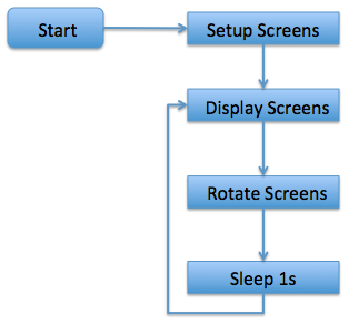
The IO task utilizes the LCD API to display LCD "screens". A screen is a custom-defined object containing "line" objects. Lines consist of a format sting (in the printf format) and optional variables. All screens are stored in a vector, of which the front object is always displayed on the LCD. To change the screen, the vector is simply rotated left or right (forward or backward). For simplicity, the screens are rotated every second. However the screens can be rotated by button press, timer, external interrupt or even CAN message.
The data objects that are stored in shared memory by the RX task make up the variables in the format strings described above. To accomplish this, the data types for these variables are char**, or a pointer to a char pointer. That way, we can just supply the memory location of the char* that is constantly being updated by the RX task. This simplifies the implementation of the IO Task and ensures the latest data is used when printing the screens.
Communication (Bluetooth & Android) controller
Self-driving car Android App
The purpose of the android app is to allow the user to connect with the self-driving car, view the current location of the car on Google Map, set the destination on Google Map, start driving, and stop driving.
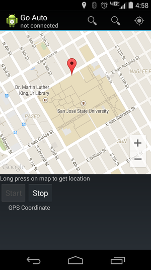
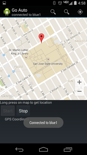
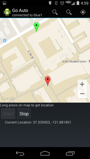
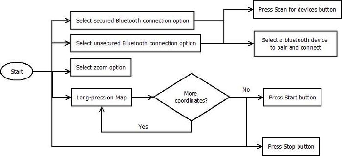
The UI is very simple and easy to use. The first activity at launch contains a google map, start button, stop button, and a few options on the action bar. There are two options (secured bluetooth and unsecured bluetooth) for selecting a bluetooth device. The last option zooms the map to a default location, San Jose State University. The second activity is started when selecting the secured or unsecured option in the action bar of the first activity. The second activity enables the user to scan bluetooth devices and select a device to pair and connect. Once connected to the bluetooth device from the car, the current location of the car is marked on the map. The user can create multiple markers on the map that represent where the car should go. After the user is ready to begin driving the car, the user can press the start button.
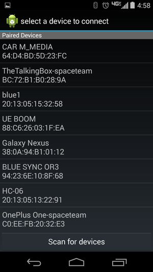
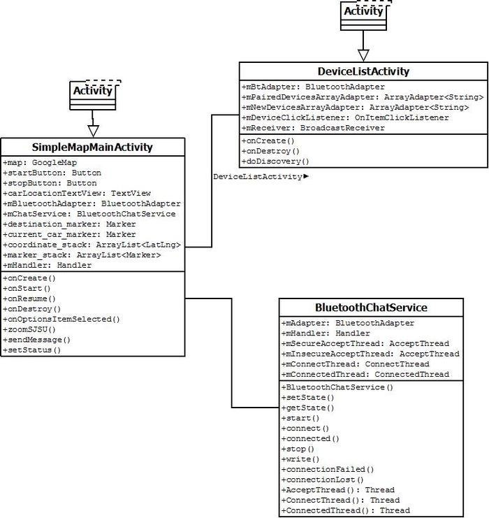
There are three main classes used in the android app for self-driving car: SimpleMapMainActivity, DeviceListActivity, and BluetoothChatService. SimpleMapMainActivity is the main activity that contains Google Map, start button, stop button, bluetooth options, and map zoom option. Most of the UI elements are initialized in onCreate and onStart methods, as well as in the activity_map.xml in the res folder. In beginning of the app, the bluetooth adapter is initialized when bluetooth is available on the android device and is enabled. If it isn’t enabled, there will be a dialog which will request the user to enable bluetooth. With the bluetooth adapter, bluetooth communication may begin. Also in the beginning of the app, the bluetooth chat service is created and it is provided with the handler of the main activity. The bluetooth chat service will be operate in the background, independent of the main activity. Every time the service receives data from bluetooth, the service will provide that data on the main activity’s handler. In SimpleMapMainActivity, options are created with onOptionsItemSelected and onCreateOptionsMenu. Two of the three options will launch the DeviceListActivity activity. This activity will allow the user to scan and select a bluetooth device. Before selecting a bluetooth device, the user should scan available bluetooth devices by pressing “Scan for devices”. Once this button is selected, bluetooth adapter is put in discovery mode. After it discovery is finished, the user must select the bluetooth device associated with the self-driving car. In our case, the device is blue1. Once the bluetooth device is selected, the bluetooth address is sent back to SimpleMapMainActivity, where it can connect the bluetooth adapter to the specific bluetooth device.
Communication Controller on Self-driving car
The communication controller interacts mostly with the geographical controller. This controller takes care of broadcasting the START and STOP commands, as well as the destination GPS coordinates in longitude and latitude so the car can be started, stopped, or notified of the direction where it should head to. As described in the CAN communication table section, the communication controller will send the commands and destination data using unique message ids. Geographical controller will then grab the data for further processing. The communication controller interfaces to the bluetooth module (HC-06) through UART3 port of the SJSUOne Board. The bluetooth module acts as a transparent wire between the communication controller and the android device. In order to send and read value to the android device, we just need to send and receive data to and from the bluetooth module at a specific baudrate. The baudrate can be programmed when the device is not currently paired to a device. Our bluetooth module's baudrate is programmed to be 38400. This was done by sending an AT command, AT+BAUD6, to the module through serial communication.
Controller Communication Table
| Controller ID | Controller |
|---|---|
| 0x01 | Master Controller |
| 0x02 | Geographical Controller |
| 0x03 | Motor Controller |
| 0x04 | Sensor Controller |
| 0x05 | IO Controller |
| 0x06 | Communication (Bluetooth Bridge/Android App) Controller |
| Sl. No | Message Number | Purpose | Data layout |
|---|---|---|---|
| 1 | 0x501 | Send Throttle and steering to motor | throttle
steering |
| 2 | 0x502 | Start car | |
| 3 | 0x503 | Stop car | |
| 4 | 0x101 | Broadcast request revision | |
| 5 | 0x102 | Broadcast Set time | |
| 6 | 0x103 | Request TX count (broadcast) | |
| 7 | 0x104 | Request RX count (broadcast) | |
| 8 | 0x105 | Send TX count (LCD) | |
| 9 | 0x106 | Send RX count (LCD) | |
| 10 | 0x107 | All controllers initialize |
| Sl. No | Message Number | Purpose | Data layout |
|---|---|---|---|
| 1 | 0x301 | Broadcast Start command | |
| 2 | 0x302 | Broadcast Stop command | |
| 3 | 0x303 | Broadcast GPS destination set by Android | byte [0-3] : (float), Longitude
byte [4-7] : (float), Latitude |
| Sl. No | Message Number | Purpose | Data layout |
|---|---|---|---|
| 1 | 0x501 | Broadcast front sensors values | byte[0]: Right ultrasonic sensor value in inches
byte[1]: Front ultrasonic sensor value in inches byte[2]: Left ultrasonic sensor value in inches byte[3]: Front bottom infrared sensor value in inches |
| 2 | 0x502 | Broadcast back infrared sensor value | byte[0]: Back infrared sensor value in inches |
| 3 | 0x503 | Broadcast battery sensor value | byte[0]: current/voltage sensor value in percentage |
| 4 | 0x504 | Broadcast light sensor value | byte[0]: light sensor value as integer |
| 5 | 0x505 | Broadcast tilt sensor value | byte[0]: X-Axis tilt sensor value as integer
byte[1]: Y-Axis tilt sensor value as integer byte[2]: Z-Axis tilt sensor value as integer |
| Sl. No | Send Code | Description | Data |
|---|---|---|---|
| 1 | 0x501 | RPM and Speed data broadcast | RPM (4 bytes) Speed (4 bytes) |
| 2 | 0x301 | Start | Receive only |
| 3 | 0x302 | Stop | Receive only |
| 4 | 0x501 | Byte[1] - forward/reverse; Byte[2] - Steer left/right; | Receive only |
| Sl. No | Message Number | Purpose | Destination |
|---|---|---|---|
| 1 | 0x301 | Start command for car | Central Controller |
| 2 | 0x302 | Stop command for car | Central Controller |
| 3 | 0x303 | Go to a predefined Destination. | Central Controller |
Testing & Technical Challenges
Sensors
The first challenge was the positioning and spacing between the sensors. The sensors were mounted on a 3D printed bracket for initial testing but the angle between the brackets seemed to cause interference and was not giving optimum values. The sensors were then individually mounted further apart to reduce interference. The detection distance was tweaked by trial and error and finally settled on the value of 36 inches for the front, left and right sensors and 7 inches for the back sensor.
The second challenge was dealing with erroneous values. Using ADC to interface sensors lead to certain erroneous values that didn't have the desired effect and after some testing, the sensor interface was changed to pulse width. This lead to more robust values after filtering.
Another challenge was the initial skewed alignment. It was difficult to detect whether the direction of the running car was changing because of the motor response to sensor values or the alignment of the tires. The group eventually decided to get a new car that rectified the alignment issue.
Sensors Configuration and Implementation
We used LV-MaxSonar series MB1010 high performance ultrasonic sensors for our application. The sensors detects objects from 6 inch to 254 inches and can be interfaced to ADC or pulse width output. We found the ADC values were inconsistent and due to the constraint of number of ADC pins on SJONE board , we used PWM to configure the sensors. We mounted three sensors in front of the car and we found the values were not consistent as it was reflected from the ground, hence we elevated the sensor placement. The sensor configuration is explained
Motor Controller
Issue 1
As we were using Electric Speed Control (ESC) to control the speed of motor we faced issues based on inconsistency of the speed. This could have been solved easily if we used H-bridge chip. When ESC was supplied with particular PWM signal it would work at desirable speed but when turning off the ESC and turning on the ESC the speed would change for the same PWM signal supplied. This inconsistency of the speed can easily damaged the motor as it was hard to predict when the motor will switch from forward to backward motion. So to fix this issue we had to connect the ESC to oscilloscope and turn on the transmitter. As soon as the transmitter is turned on the transmitter send a fix signal to ESC for some time that could have been in milli seconds. By doing this the ESC get initialized and once the ESC has initialized the transmitter can send a signal to go forward or reverse.
So we wrote a code to initialize the ESC. Before we sends the signal to ESC to move forward or reverse we send a fix PWM signal to ESC for one second to initialize ESC and this signal was sent from the main function.
Issue 2
The servo that came with the RC car wasn't fast enough to respond to left and right movement of the car. Car would hit the obstacle and than the wheel would rotate in opposite direction. So we change the servo with faster response time.
System Testing
| Sl. No | Test Case | Test Description | Result |
|---|---|---|---|
| 1 | Initial CAN communication of all controllers | Check if all the controllers are broadcasting the periodic message on CAN bus and receiving the data | All controllers PASSED |
| 2 | Obstacle avoidance | Obstacle by integrating the ultrasonic sensor | Obstacle avoidance PASSED |
| 3 | LCD display | Displying all the values including CPU Utilization, CAN message count, and message from the controllers | LCD display of all message PASSED |
| 4 | Building Android application | Check if the Android application sends the destination by Bluetooth | Communication PASSED |
| 5 | Point to Point movement | Test Car runs by setting two way points | Point to point car movement PASSED |
| 6 | Checking if Car runs with multiple way points | Check if the car works with multiple way points | Multiple way points steering PASSED |
Future Enhancement
Sensors
It would be ideal to add another infrared sensor to the front lower portion of the car for cliff detection. It would also be good to have a bigger 3D printed bracket to mount the sensors that match our measurements requirements. This would add to the visual appeal and also reduce tangling mess due to the wires.
Motors
Enhance central and motor controller code to dynamically increase/decreased speed
Conclusion
A self-driving car was successfully designed implemented and tested. We changed the design multiple times during the course of the project. While the final product is not perfect, autonomous navigation of the car has been achieved. If we had more time we would have improved the car navigation and added more features. Given a single destination, or a list of way-points, the car can successfully navigate to the final destination avoiding all obstacles in its path, albeit a little slowly.
This project was a great learning experience since it covered all aspects of a product design: mechanical design and assembly, procurement of parts, software design, coding and testing, and team work.
Project Video
Demo : http://youtu.be/a9ceLDJN67M
Teampics : http://youtu.be/TJW7AsHpXfE
Project Source Code
References
Acknowledgement
References Used
- Preetpal Kang, Lecture notes of CMPE 243, Computer Engineering, Charles W. Davidson College of Engineering, San Jose State University, Aug-Dec 2014.
- en.wikipedia.org/
- MaxBotix 2012, http://www.maxbotix.com/articles/031.htm
