F13: Obstacle Avoidance Robot
Contents
Object Sensing and Avoidance Robot
Abstract
The purpose of this project is to develop a robotic platform using the class issued NXP LPC1758 development boards. The main operation of the robot will be to sense objects near it using a distance sensor and then use a moveable platform to steer away from the sensed objects.
Objectives & Introduction
Team Members & Responsibilities
- Joel
- Sensor Development
- Dan
- Motor Drive Development
Schedule
| Week# | Date | Task (Planned) | Task (Result) |
|---|---|---|---|
| 1 | 10/8 | Project Proposal | Complete |
| 2 | 10/15 | Research parts | Complete |
| 3 | 10/22 | Order & receive parts | Complete. Received parts 10/23. Found that another order was necessary. Only one motor, needed two. Need bracket hardware. |
| 4 | 10/29 | Research motor driver & A/D converter functions | Complete. Not as many A/D channels as hoped for I/R sensor. Considered external A/D, decided on reducing A/D inputs to match available channels. |
| 5 | 11/5 | Write & test motor driver & A/D code | Complete. One motor drive output seems a little weaker than the other. Viewed outputs on oscilloscope, no issue found. |
| 6 | 11/12 | Write & test combined avoidance robot code | Complete. Updated motor driver. Able to achieve autonomous motion. See video. |
| 7 | 11/19 | Write & test combined avoidance robot code. | Complete. Calibrated I/R sensor. Integrated all functionality together. See video. |
| 8 | 11/26 | Work documentation | Worked algorithm and schematic documentation. Took videos for final presentation. |
| 9 | 12/3 | Project due | Complete. Presentation shown during class. |
Parts List & Cost
| Item | Description | Qty | Unit Cost | Total Cost |
|---|---|---|---|---|
| 1 | #713 TB6612FNG Dual Motor Driver Carrier | 1 | $5.00 | $5.00 |
| 2 | #2107 Pololu 5V, 600mA Step-Down Voltage Regulator D24V6F5 | 1 | $5.95 | $5.95 |
| 3 | #965 0.100" (2.54 mm) Breakaway Male Header: 1x40-Pin, Straight | 4 | $0.99 | $3.96 |
| 4 | #1134 Pololu Carrier with Sharp GP2Y0D810Z0F Digital Distance Sensor 10cm | 4 | $6.95 | $27.80 |
| 5 | #1700 Premium Jumper Wire 50-Piece Rainbow Assortment F-F 6" | 1 | $12.49 | $12.49 |
| 6 | #1944 Aluminum Standoff: 1" Length, 2-56 Thread, M-F (4-Pack) | 2 | $1.59 | $3.18 |
| 7 | #1940 Aluminum Standoff: 1/4" Length, 2-56 Thread, M-F (4-Pack) | 2 | $1.29 | $2.58 |
| 8 | #1067 Machine Hex Nut: #2-56 (25-pack) | 1 | $0.99 | $0.99 |
| 9 | #1955 Machine Screw: #2-56, 1/4" Length, Phillips (25-pack) | 1 | $0.59 | $0.59 |
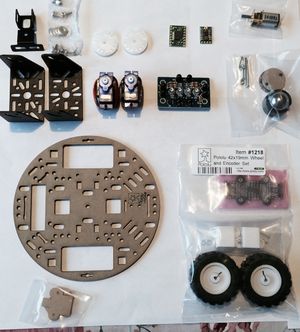
| 10 | #1501 Pololu 5" Robot Chassis RRC04A Solid Black | 1 | $7.95 | $7.95 |
| 11 | #1218 Pololu 42x19mm Wheel and Encoder Set | 1 | $39.95 | $39.95 |
| 12 | #2365 50:1 Micro Metal Gearmotor MP | 2 | $16.00 | $32.00 |
| 13 | #925 T Connector Male-Female Pair | 1 | $1.49 | $1.49 |
| 14 | #955 Pololu Ball Caster with 3/4" Metal Ball | 1 | $2.99 | $2.99 |
| 15 | 2150441 SENSOR, IR COMPOUND EYE, 200mm | 1 | $9.95 | $9.95 |
| 16 | 2157870 PAN/TILT, 2-SERVO INCL, 8g | 1 | $14.95 | $14.95 |
| 17 | LiPo Battery | 1 | $7.00 | $7.00 |
| 18 | SJSU Development Board | 1 | $75.00 | $75.00 |
| Total | $253.82 |
Design & Implementation
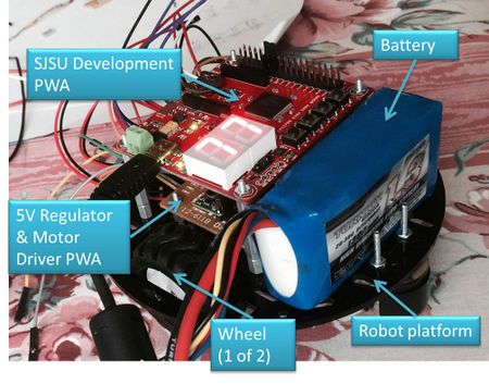
The photo below shows the implementation/progress as of 11/10/2013.
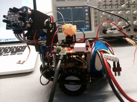
The photo below shows the implementation/progress as of 11/17/2013. The oscilloscope in the background was being used to display the PWM signal for the motor drives.
Hardware Design
The design is built onto a Pololu 5" round robotic chassis that is designed to accept two independently driven wheels. As Figure 1 shows, there are two electronic boards stacked onto each other. The board on top is the SJSU NXP LPC1758 development board. Below that is a board that contains the motor driver and the 12V to 5V regulator. This board also worked well for a power distribution board so several headers are located on this board.
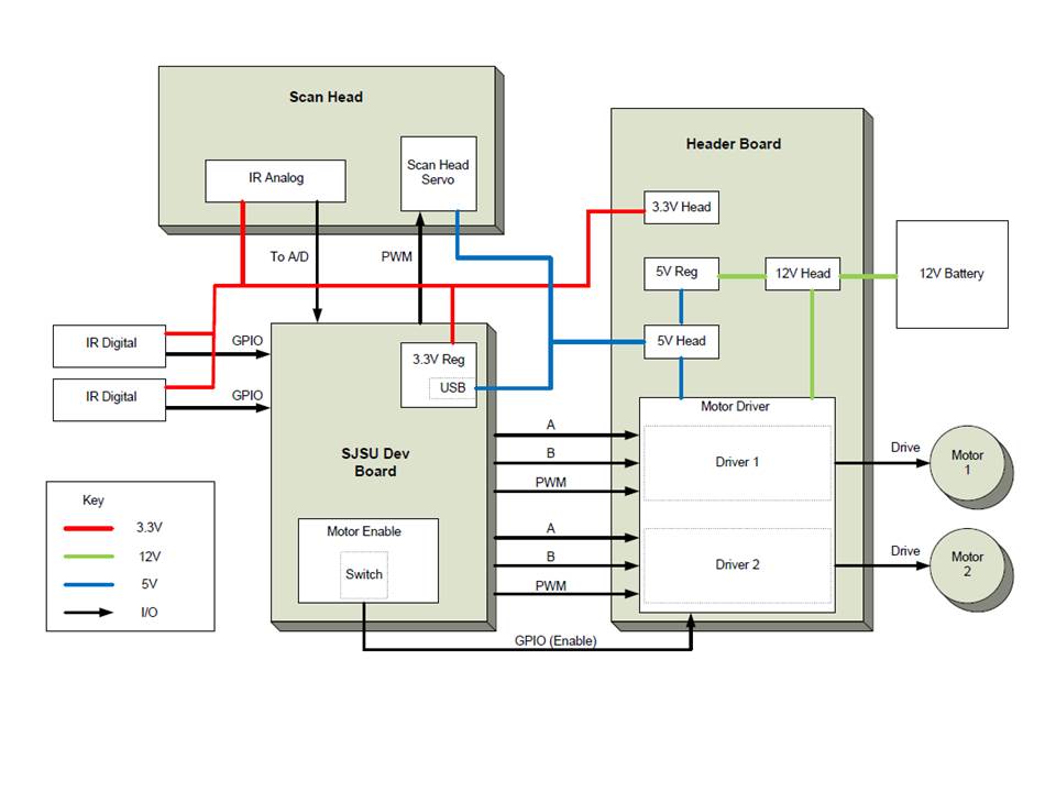
The design has three main voltages. The battery pack provides 12V to run the motors and as input power to the 5V switching regulator. The 5V out from the switching regulator provides power for the SJSU board at the USB interface as well as for the motor driver logic and ultimately the I/R sensor power. The 5V to 3.3V linear regulator on the SJSU development board was utilized to regulate the 5V input to 3.3V. The 3.3V was then sent off the SJSU board to power the analog and digital I/R sensors. The high level schematic in Figure 4 below shows these details.
Hardware Interface
The design uses the SJSU board PWM and GPIO outputs to drive the scan head servo motors and wheel motors. The GPIO are also utilized for the inputs from the digital sensors. An A/D input into the board reads voltage from the analog I/R sensor.
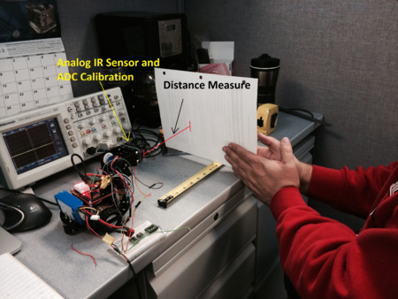
In order to integrate the I/R sensor with the robot, we need to perform a calibration to determine the characteristics of the sensor. The basic calibration procedure was to read the A/D counts as a white surface was held at a particular distance from the sensor head. A snapshot of this procedure is shown below in Figure 5.
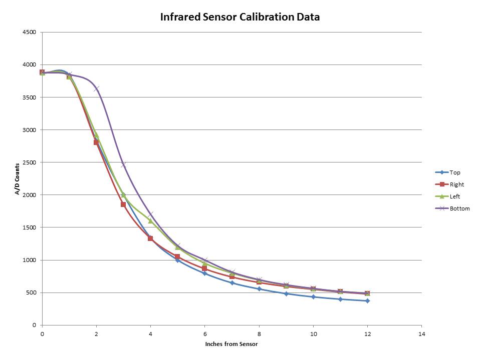
The chart below shows the calibration data from each of the four sensors on the I/R sensor head.
From this data, we were able to determine that a sensor reading less than 1000 counts meant that an object was far enough away to take no action. However a reading of greater than 1000 counts meant that an object is getting closer than 5 to 6 inches and it is time to stop the robot from going forward and run an algorithm to determine the best direction to move the robot.
Software Design
We have working functions that can drive the motors forwards and backwards and turn the robot left and right. Other functions read the A/D input from the analog I/R sensor. The status of the digital I/R connected to the GPIO are also read. The main functionality of the algorithm is to drive forward until an object is sensed. If one of the digital I/R sensors sensed the object, then the robot backs up for more clearance. The scan head is then used to find the clearest path and the wheels turn the robot in that direction and begin moving forward again.
The code also contains a few housekeeping functions. For instance, one of the switches is used to enable/disable the motors. Also, the light sensor is used to adjust the analog I/R sensor threshold.
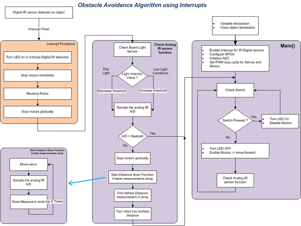
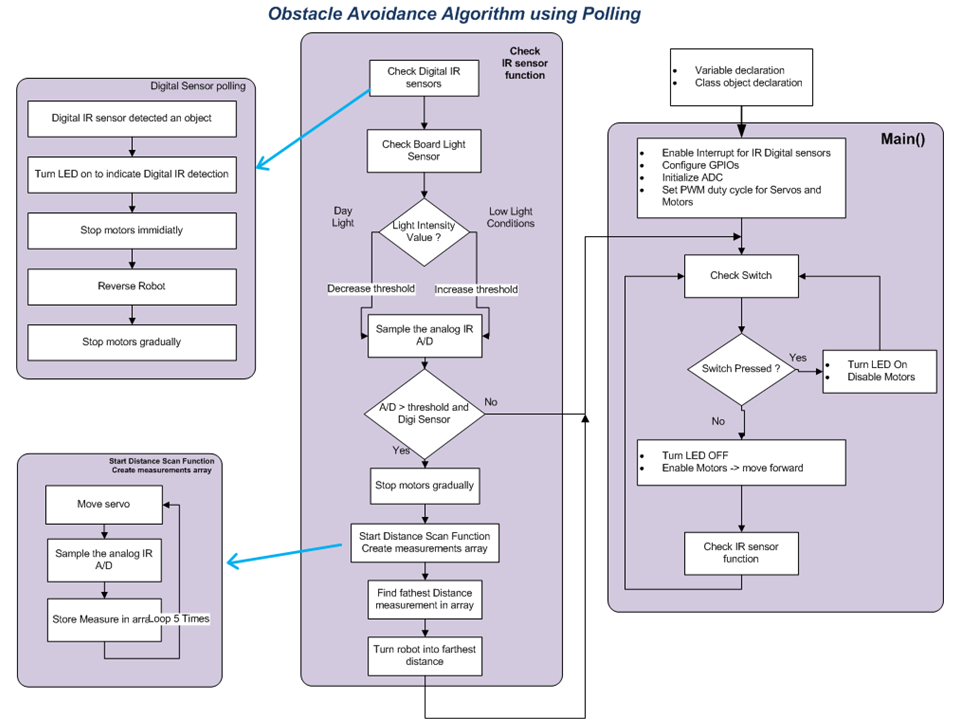
Two different implementations of the algorithm were tried. One with interrupts and one without interrupts (polling). Without some sort of masking functionality, interrupts do not work well. This is discussed further in the "Issues" section.
Below are brief descriptions of each of the software functions.
Main Function
The main function declares all the variables and initializing functions. It scans the switch (sw1) on the board, to enable the robot. When a button press is detected, the main obstacle avoidance function is called.
check_ir_sensor_function
This function is the main algorithm for this robot. The function works by first adjusting the threshold of the analog Infra-Red sensor as function of the external light.
It will then scan the digital IR sensors and the analog IR sensor. If an object was detected on the digital sensor, the robot will reverse a few inches and call the “distance_scan_function”.
If an object was detected on the analog sensor and the reading is below the set threshold, it will call the “distance_scan_function”.
When computing the “distance_scan_function”, the results of the scan are sent to the motors object to turn the robot into the clearest path. Once pointed to the clearest path, it will then continue strait.
distance_scan_function
This function is the “head scanning” function. It scans 5 angles of view in front of the robot, reading the A/D on each angle and storing the read into an array. When all 5 measurements are complete, it will find the farthest distance and store into the return value.
When using the interrupt version, everything remains the same, except the digital sensors are not being polled, rather firing an interrupt when detecting an object. The interrupts need to be enabled in the main function. The interrupts will then call the ir_irq function.
ir_irq
This function will turn on an LED to indicate the interrupt. The function will then stop the motors immediately, reverse the robot a few inches and will then call the "distance_scan_function".
Algorithm with Interrupts
File:Obstacle SoftwareDiagram.pdf
Algorithm without Interrupts (Polling)
File:Obstacle SoftwareDiagram polling.pdf
Implementation
Infrared (I/R) Sensors
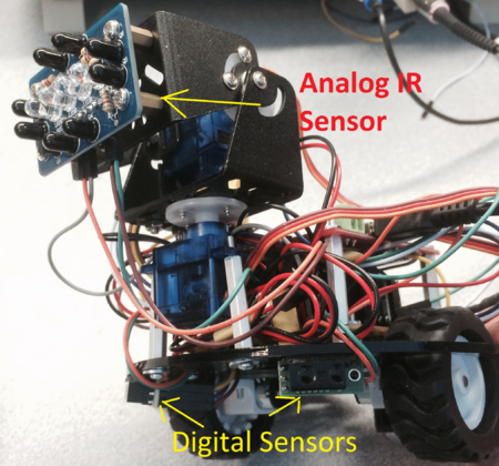
Two types of I/R sensors were used. The first was an analog sensor shown in Figure 9 below. The analog sensor can gauge the approximate distances to objects based on the calibration found above. The sensor sits on the scanning head of the robot and is used to find the clearest path for the robot to go next.
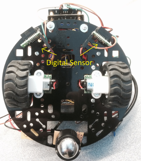
Figure 10 below shows the detailed location of the digital sensors. These sensors change state when an object is approximately 2 - 10cm in front of them. The main purpose of the digital sensors is to provide more coverage area for sensing objects. While the robot is moving forward, the digital sensors are used to find objects lower and to the side compared to what the main scanning head can see.
Wheels and Motors
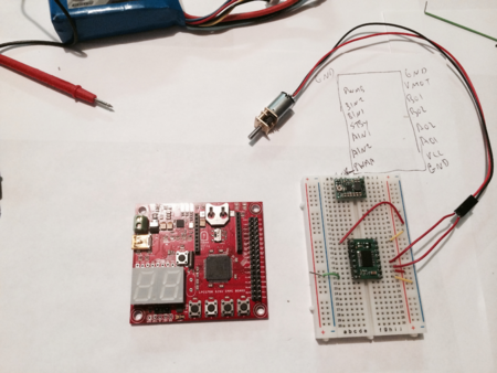
Two independently controlled wheels were used. A motor controller was considered in the beginning, but ultimately a motor driver was utilized instead. A motor controller usually contains all of the functions to drive the motors and is typically commanded via I2C or similar communication bus. A motor driver, on the other hand, basically amplifies a PWM signal that is sent to it and will also contain direction controls. For this robot, a motor driver was used since the NXP microcontroller already contained PWM and motor controller functionality. It was thought that this solution would provide the most versatility. Figure 11 below shows the motor and motor driver being tested on a bread board before being implemented onto the robot platform.
As mentioned above, the PWM functionality of the microcontroller was used to run the motors through the motor drivers. In software, different functions were created for going forward, backwards, turning right and turning left. The different functions are needed to set the "A" and "B" GPIO correctly as these lines control whether and individual motor will turn forward or backward. For example to make a right hand turn, the left wheel should move forward while right wheel turns backwards.
Testing & Technical Challenges
Issue #1
Voltages: We had an issue with what voltages to use to drive everything. At first, we thought we might need 12V for the motors, 3.3V for the SJSU board, and 5V for the motor control logic. We also ran into the bug on the SJSU board when it is powered directly with 3.3V. When this is the case, the USB to RS232 chip holds the board in reset.
Solution: In the end, we found that the GPIO pins were 5V tolerant and therefore could accept 5V from the motor control driver. We also found that the best solution to power the SJSU board was with 5V through the USB power to keep the USB to RS232 chip from resetting the NXP chip.
Issue #2
PWMs: We discovered another limitation in with this board. It appears only one frequency of PWM can be used at a time. The servo of the scan head must be run at 50Hz, while through experimentation, it was found that the wheel motors run the best at 400Hz.
Solution: After looking at several options, the simplest solution was to run both of the motors at 50Hz. The wheel motors are not as smooth and seem to make more noise at this frequency, but they still run fine. The spec sheet of the motor was reviewed and it appears that this frequency is acceptable.
Issue #3
Interrupts: Code was written to try and utilize the interrupt capability of the board. During testing of this code, we found that if several interrupts came in at once, the code would not behave as expected
Solution: The short term solution was to use code that polls the sensors instead of waiting for interrupts. However we believe a better long term solution would be to use masking in conjunction with the interrupt. The digital I/R sensors would be masked to disable further interrupts until the robot had gone through a direction change routine.
Conclusion
The Obstacle Avoidance Robot utilized nearly as many hardware skills as it did software skills. There were many challenges in trying to connect the various pieces of hardware with all of their unique requirement ranges. Everything from different voltage requirements to varying frequency requirements. There were also software limitations to overcome as well. For instance, it would have been nice to be able to have two different PWM frequencies at the same time: one for the motors and another for the servos. However we found that we were able to make enough compromises to get the hardware and software to work well enough together without needlessly overcomplicating the design.
Project Videos
The video below shows the first autonomous testing of the motor functionality.
This video shows the complete functionality of the robot. However more calibration of the motors was required
The two videos below show the full capability of the final design. These videos show the performance of the robot on different surfaces and with different obstacles.
