F12: Unified Wireless Health Monitoring System
Contents
Unified Wireless Health Monitoring System
Abstract
Our project will take in sensor data (pulse sensor + temperature sensor) through the LPC2148 submit it to an online database. The purpose of the project is to simplify health monitoring for patients while allowing them some mobility. Both the patient and their doctor will be able to see the patient's progress via a WEB GUI.
Objectives & Introduction
Objectives
- Create a mobile device that attaches to a user in order to retrieve health data from the user.
- Use 2 health monitoring sensors to retrieve 2 different types of data.
- Submit the sensor data wirelessly to an online database via Xbee & HTTP protocol.
- Give verified users and their doctors access to their health data on the online database.
- Display the health data from the online database to a WEB GUI, using charts to monitor progress.
Team Members
- Gurpreet Singh
- Michelle Chen
- Hai Do
Roles & Responsibilities
| Task | Responsibility |
|---|---|
| Xbee Wireless Configuration |
Gurpreet |
| Xbee UART driver for LPC2148 |
Gurpreet |
| PulseSensor A2D driver for LPC2148 |
Michelle |
| TMP102 I2C driver for LPC2148 |
Michelle |
| UART to SQL data conversion on PC-End |
Hai |
| Online Database Configuration |
Hai |
| Web GUI Configuration |
Hai |
Schedule
| Week Number | Scheduled Items | Actual |
|---|---|---|
| 1 |
|
|
| 2 |
|
|
| 3 |
|
|
| 4 |
|
|
| 5 |
|
|
| 6 |
|
|
Parts List & Cost
| Part | Quantity | Cost |
|---|---|---|
| Xbee Series 2 Module | $50 | |
| LPC2148 CPU + MP3 Development Board | $60 | |
| Plastic Enclosure + Accessories | $25 | |
| Xbee USB Adapter | $25 | |
| Pulse Sensor | $28 | |
| I2C Digital Temperature Sensor | $3 |
Design & Implementation
Hardware Design
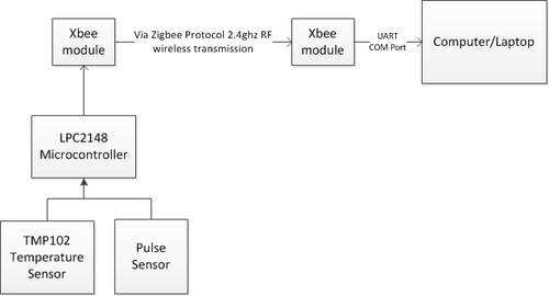
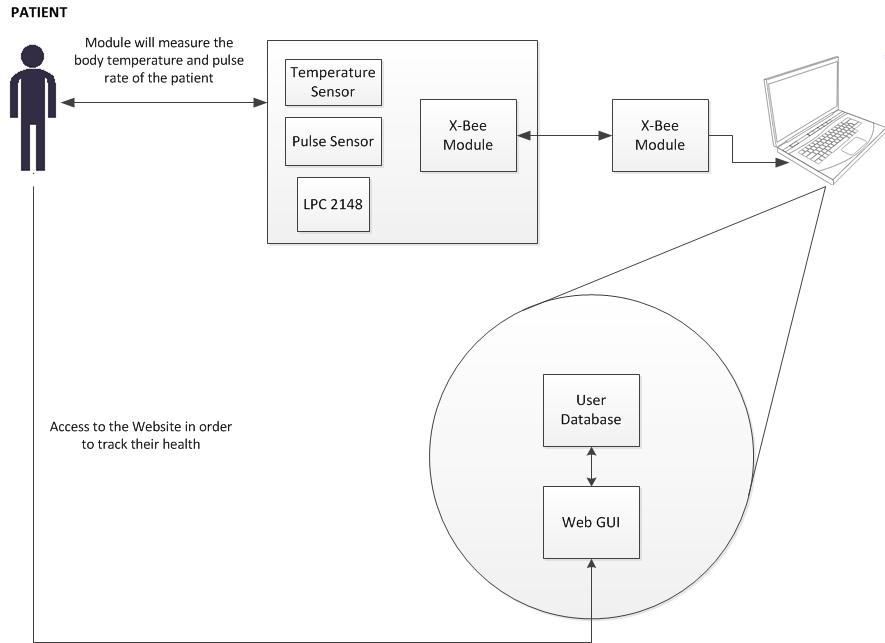
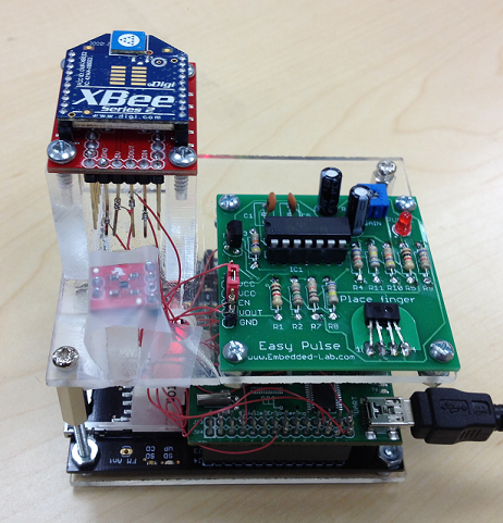
The entire hardware block diagram can be seen below in figure 1. The architecture was setup so that the hardware would be encompassed in 2 different sections. The first section would be a physical enclosure that houses the LPC2148 micro-controller, the temperature sensors, the pulse sensor, and a series 2 Xbee module. The second section of the setup would include another Xbee module along with a computer/laptop. The reason the hardware is divided in 2 sections is due to the 2 sensors, Xbee module, and the micro-controller being in an enclosure that the patient would use. The Xbee module would then wirelessly transmit the UART data via the Zibee Protocol to the next Xbee which is connected to a computer. The computer would then open the COM port of the Xbee module and parse in the incoming UART data for submitting to the online database via mySQL.
All the individual hardware components utilize 3.3v of Vcc, and are connected to a shared GND. The wireless enclosure is connected via USB to a computer, which powers all the individual hardware components.
Hardware Interface
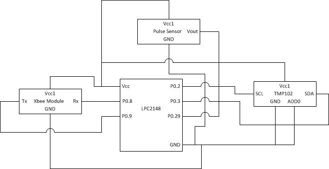
Below in figures 2 and 3, the TMP102 temperature sensor Pins and system level connections can be seen. In order to implement the full hardware setup of the enclosed wireless module, the individual pins were connected as shown in Figure 2.
The I2C0 bus was used for the TMP102 temperature sensor, along with UART0 for terminal communication with the micro-controller, and UART1 for Xbee communication with the micro-controller. CAP0.0 was used as the digital input capture signal for the Pulse Sensor, in order to use timers to calculate the beats per minute of the patient.
The Xbee module has 2 primary modes of operation, API and transparent. In API mode, the ADC and other internal perks of the Xbee can be utilized. For our purposes, we only needed to utilize the Xbee to transmit wireless UART data, and thus transparent mode works as a functional requirement. For transparent mode, only 4 pin connections are necessary as it can be seen in figure 2. The Vcc and GND pins are connected to power and ground, while the Tx and Rx pins are connected to the micro-controllers Tx and Rx UART1 P0.8 and P0.9 pins. This basically allows both Xbee modules to communicate wireless UART data via the Zibee Protocol while both of the Xbees have been properly configured to the same PAN ID, and each other's 64-bit low/high address.
The Pulse sensor used is an embedded kit from Embedded Lab, which utilizes the TCRT1000 photoplethysmography sensor. It only requires 3 pins, which are Vcc and GND for power and ground; and the last being Vout. The Vout is used as a digital input to our micro-controller via a GPIO input to P0.29.
The TMP102 is a digital I2C temperature sensor. It has 6 pins, but only 5 are used for our purposes. As it can be seen in figure 2, the alert pin is not connected because the ALERT mode on the sensor is not used. Add0 is connected to GND as well, while the SCL and SDK are connected to the micro-controller's I2C0 bus pins of P0.2 and P0.3.
The TMP102 temperature sensor utilizes the I2C protocol as stated above, but it requires us to read a 3 byte frame in order to completely receive the temperature value including the 3 point decimal precision. It can be seen below that the table for the TMP102 shows which bits are required for which data values. The last byte is used to indicate the decimal precision value, the middle byte and the last byte is used for the actual temperature.
The psuedo-code used to read the 3 byte frame from the TMP102 and also calculate the actual temperature is shown below.
float tempTask()
{
	initialize_I2C0(300000);
	unsigned char datavalue1='S';
	unsigned char datavalue2;
	unsigned char datavalue3;
	float temp,num;

        //Write Slave Address with W-bit 0x90
        //Now pointing to register 0x00 to read from TMP102
        //read the 3 data bytes from the TMP102
        //shift the last byte to read in correct temp
	datavalue3=(datavalue3>>4);
	num=(float)datavalue3;
	num=0.0625*num;
	temp=(float)datavalue2+num;
	float temperature= (temp*1.8)+32;

	return temperature;
}
Timers were used to calculate the beats per minute from the pulse sensor for P0.29's CAP0.3 digital input. The timer registers used were T1TC, T1PR, T1PC, and T1TCR. Since the timers needed to be continuously running while the UART0 user interface task was running, a task was allocated for the Pulse Sensor, and a queue was used to send the BPM value to the userinterface task.
The following psuedo-code is used to calculate heart rate (beats per minute) for the Pulse Sensor:
void pulseTask(void * pvParameters)
{
   setupOSHANDLES();
   declare variables;
   initialize timers;

    //loop that runs always in background
    for(;;)
    {
	results = adcRead();
	if(results>= pulse peak value && count==0)
	{
	   //Reset timer
	   //START COUNTING
	   count=1;
	}

	if(results = next pulse peak && count==1)
	{
	count=2;
	}

	if(results = 3rd pulse peak && count==2)
	{
	//STOP COUNTING
	count=0;
	time=0.001*(float)T1TC;
	BPM=60/time;
	}

        //time out loop to detect when to reset bpm
        if(T1TC>3000)
	{
	BPM=0;
	}
        //finally send queue of BPM for the userinterface
	xQueueSend(osHandles->queue.heart_rate,&BPM, 1);

	}
}
Software Design
- LPC2148 FreeRTOS
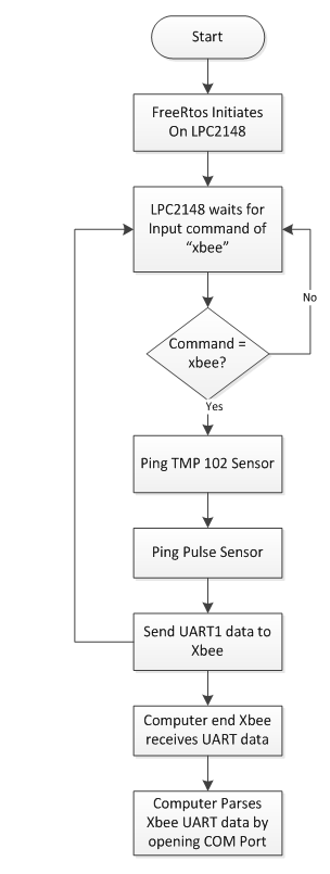
- FreeRTOS was used as the OS for our LPC2148 micro-controller. Tasks were allocated for the userinterface (UART0) and the pulse sensor in order for both of them to work in the background. All the primary function calls were done in the userinterface once the command "xbee" had been input into the terminal. Once the command had been received, the following would take place:
 1. Initilaize all the variables.
 2. Poll the temperature sensor.
 3. Read in queue value of the BPM.
 4. Send the UART data over to the Xbee module via UART1 protocol.
 5. Delay for 100 ms in order to ensure the entire data segment was sent over to Xbee.
 6. Restart the userinterface loop.
To learn more about the FreeRTOS and how it allocates memory, visit the FreeRTOS Tutorial.
- MySQL Database
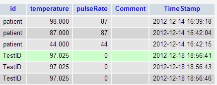
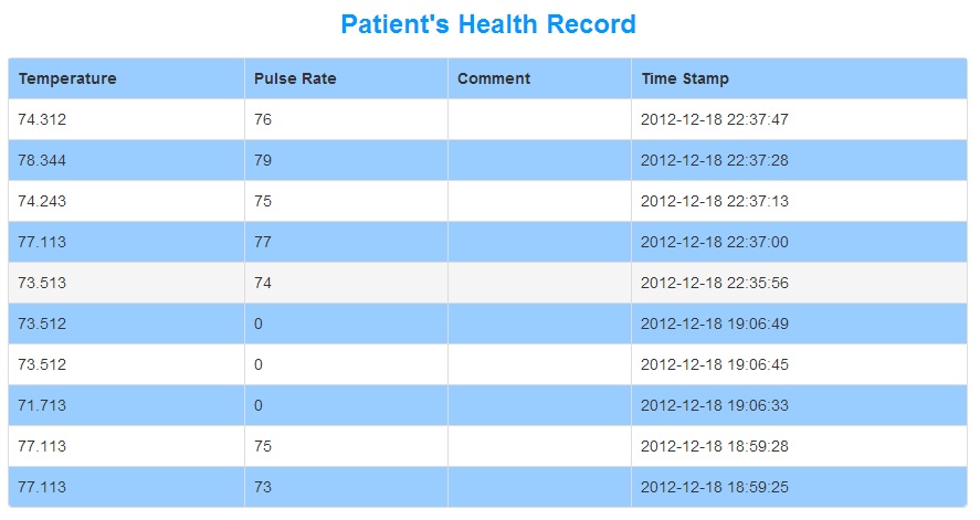
- The database will be used to collect and record data from both our temperature and pulse sensor. A database called "user" and a table called "patient" was created using phpMyAdmin. The patient table comprises of id, temperature, pulse, comments, and time stamp. Every time a string of data is received,it gets parsed and updated into their respective columns in the table. This table is shown below:
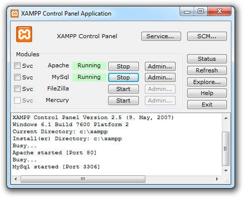
- In order to set up MySQL Database, XAMPP, an open source package which includes Appache HTTP Server, MySQL database, PHP, and Perl, will be used. With XAMPP installed, we are able to create a localhost PHP website that pulls data from our database.
- The following settings must be set to utilize XAMPP:
- Web GUI
- The Web GUI is a bridge between the clients and the server. It translates the data from the database into a form where users can visually see their real time temperature and heart beat. The Web GUI is a monitoring system for the patient to see their body temperature and heart rate. Also, the monitoring system can be accessed anywhere with an internet connection so the patient doesn't have to be hooked up to machines. Other users can also view patient data such as their prescribing doctors. The doctors are able to leave feedback to their patients and monitor their health situation without physically being in the hospital to do so.
Implementation
- System Architecture
- Hardware Implementation
- The hardware implementation can be seen below in the figure which represents the flowchart on how the hardware behaves. As it can be seen, the hardware does not wait to see what happens when it sends over the UART1 data. It immediately goes back into the userinterface task waiting for another commend from the user. This is done so that the software portion of the system can take over the parsing and the hardware can continue polling if necessary.
- Web GUI
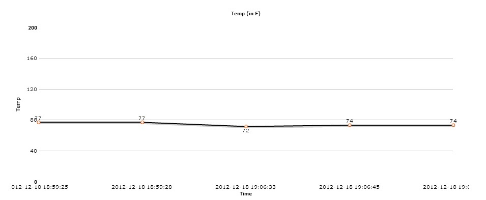
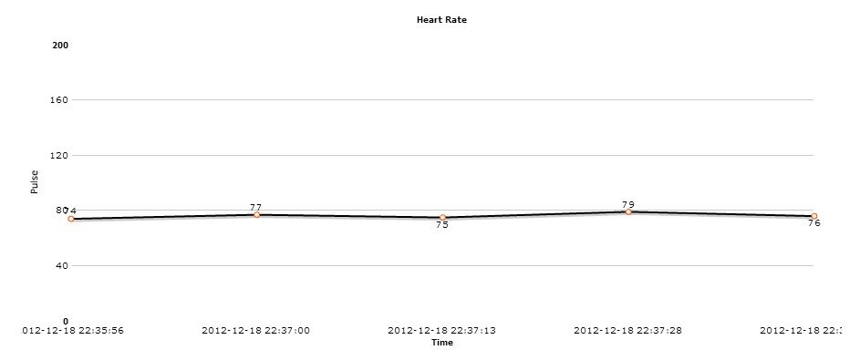
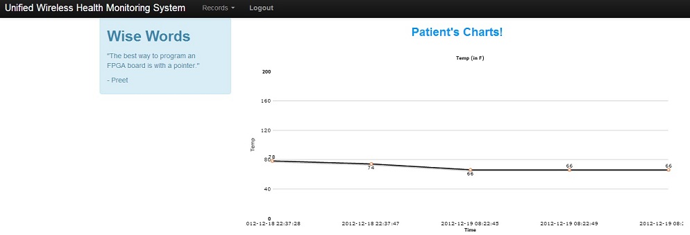
- The patients are able to access the website and check up on their temperatures and heart rates. Charts are also available to the patients along with the tables. The web GUI displays the data in real time. The values from both the table and charts are pulled from the MySQL database.
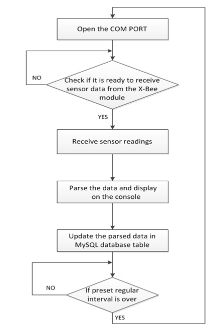
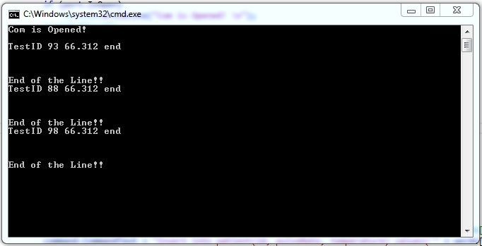
- To get the data, the comport has to be initialized to receive the incoming data from the xbee. If the comport is opened, then it is ready to receive incoming data. If it's closed, a message will display indicating that the comport it is unavailable to receive data. The data, in the form of a string, will be received and parsed using a split function and delimiters. The delimiters indicate separation between values so it can be inserted into the appropriate fields in the MySQL database. The parsed data will be displayed on the console as well as the charts on the web GUI. To be able to display the data, the charts and table are retrieving the data values from the database in real time. This is a continuous loop that will keep retrieving data until either the client or server side stops the process.
Testing & Technical Challenges
Testing
- To test our product, data was sent from the sensors over to the Xbee module connected to the computer. The computer then opens up the COM port of the Xbee module and then begins parsing data into the mySQL Xampp local database. Based off of the outputs displayed on the command prompt, we were able to determine whether or not any of our results were flawed. If so, we had adjusted the code to achieve our desired outputs.
Technical Challenges
- Pulse Sensor - Our first problem was that our pulse sensor wasn't able to successfully get accurate data and it was very sporadic. We had to replace the pulse sensor with a different one. Even then, the calibration was off and we had to manually change the gain of the sensor until it reached our desired range. Also, the sensor wasn't functioning properly on certain people.
- Temperature Sensor - We tested the temperature sensor through the console and it wasn't giving the right temperature. The parsed data from the temperature sensor wasn't sending the correct approximation over to the database.
- Parsing - In the beginning, we weren't able to parse decimal values because of our delimiters. We also didn't know what technique to use to split the data values being sent and how to update the database using the given strings.
- MySQL - We had trouble connecting to MySQL because of incorrectly identifying the user that held ownership to the specified database.
- Retrieving real time data using charts - The data was not retrieved correctly through the charts and table because the the web GUI was connecting to the wrong database.
If we were to restart this project from scratch, we would connect to only one database instead of many to make things simpler and easier to work around. For parsing, we might try using fewer delimiters.
Include sub-sections that list out a problem and solution, such as:
Conclusion
It was very fulfilling to work in a large scale project such as this since no one in our group had encountered such a long term project before. It has taught us a tremendous amount about ourselves and how we behave in a group over the course of the year. We have learned to work with each other as well learned a great amount of life lessons when encountering such a long-term project.
For the future, we hope to increase the scalability of the health monitoring system, as well as giving it the ability to go completely wireless on a possible 4G network, as well as different types of sensors used. Also, we would like to include a section where the doctors are able to sign in so they can view their patients online. The doctors will then be able to write comments about their patients in the comments section. The patients will then be able to read the comments left by the doctor(s) and will be able to get meaningful feedback. We would also like to create a registration form where new users/patients will be able to sign up. They are then able to monitor their health status online. The registration will work hand in hand with the log in system by updating and retrieve users' information so they can view their data via web GUI.
Project Video
The project video can be seen here at UWHMS.
Project Source Code
References
Acknowledgement
Thanks goes to the following persons for their contribution to the project:
- Preetpal Kang
- Sant Soy
- Shweta Nehra
- Ankita Gauri
References Used
- FreeRTOS Tutorial
- Web Development Tutorial
- Bootstrap Tutorial
- EasyPulse
- BitMasking Tutorial
- FusionCharts
