F12: OBD-II Android Monitor
Contents
OBD-II Android Monitor
Abstract
Interfacing a PLX Devices Kiwi Bluetooth to an Android mobile device. The PLX Devices Kiwi contains an ELM327 OBD-II to RS232 interpreter that gathers vehicle information. An Android application will be designed to gather real time information from the vehicle such as RPM, MPH, and intake temperature. The designed application will also be able to clear diagnostic trouble codes.
Features & Objectives
The OBD-II Android Monitor project establishes a wireless Bluetooth communication link between an Android mobile device and an automobile’s On-Board Diagnostics system (OBD). Information is transmitted between these components using an ELM Electronics ELM327 microcontroller. The ELM327 converts data from OBD-II protocols to RS-232, emulating the Bluetooth communication to run in serial port profile (SPP). To interface an Android device with the ELM327, an application will be designed. This application will have a graphical user interface (GUI) which will be able to display vehicle information such as MPH and RPM. The objectives for the OBD-II Android Monitor project is shown below.
- Establish communication with vehicle on board diagnostics computer with Android device
- Design and create Android Application with features of:
- a) Gather real time vehicle engine information such as Intake temperature, Engine coolant temperature, MPH, RPM, Voltage, etc.
- b) Clear check engine lights (CEL)
Team Members and Responsibilities
- Ryan James Cristobal
- Communication Link Between ELM327 and Android Application
- Parsing Data from ELM327 for Gauges
- Jonathan Luong
- Application GUI (Animated Gauges)
- Data Conversion
Schedule
| Week Number | Date | Planned Tasks | Actual |
|---|---|---|---|
| 1 |
10/20 - 10/26 |
|
|
| 2 |
10/27 - 11/2 |
|
|
| 3 |
11/3 - 11/9 |
|
|
| 4 |
11/10 - 11/16 |
|
|
| 5 |
11/17 - 11/23 |
|
|
| 6 |
11/24 - 11/30 |
|
|
| 7 |
12/1 - 12/7 |
|
|
| 8 |
12/8 - 12/14 |
|
|
| 9 |
12/15 - 12/19 |
|
|
Parts List & Cost
Hardware
- PLX Devices Kiwi Bluetooth [$99.95]
- ASUS Nexus 7 Tablet (running Android 4.2.1) [$249.95]
Software
- Windows Vista / 7 (32 or 64-bit)
- Eclipse IDE
- a) Must be 3.6.2 (Helios) or higher
- b) JDT Plugin (newer IDE packages will have this plugin included)
- Android SDK
- ADT Plugin (recommended but not required)
- a) 20.0.0 or higher
Design & Implementation
Hardware Design
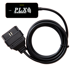
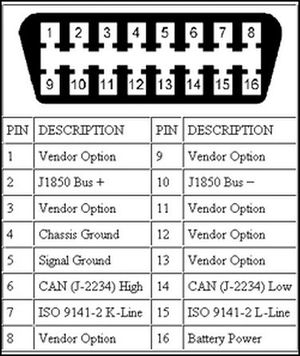
The OBD-II is a computer system built into modern vehicles. The OBD-II is responsible for monitoring and recording vehicle operating information such as temperatures and engine fault codes. Following different protocols such as SAE J1979, SAE J1850, ISO 9141-2, and etc, many users are using the OBD-II interface as a scan tool to diagnose the status of their vehicles. A pinout of the OBD-II connector is shown in Figure 2. There are many OBD-II adapter devices in the market that range from $25-$200. The OBD-II Android Monitor project uses the PLX Kiwi Bluetooth by PLX Devices.
Figure 3 is the block diagram for the OBD-II Android Monitor project. The Nexus 7 tablet communicates with the PLX Bluetooth Kiwi using serial over Bluetooth (SPP). Refer to the Hardware Interface section for details.
Hardware Interface
The hardware interface for this project involved establishing a Bluetooth communication link for the Kiwi device. Specifically, it communicated with the Android tablet using the Serial Profile Port (SPP). SPP is based off of the RFCOMM which emulates the signals for RS-232 communication. By using SPP, the Kiwi Bluetooth device would be able to send and receive different ASCII values through the serial stream. Just like the RS-232 communication, the PLX Kiwi behaves like a transceiver which will send and receive data from the vehicle's ECU to the Android tablet.
Software Design
In preparation of the design for the OBD-II Android Monitor, Android Application Requirements were drafted and shown below.
Android Application Requirements:
- R1. The Android OBD-II Monitor application shall have a graphical user interface.
- R2. The Android OBD-II Monitor application shall use Bluetooth wireless communication to connect to the ELM327 microcontroller.
- R3. The Android OBD-II Monitor application shall be able to clear engine trouble diagnostic codes.
- R4. The Android OBD-II Monitor application shall display multiple vehicle parameters on screen.
- R4-a. Parameters chosen are MPH, RPM, coolant temperature, intake temperature, engine load percentage, and voltage.
As seen in the requirements, an Android application must be created to interface with an ELM327 microcontroller to retrieve vehicle data. To start with the design, we first focused on how to we wanted our graphical interface to look like. The design in mind was to have gauges and the parameters to be changing as accurately as possible.
After the GUI, the next application design consideration was how to get the desired data from the vehicle. The design of the ELM327 software operates by servicing a single command. This gives our software design a performance drawback due to the fact that we cannot get all of the vehicle parameters simultaneously. To make our application seem "real time", we need to obtain data as efficiently as possible. To do this, we created the data flow algorithm discussed below:
- 1.) Send first command string
- 2.) Wait until ">" is received, (which indicates that the ELM327 is ready)
- 3.) Send next command string
- 4.) Go back to step 2 and repeat
From the algorithm, constant data flow between the Android application and the ELM327 has been established. The next thing to consider is the method of parsing each message to obtain the desired data. Parsing of data proved to be one of the big challenges faced in this project as the data was not in a consistent format. Data was received with extra spaces, newlines, and null characters. Messages were also often split up randomly when read. To solve our parsing problem, as discussed in the Technical Challenges section, the use of Java String functions and regular expressions was used. More information about the parsing solution will be discussed later.
Software Implementation
The main purpose of the software implementation was to create an Android application which established a wireless communication link via Bluetooth with the PLX Kiwi device. This was achieved by using the Eclipse IDE, Android Software Development Kit (SDK), and Android Virtual Device (AVD). In addition to having the application be written in Java and API 17, it was also created for Android OS 4.2 (Jelly Bean). Users who are new to the Android environment and would like to find more information can follow this link for a tutorial.
Android Application
Getting Started with BluetoothChat
Some basic features for the application such as enabling Bluetooth, scanning for nearby Bluetooth devices, and connecting to a Bluetooth device were referenced by Google's sample code, BluetoothChat. The Bluetooth Chat essentially allows devices to create a Bluetooth socket to communicate between itself and another Bluetooth enabled device. Once the Bluetooth communication link was achieved, the application can send PIDs to and receive data strings from the Kiwi device.
Before we are able to use the BluetoothChat sample code, a few modifications had to be made in order for it to run on our tablet. The first modification dealt with the AndroidManifest.xml file.
From Figure 4, the original Android manifest file only stated a minimum SDK version allowed but not a target version. This is a problem for Android devices using versions 4.0 and up. To correct this, add a target version which is shown in Figure 5.
The next modification dealt with the Universally Unique Identifier (UUID) which is used by BluetoothChat to assign each connected device an ID. For our purposes of using BluetoothChat to connect to SPP devices, the UUID needed to be changed to a specific UUID used by all SPP devices which is shown in Figure 6.
This needed to be changed in the BluetoothChat sample code to enable the program to be used with an SPP device such as the PLX Kiwi Bluetooth. The reason for change is because BluetoothChat is used for communication between two Android devices rather than an Android and SPP device. Now that the modifications have been made, the BluetoothChat sample program will be able to connect and communicate with SPP devices.
Android Backend
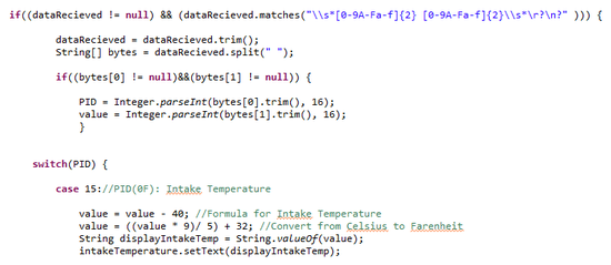
In order for the gauges and textViews to display data, we first needed a way to parse the incoming data from the Kiwi Bluetooth. The sample code below shows how we parsed the data for Intake Temperature and calculated the actual value.
As shown in the sample code, the use of regular expressions was used in order to parse the incoming data. The regular expression shown is to match incoming data of a two hex byte format such as "0F 5D." Once we are able to get a match with the incoming data, we then use String.trim() to remove any excess white space which will cause errors in calculations if not removed. Once we implemented the parsing code for Intake Temperature, we can apply the same methods to the other five parameters.
Given the nature of the ELM327 OBD to serial interpreter, it is hard to predict the incoming string format response. Therefore, many regular expression cases were implemented in order to match data more often. It is desired to match data as much as possible in order to display the change in values as real time as possible which was a goal of this project.
Once the incoming data has been retrieved, the data must be converted into different units based on parameters. Each PID based on the OBD-II have a specific conversion formula to give users the actual value. These formulas can be found here. After conversion has been complete, the data values will then be sent to the front end of the application.
Android Frontend
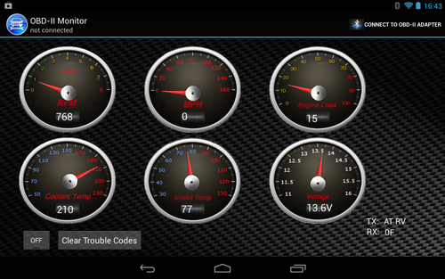
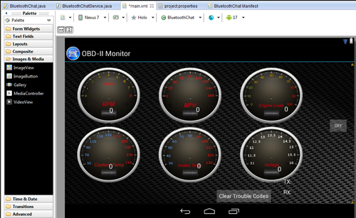
Figure 8 below displays the main page for the application.
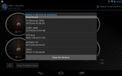
When opening up the application, the user must first connect to the PLX Kiwi by pressing on the button at the top right and selecting the device from the list (as shown in Figure 9). Once the tablet has successfully connected, you can start the gathering of parameter data by pressing on the toggleButton on the bottom left. The second button is to clear check engine codes (if any are present in the vehicle).
To make it easier for the user to read the current data of the vehicle, Android textViews were also inserted into the gauges to provide a numerical representation. This allows the user to quickly identify the value of each current parameter. There are also TX and RX field to display the information that the tablet is currently sending and receiving at that particular moment.
During the designing stage in the front end of the application, it was decided that the tablet would only have one screen to display the entire GUI. This was because implementing multiple screens would require the user to take his/her hands off the steering wheel, which could be potentially dangerous.
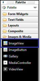
In terms of developing the front end of the application, there were two key elements to implement the GUI, creating the layout and creating the animations for the layout. There are many ways to make user interfaces as shown in Android's API Guides. In the OBD-II Android Monitor, the application GUI used ImageView to create the background and gauges for the GUI.
Before creating the layout, the layout orientation for the application was fixed to landscape. Modified in the AndroidManifest.xml file, using a landscape orientation provided a lower device profile as well as wider viewing angle. Figure 10 below shows the modification to set the layout to "landscape." If the application was to be portrait or can switch from both, then the orientation would be changed to "portrait" or "auto" respectively.
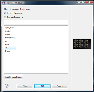
Once the file has been imported into the application, the image is then displayed into the workspace of the .xml file, as shown in Figure 13.
In order to create our gauges that will be used to display the vehicle data in real time. We created a custom gauge background with all of the parameters that we have chosen for the project with their appropriate data ranges for each. Once we had implemented the gauge dial backgrounds, the next step as the create the moving part which was the gauge needle. In order to do this, the use of an Android API called RotateAnimation was used. RotateAnimation was chosen as to create the gauge because it provided us with more flexibility when creating custom gauges. Continuing with the sample code for the parsing of Intake Temperature from the back end development, we can see how to RotateAnimation API is used in the code below.
From the sample code above, the Interpolator deals with the data rate of change. For circular gauges, we want the needles to move in a linear way. The setFillAfter(true) allows the gauge to stay at the final position. By default, RotateAnimation will rotate an image and then bring it back to it's previous position which isn't the desired behavior for gauges. More about the RotateAnimation API is detailed here.
Testing & Technical Challenges
Testing the Android Application
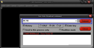
To test and debug the Android application during development, TeraTerm was used as a tool. TeraTerm is an open source terminal application program for Windows that can communicate with SPP devices. Figure 15. below shows a screenshot of the TeraTerm program.
To test the Android application for it's functionality. TeraTerm was used to send messages to the Nexus 7 over SPP to test if obtain the desired result. This helped to ensure that our regular expressions was correct and that there weren't any issues calculating data to be displayed on the gauges. The testing and debugging was mostly done through TeraTerm and once the team felt that there was significant progress added to the application functionality, then we would go out and test the application with the vehicle. It seemed very tedious to go out to the vehicle after every build, so TeraTerm helped out the team a lot with testing.
Issues with Getting Data From the ELM327
A big challenge in this project was to parse the incoming data sent by the ELM327. It created a challenge for us due to the inconsistency of format in the data. Examples of inconsistencies would be random added spaces, newlines, null characters, or split messages. The typical operation of the ELM327 is to send a command byte followed by a parameter ID (PID) such as "01 00" followed by a carriage return ('\r') byte.
For example, if we were to send the message to obtain intake temperature, we would send ("01 0F" + '\r') to the ELM327. And get a typical response back of:
- ELM327: 01 0F
- ELM327: 41 0F 5C
- ELM327:
- ELM327: >
OR
- ELM327: 01
- ELM327: 0F 4
- ELM327: 1 5C >
From the sample output above, the desired data that we need is the "5C" for this example. As you can see, the "5C" doesn't appear in a predictable manner which makes this a challenge to obtain the data we need. Note that these are only two samples of the possible message format.
To solve this problem, the use of Regular Expressions and built in Java String functions were used. The Java String functions that were utilized were trim(), split(), and matches(). The String.trim() allowed for us to remove any extra padded spaces in front and back of a string message received from the ELM327. String.split() allowed for us to split up the received string message into message bytes using space (" ") as a delimiter. It was desired to split up the received message since the data that follows the PID, is the data we want to retrieve. String.matches() functions by using Regular Expressions to check with selected data. If the data matches the corresponding regular expression then it is parsed, otherwise it is just simply ignored.
The regular expression pattern used to match for MPH, intake temperature, engine load, and coolant temperature was "\s*[0-9A-Fa-f]{2} [0-9A-Fa-f]{2}\s*\r?\n?".
A drawback of using String.matches() and regular expressions is that it is a "hit or miss" scenario. This is due to the fact that the message received will either match or not match with the given regular expression. To address this, all message possibilities must be addressed and accounted for with regular expressions. This is essential to the performance of our application because the more matches obtained will give the user a real time response.
Conclusion
Coming into this project, the team members had no experience with Java and Android application programming. With the 9 weeks given for the project, we were able to learn how to use the Android SDK to create an Android application. Our Android application is able to communicate with the PLX Kiwi Bluetooth and display the parameters in real time to the user. We were also able to create circular gauges from scratch to display information visually using the RotateAnimation API. Although we have had great success, we faced a lot of challenges through the implementation of the Android application. One of those challenges dealt with getting the BluetoothChat sample code to operate correctly with the tablet and an SPP device. Another challenge was to parse the data received from the PLX Kiwi which was solved using regular expressions. Lastly, the gauges needed to be constructed from scratch because after doing some research, the team found that there wasn't really any good APIs to use with the project.
For future work on this project, we can move further by adding more features such as the ability to read diagnostic trouble codes and explain what each code means. Also, we can have the functionality for a user to customize their home screen to select which parameters to display on the gauges. There is a lot of room for improvement with the Android application and the team looks forward to upgrading the application.
Project Video
CmpE146 F12 T6 Demonstration Video
Project Source Code
References
Acknowledgement
We would like the thank the following people for their contributions during this project:
- Preet Kang
- Michael Cox
- Christopher Tugangui
- Ryan Branche
References Used
- Setting up Android SDK
- OBD-II Parameter IDs
- PLX Kiwi Bluetooth Device Page
- Regular Expressions Wiki
- Regular Expressions Online Tester
