File list
From Embedded Systems Learning Academy
This special page shows all uploaded files.
First page |
Previous page |
Next page |
Last page |
| Date | Name | Thumbnail | Size | Description | Versions |
|---|---|---|---|---|---|
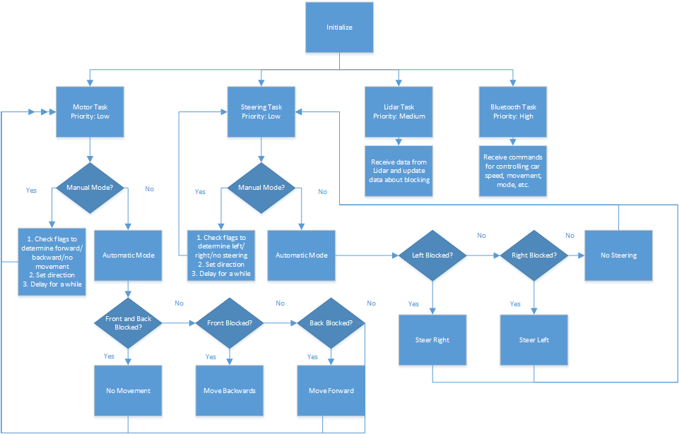
| 21:41, 20 December 2014 | 146statemachine.png (file) |  |
39 KB | 2 | |
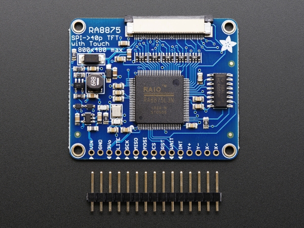
| 02:04, 24 May 2018 | 1590-08.jpg (file) |  |
272 KB | 1 | |
| 19:46, 17 December 2020 | Acceleration Registers.png (file) | 14 KB | 1 | ||
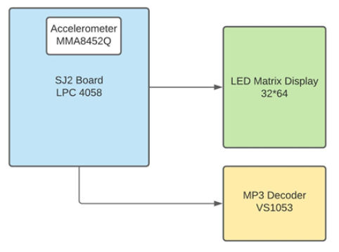
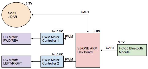
| 22:54, 17 December 2020 | Block Diagram TnJ.png (file) |  |
37 KB | 2 | |
| 22:32, 20 December 2016 | BluetoothModule-Hardware-Connections.png (file) |  |
31 KB | 4 | |
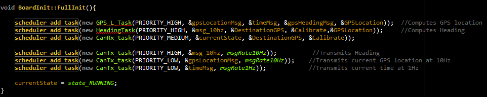
| 10:20, 22 December 2014 | BoardInit.png (file) | 20 KB | 1 | ||
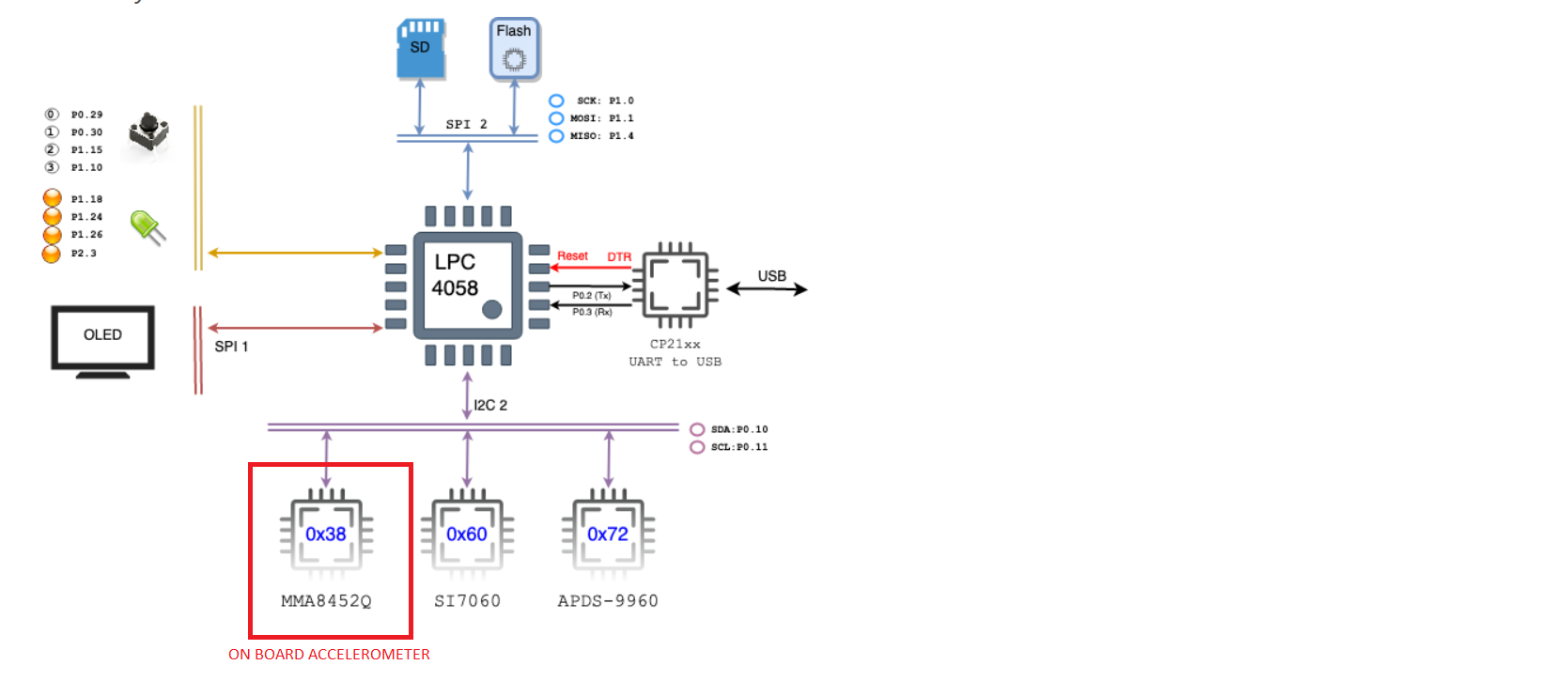
| 19:45, 17 December 2020 | Board Layout.png (file) |  |
102 KB | 2 | |
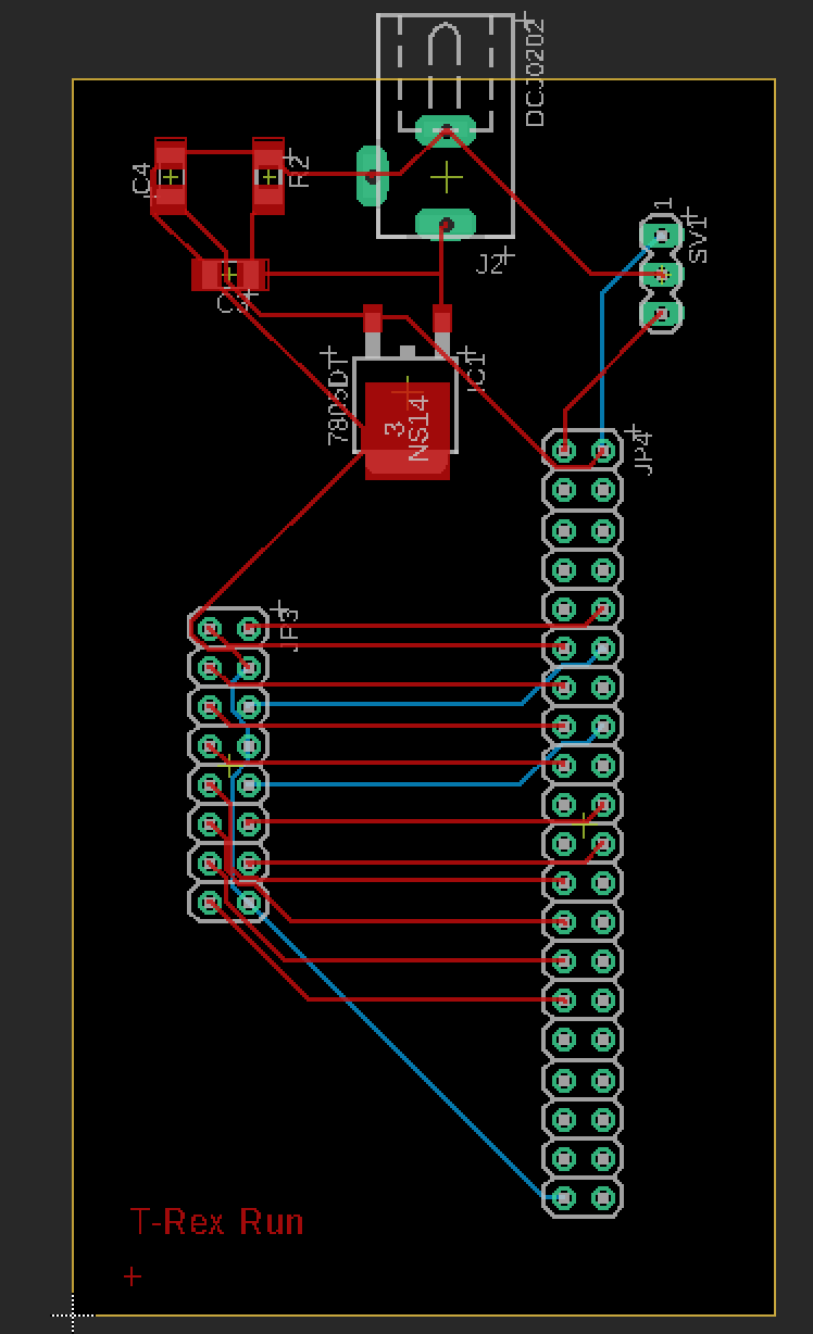
| 18:52, 25 November 2019 | Brd.png (file) |  |
68 KB | 1 | |
| 00:27, 22 December 2014 | CMPE146 F14 LidarGroup Hardware.jpg (file) |  |
18 KB | 1 | |
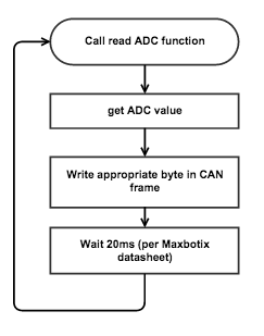
| 21:42, 20 December 2014 | CMPE146 F14 LidarGroup SoftwareStateMachine2.png (file) |  |
39 KB | 1 | |
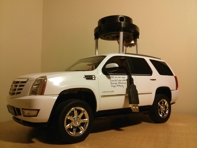
| 06:47, 22 December 2014 | CMPE146 F14 LidarGroup Vehicle1.jpg (file) |  |
81 KB | 1 | |
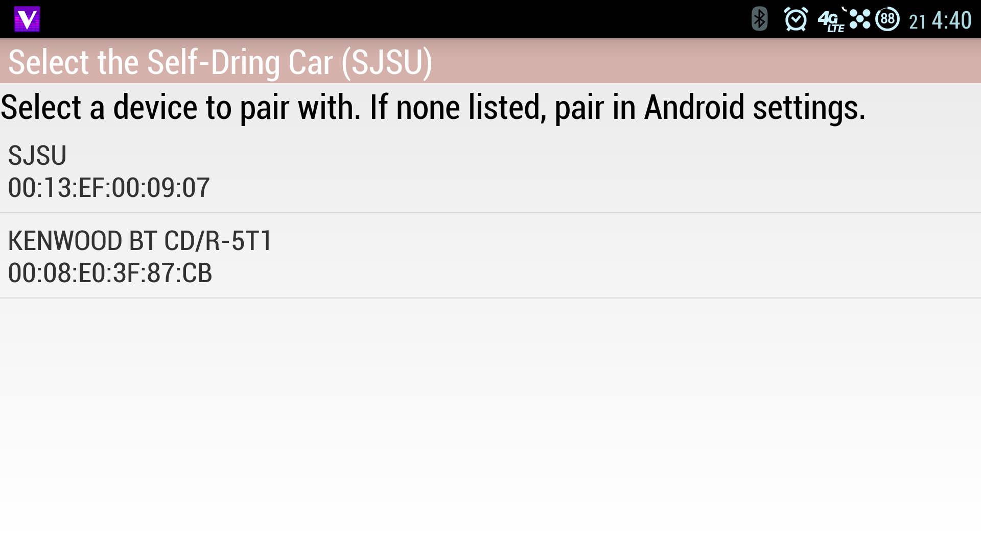
| 07:28, 22 December 2014 | CMPE243 F14 TeamUndergrad Android1.jpg (file) |  |
77 KB | 1 | |
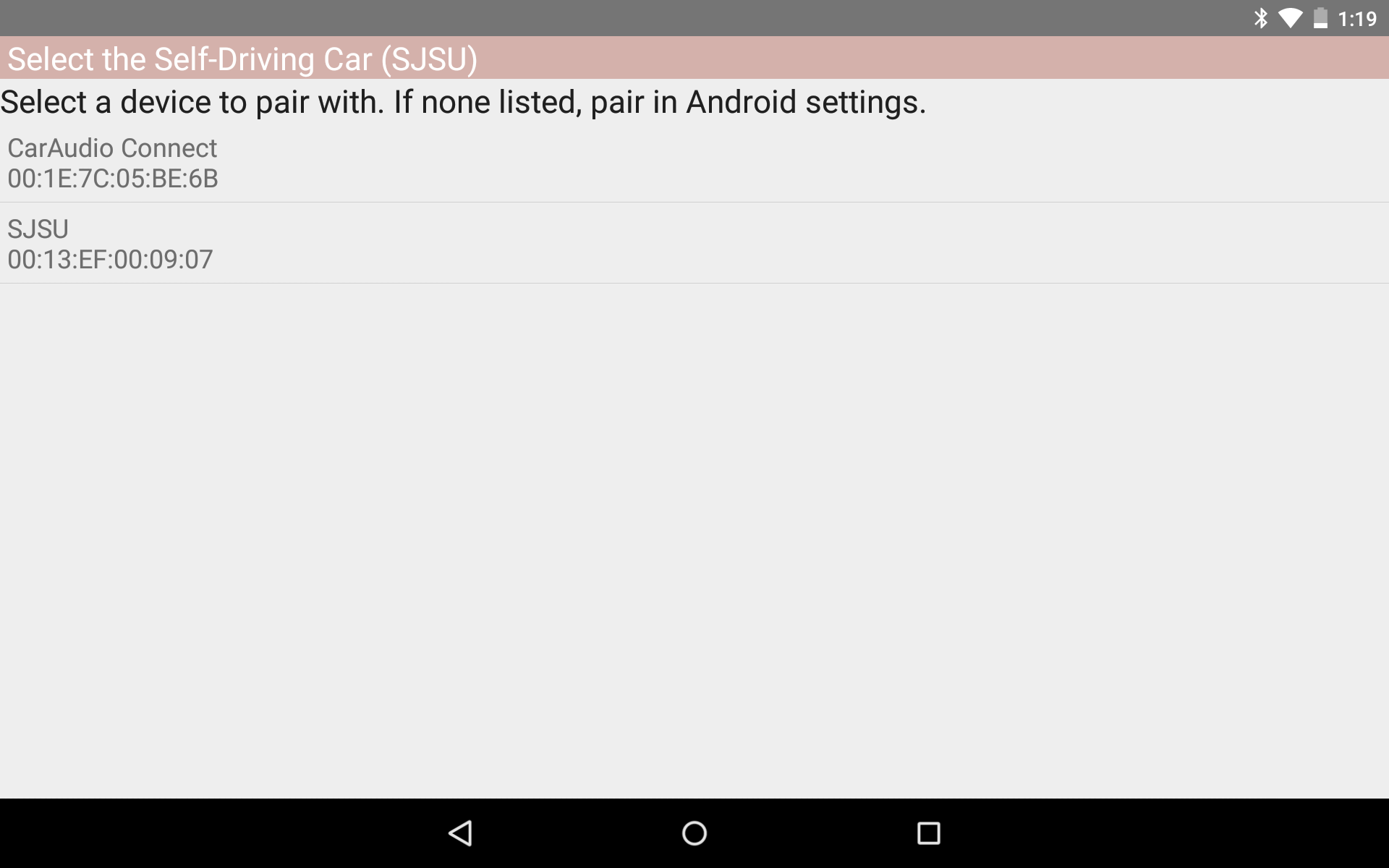
| 09:23, 22 December 2014 | CMPE243 F14 TeamUndergrad Android1.png (file) |  |
67 KB | 1 | |
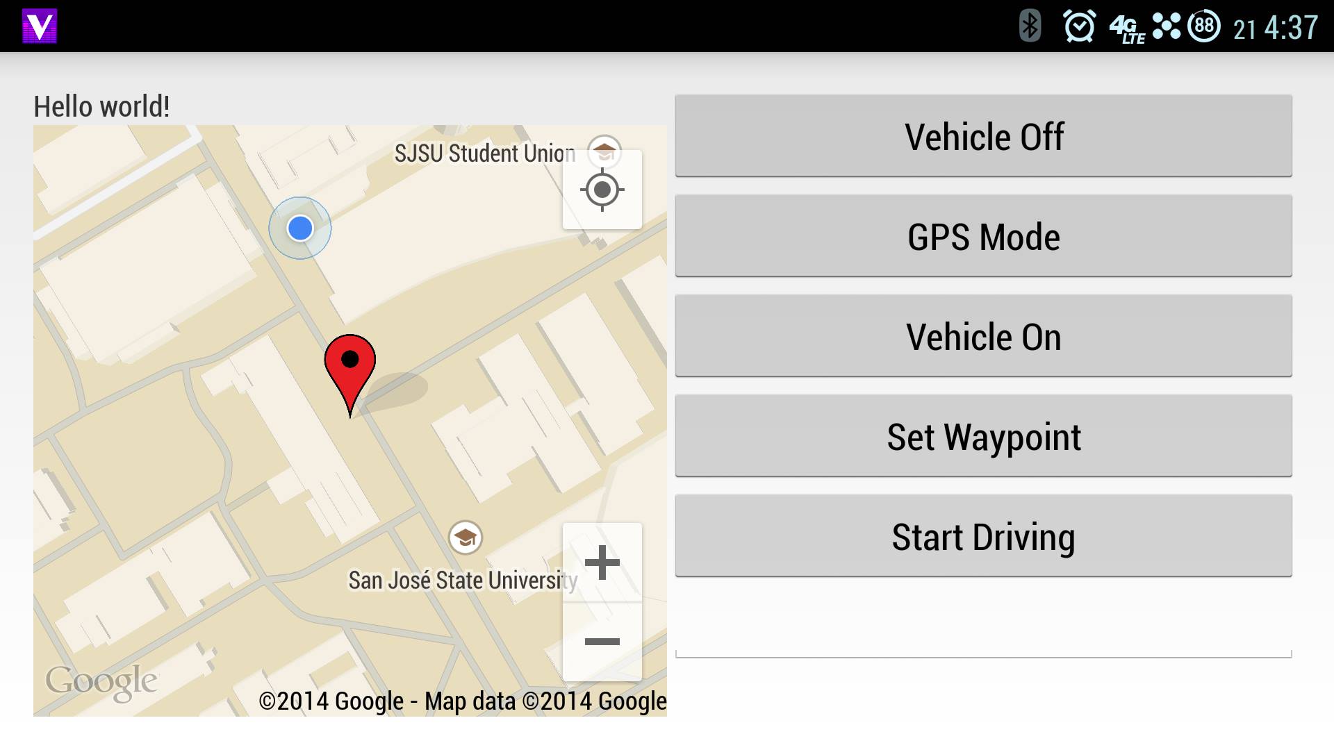
| 07:29, 22 December 2014 | CMPE243 F14 TeamUndergrad Android2.jpg (file) |  |
110 KB | 1 | |
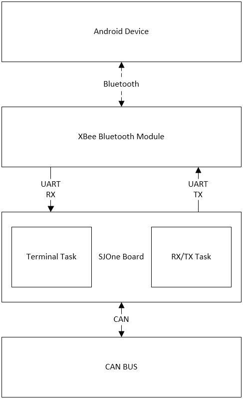
| 06:39, 22 December 2014 | CMPE243 F14 TeamUndergrad BridgeHighLevel.png (file) |  |
19 KB | 1 | |
| 22:59, 21 December 2014 | CMPE243 F14 TeamUndergrad IOSoftwareInterface.png (file) |  |
27 KB | 2 | |
| 03:04, 22 December 2014 | CMPE243 F14 TeamUndergrad motor sw interface.png (file) |  |
30 KB | 1 | |
| 09:25, 22 December 2014 | CMPE243 F14 sensorFlow1.png (file) |  |
33 KB | 1 | |
| 09:35, 22 December 2014 | CMPE243 F14 sensorFlow1j.jpg (file) |  |
49 KB | 1 | |
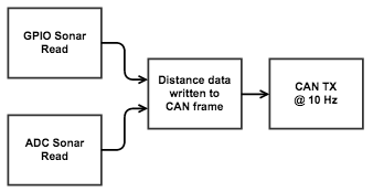
| 09:50, 22 December 2014 | CMPE243 F14 sonarFlow2.png (file) |  |
18 KB | 1 | |
| 09:52, 22 December 2014 | CMPE243 F14 sonarFlow3.png (file) |  |
15 KB | 1 | |
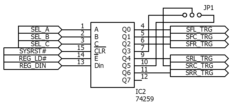
| 21:36, 20 December 2016 | CMPE243 F15 The Nine US-259.png (file) |  |
19 KB | I/O expander, register | 1 |
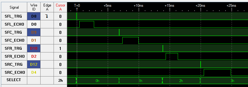
| 20:13, 22 December 2016 | CMPE243 F16 The-Nine Analyzer Cap.png (file) |  |
9 KB | 2 | |
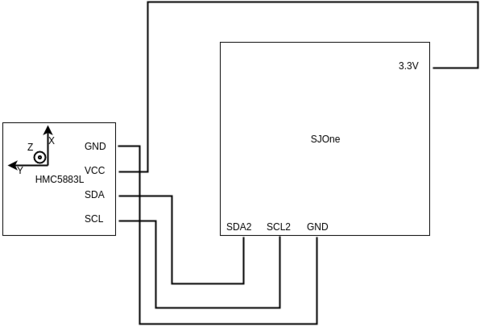
| 19:55, 22 December 2016 | CMPE243 F16 The-Nine compass schematic 480.png (file) |  |
13 KB | 1 | |
| 20:08, 22 December 2016 | CMPE243 F16 The-Nine destination-interface 360.gif (file) |  |
1.06 MB | Reverted to version as of 12:36, 22 December 2016 (CST) | 4 |
| 18:08, 22 December 2016 | CMPE243 F16 The-Nine google-maps-waypoint-anim 360.gif (file) |  |
825 KB | 1 | |
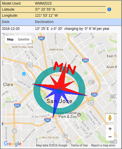
| 19:55, 22 December 2016 | CMPE243 F16 The-Nine magnetic declination 480.png (file) |  |
250 KB | 1 | |
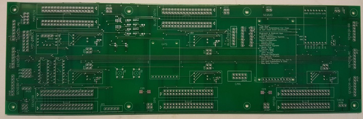
| 18:09, 22 December 2016 | CMPE243 F16 The-Nine manufactured-pcb 720.jpg (file) |  |
78 KB | 1 | |
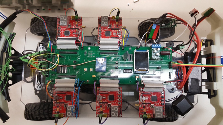
| 18:09, 22 December 2016 | CMPE243 F16 The-Nine populated-pcb 720.jpg (file) |  |
143 KB | 1 | |
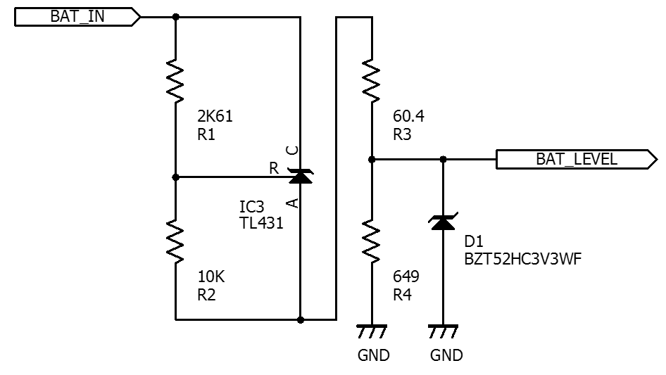
| 23:12, 20 December 2016 | CMPE243 F16 The Nine Battery Monitor.png (file) |  |
16 KB | Battery voltage monitor | 1 |
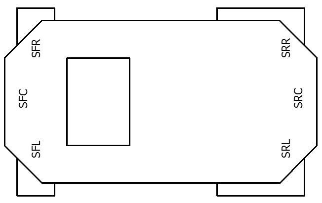
| 22:50, 20 December 2016 | CMPE243 F16 The Nine Car Outline.png (file) |  |
7 KB | Car outline with sensors | 2 |
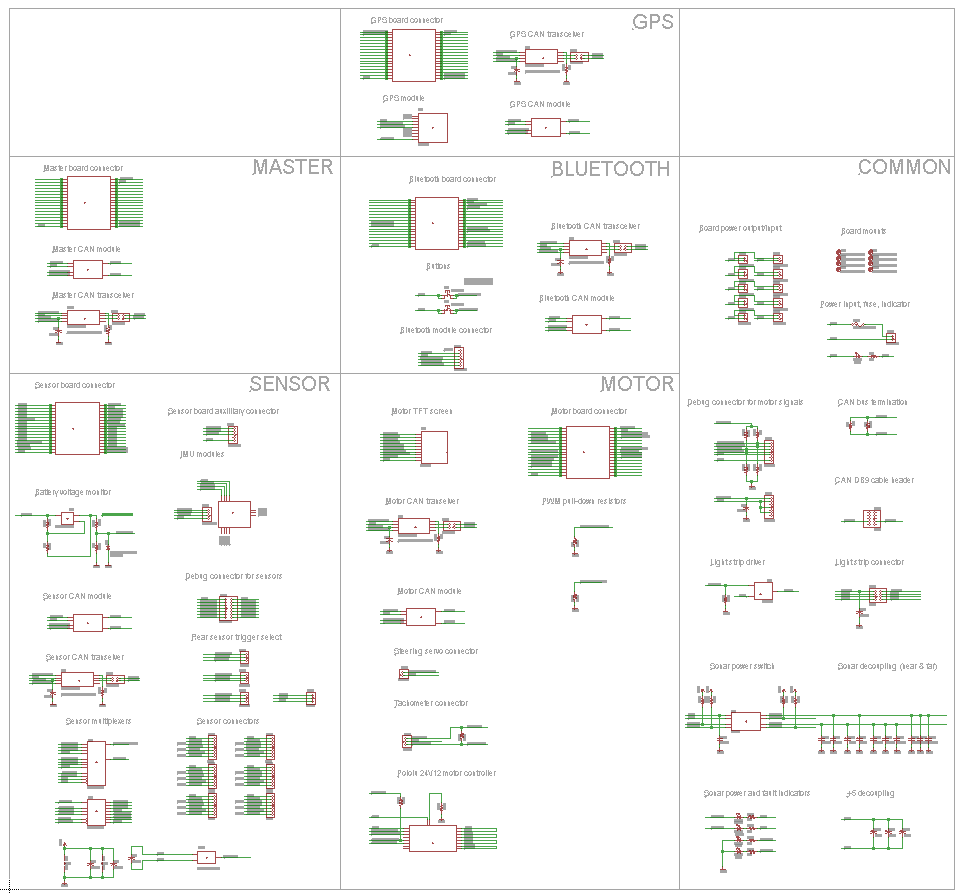
| 00:47, 21 December 2016 | CMPE243 F16 The Nine SCH.png (file) |  |
46 KB | Schematic diagram of PCB | 1 |
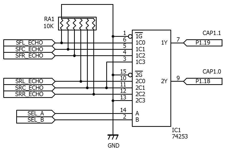
| 21:22, 20 December 2016 | CMPE243 F16 The Nine US-253.png (file) |  |
26 KB | Schematic image of I/O expander | 1 |
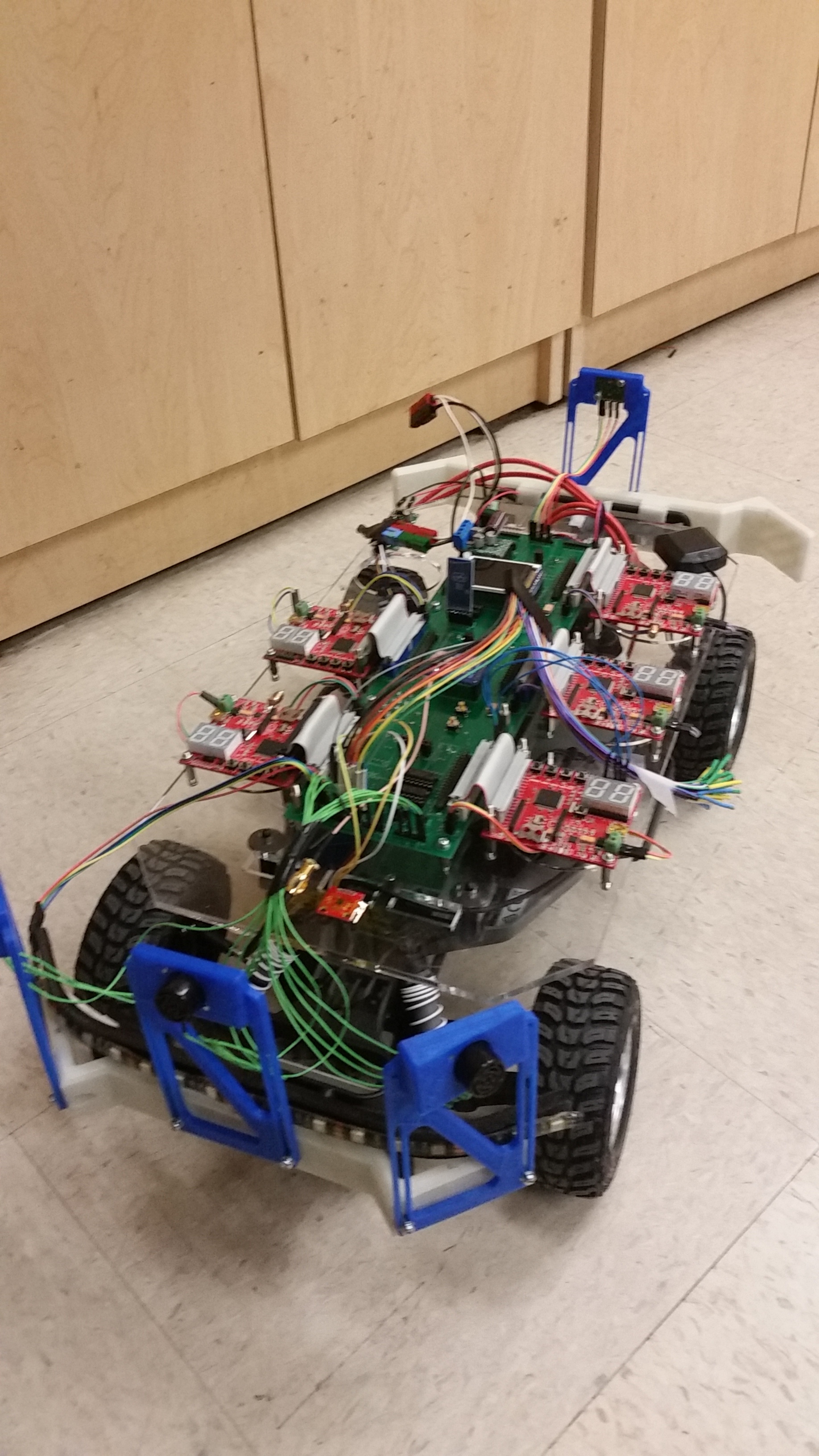
| 00:46, 21 December 2016 | CMPE243 S16 The Nine Top Right View.jpg (file) |  |
1.48 MB | 1 | |
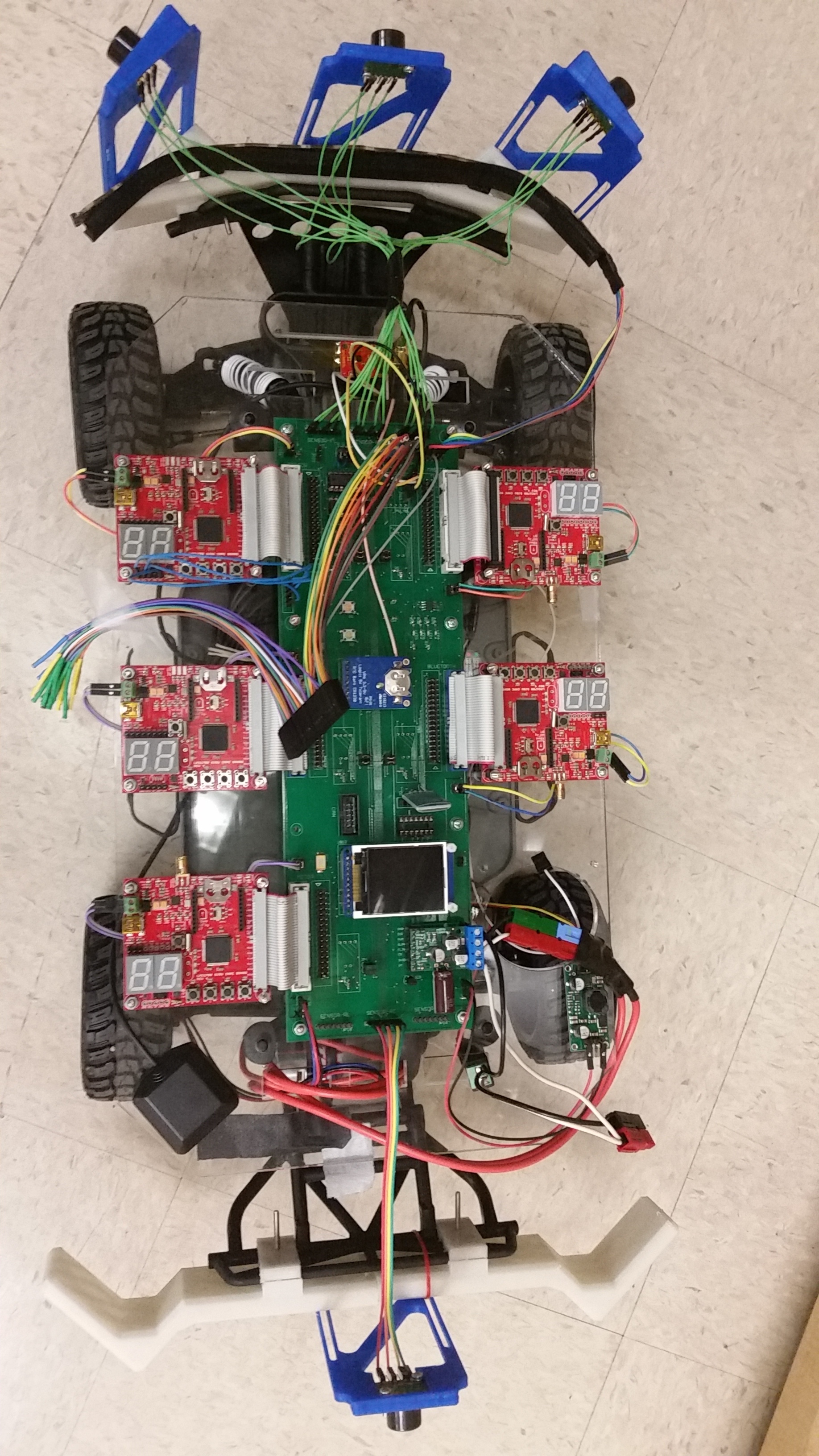
| 00:46, 21 December 2016 | CMPE243 S16 The Nine Top View.jpg (file) |  |
1.75 MB | 1 | |
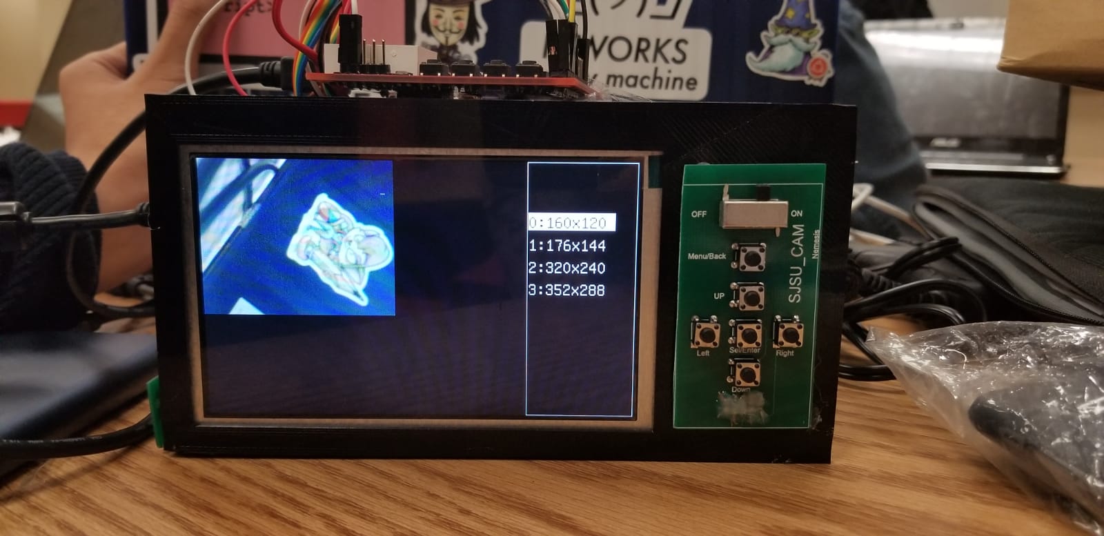
| 21:40, 24 May 2018 | CMPE244 Nemesis Cam.jpeg (file) |  |
125 KB | 1 | |
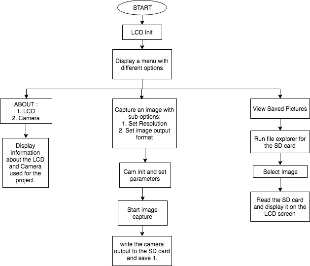
| 19:19, 23 May 2018 | CMPE244 Nemesis Flowchart.jpg (file) |  |
42 KB | 1 | |
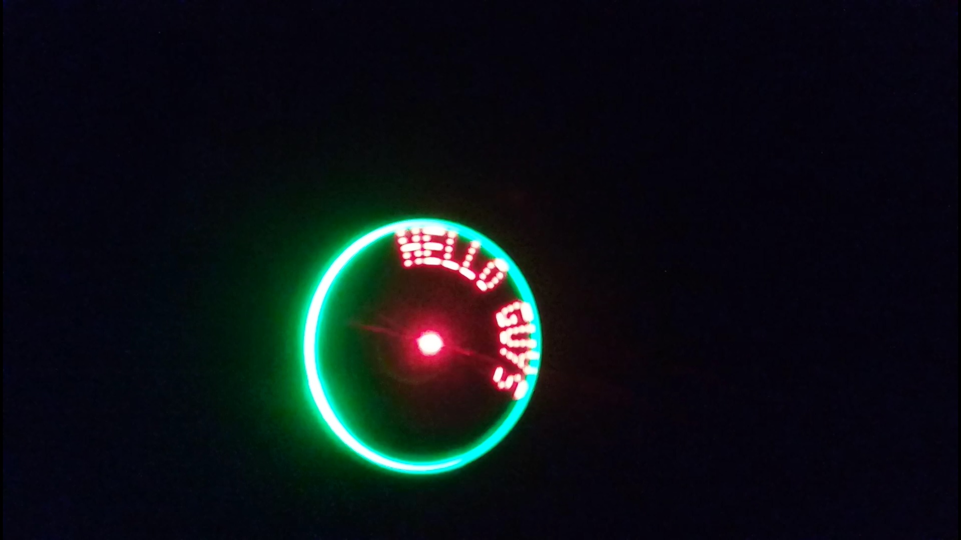
| 00:27, 26 May 2017 | CMPE244 S17 POVClock Output1.jpg (file) |  |
175 KB | Characters on POV display | 1 |
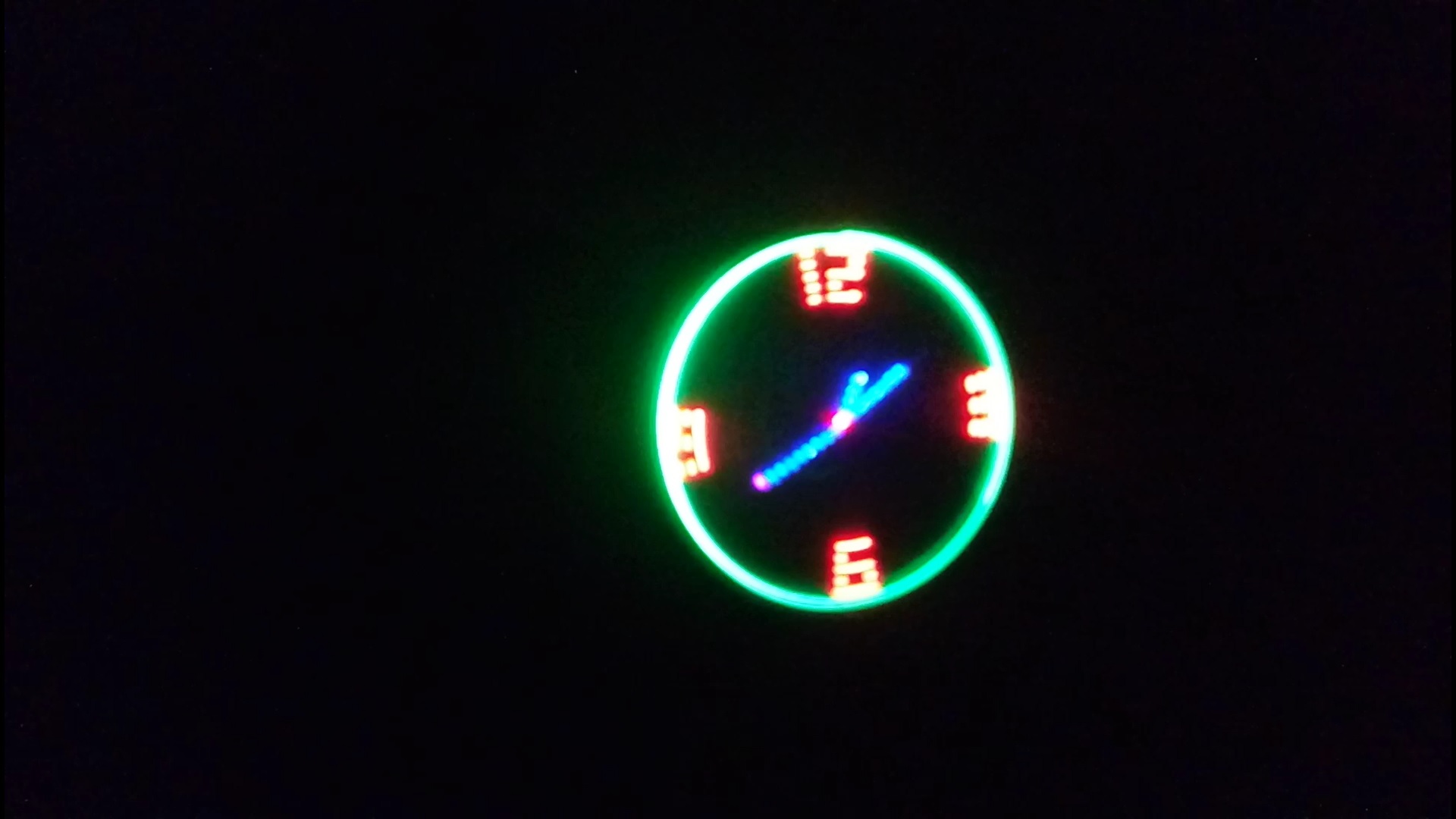
| 00:26, 26 May 2017 | CMPE244 S17 POVClock Output2.jpg (file) |  |
157 KB | Analog clock output | 1 |
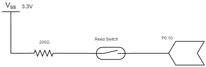
| 21:40, 25 May 2017 | CMPE244 S17 ReedSwitch connection.jpg (file) |  |
13 KB | Reed Switch Connection Diagram | 1 |
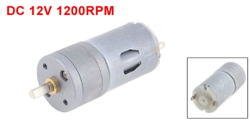
| 00:20, 22 May 2017 | CMPE244 S17 povclock DCmotor.jpg (file) |  |
14 KB | DC Motor High Torque | 1 |
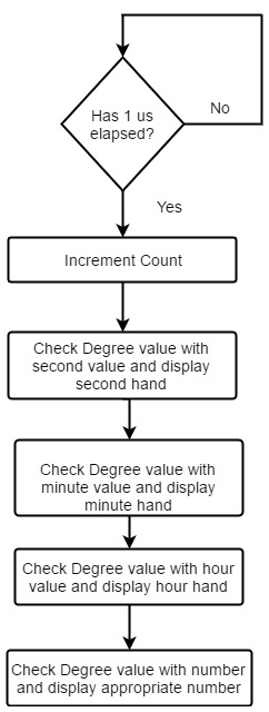
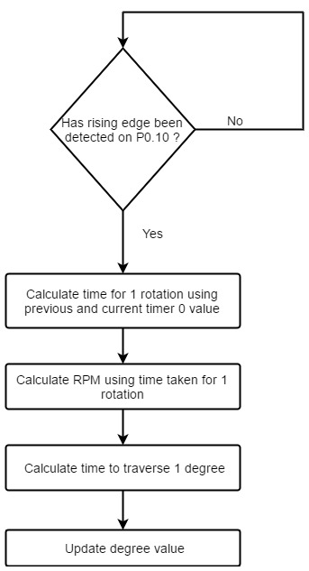
| 22:12, 25 May 2017 | CMPE244 S17 povclock Timer0 flow graph.jpg (file) |  |
39 KB | Timer 0 Flow Graph | 2 |
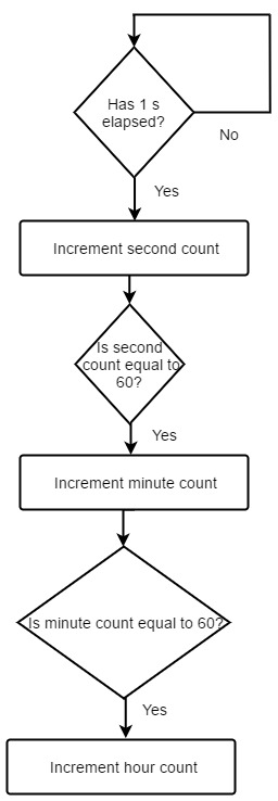
| 22:01, 25 May 2017 | CMPE244 S17 povclock Timer1 flow graph.jpg (file) |  |
30 KB | Flow Graph - Timer1 | 1 |
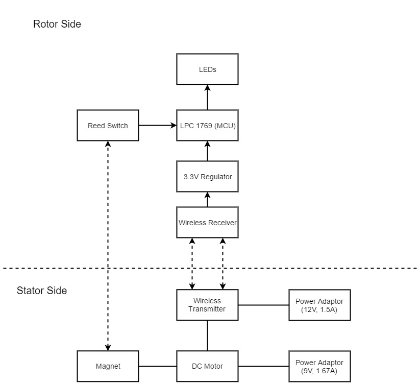
| 21:48, 25 May 2017 | CMPE244 S17 povclock block diagram.jpg (file) |  |
47 KB | System Block Diagram | 1 |
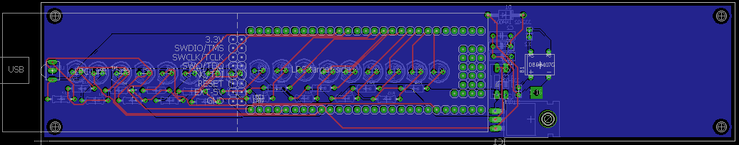
| 08:48, 21 May 2017 | CMPE244 S17 povclock brd.PNG (file) | 32 KB | PCB Board Layout | 1 | |
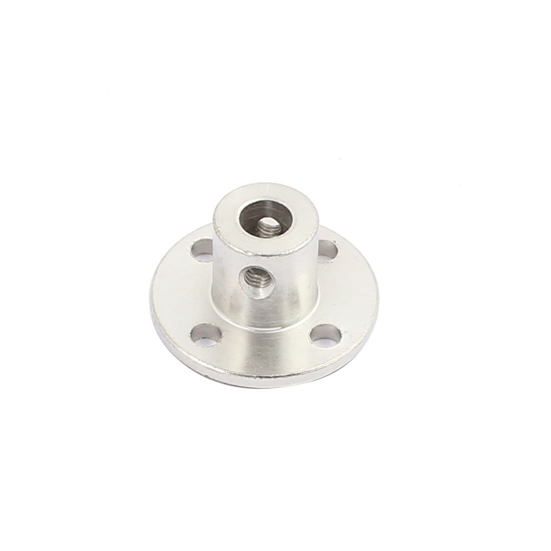
| 03:18, 22 May 2017 | CMPE244 S17 povclock coupler.jpg (file) |  |
37 KB | Shaft Coupler/connector | 1 |
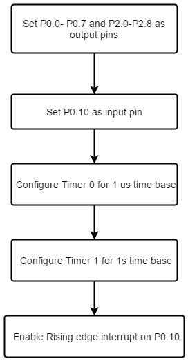
| 21:59, 25 May 2017 | CMPE244 S17 povclock external interrupt.jpg (file) |  |
35 KB | Flow graph- External Interrupt | 1 |
| 21:59, 25 May 2017 | CMPE244 S17 povclock initialization.jpg (file) |  |
27 KB | Flow Graph - initialization | 1 |
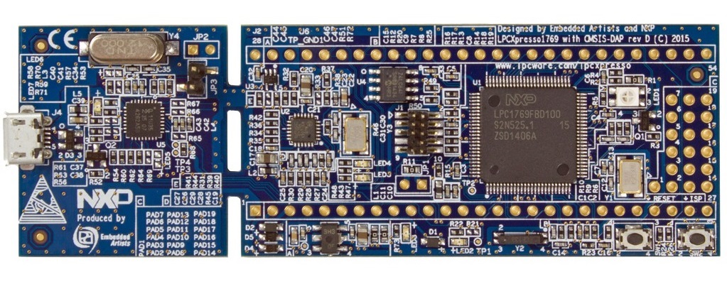
| 01:33, 22 May 2017 | CMPE244 S17 povclock lpc1769.jpg (file) |  |
220 KB | Embedded Artist LPCXpresso LPC1769 | 1 |
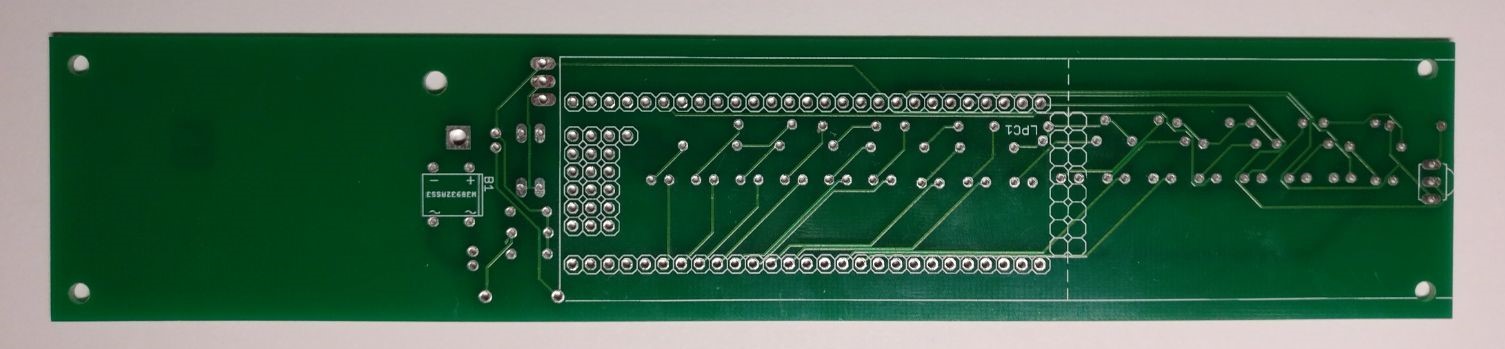
| 21:16, 25 May 2017 | CMPE244 S17 povclock pcb LPC.jpeg (file) | 109 KB | PCB side containing LPC1769 | 1 |
First page |
Previous page |
Next page |
Last page |