Difference between revisions of "S22: Road Runner"
(→Technical Challenges) |
(→Hardware Design) |
||
| Line 851: | Line 851: | ||
=== Hardware Design === | === Hardware Design === | ||
| − | {| class="wikitable" style="text-align: center; width: | + | {| class="wikitable" style="text-align: center; width: 400px; height: 300px;" |
! SJTwo board Pin | ! SJTwo board Pin | ||
! Device | ! Device | ||
| Line 870: | Line 870: | ||
|- | |- | ||
|} | |} | ||
| + | |||
=== Software Design === | === Software Design === | ||
Revision as of 04:17, 28 May 2022
Contents
Road Runner
Abstract
!!! MAKE SURE YOU BUY AN RC CAR THAT HAS RELIABLE PWM ESC AND A BUILT-IN RPM SENSING MECHANISM !!!
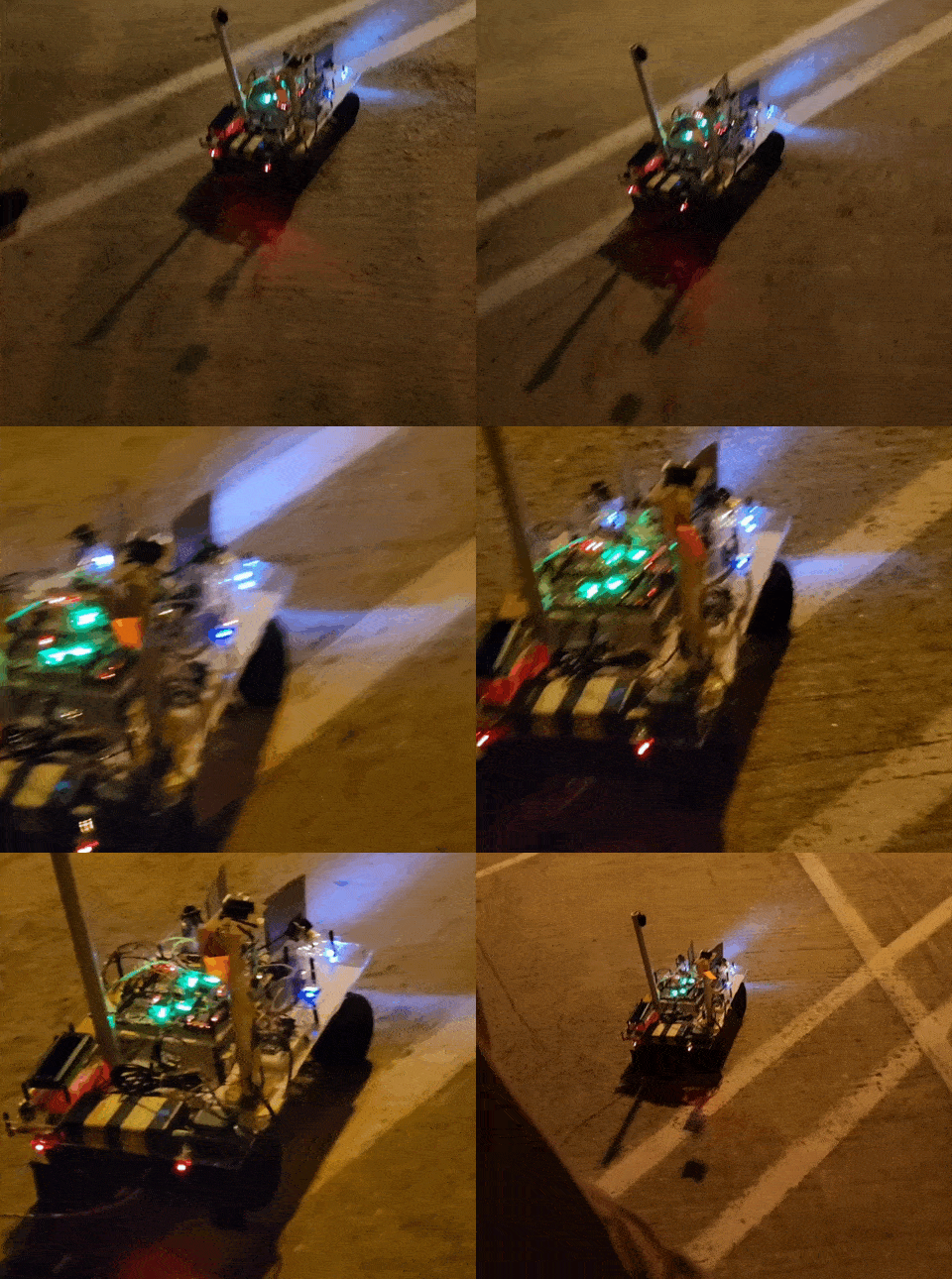
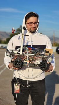
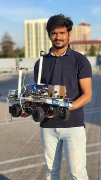
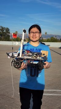
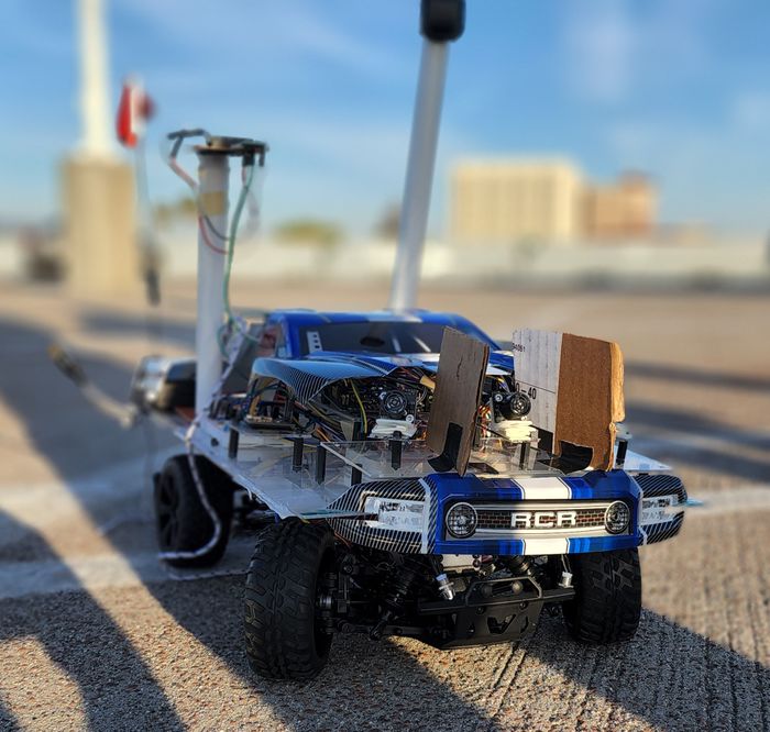
Road Runner is a self navigating car built with the ability to drive to a specified geo-location within its battery range, while avoiding any physical obstacles that come on its way and successfully reaching its destination, with no human intervention apart from commanding the destination location . The car’s infrastructure has four important nodes (Driver, Sensor and Bridge, Geo and Motor) communicating within themselves over internal CAN Bus and with the end user over a mobile application. The car always strives to stay on and maintain its path to the destination by periodically sensing and processing all the relevant information from the nodes to arrive at an informed decision. It is built on top of a hobby grade RC car chassis with all the necessary adjustments and components to achieve its intended objective of self navigating and object avoidance, one of the basic requirements and functionality of an autonomous vehicle.
Introduction
The project was divided into 5 modules:
- Bridge and Sensor Controller
- Motor Controller
- Geo Controller
- Driver / LCD Controller
- Android app interface
Team Members & Responsibilities
Road Runner Firmware: GitLab Repo
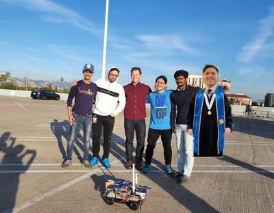
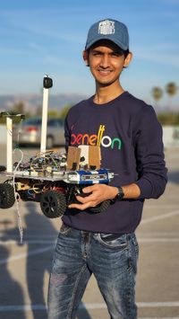
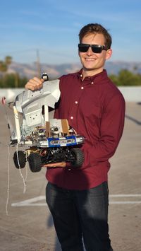
Team Members:
- Dhruv Choksi
- Jonathan Doctolero
- Tudor Donca
- Hisaam Hashim
- Saicharan Kadari [1]
- Kyle Kwong
Project Subteams:
- Bridge and Sensor Controller:
- Tudor Donca
- Saicharan Kadari
- Motor Controller:
- Dhruv Choksi
- Hisaam Hashim
- Geological Controller:
- Kyle Kwong
- Jonathan Doctolero
- Saicharan Kadari
- Driver and LCD Controller:
- Hisaam Hashim
- Kyle Kwong
- Android Application:
- Jonathan Doctolero
- Tudor Donca
- Integration and System Testing:
- Tudor Donca
- Dhruv Choksi
- Hisaam Hashim
- Saicharan Kadari
- Kyle Kwong
- Jonathan Doctolero
Schedule
| Week# | Start Date | End Date | Task | Status |
|---|---|---|---|---|
| 1 | 03/06/2022 | 03/12/2022 |
|
|
| 2 | 03/13/2022 | 03/19/2022 |
|
|
| 3 | 03/20/2022 | 03/26/2022 |
|
|
| 4 | 03/27/2022 | 04/02/2022 |
|
|
| 5 | 04/03/2022 | 04/09/2022 |
|
|
| 6 | 04/10/2022 | 04/16/2022 |
|
|
| 7 | 04/17/2022 | 04/23/2022 |
|
|
| 8 | 04/24/2022 | 04/30/2022 |
|
|
| 9 | 05/01/2022 | 05/07/2022 |
|
|
| 10 | 05/08/2022 | 05/15/2022 |
|
|
| 11 | 05/05/2022 | 05/24/2022 |
|
|
| 11 | 05/25/2022 | 05/25/2022 |
|
|
Parts List & Cost
| Item# | Part Description | Vendor | Qty | Cost |
|---|---|---|---|---|
| 1 | RC Car | Redcat [2] | 1 | $153.00 |
| 2 | CAN Transceivers | Various | 6 | $55 |
| 3 | Ultrasonic Sensors | Max Botix[3] | 3 | $134.00 |
| 4 | Adafruit Bluetooth UART Tranceiver | Adafruit[4] | 1 | $33.90 |
| 5 | GPS Module and Antenna | Adafruit[5][6] | 1 | $59.50 |
| 6 | Compass Module | Adafruit[7] | 1 | $29.00 |
| 7 | Wheel Speed RPM Encoder | 1 | ||
| 8 | Discrete Electronic Components | Generic[8] | 1 | $ |
Electrical Wiring and Powering the System
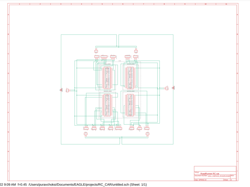
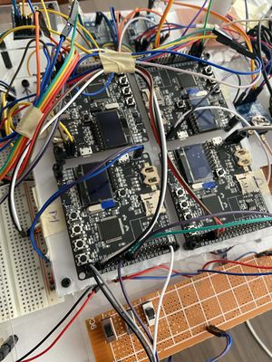
Below is the schematic of our RC car. We have tried to keep it simple and self-explanatory so that anyone referring this report can easily trace the connections and understand it.
Power Management
We have used two batteries, one for the RC car which is 7.4V Lipo battery and the other is 5V,2A power bank. The Lipo battery powered the RC card for us and the power bank powered all the SJ2 boards and the peripherals used.
Challenges
The three main challenges we faced with electrical wiring are:
1. Cable Management: Due to large number of wire connections, we faced difficulty in routing and managing all the wires.
2. Component’s placement and orientation: It is very important where you place your components to minimize the wire length and make it more manageable. Except the ultrasonic sensors, almost every other component can be placed anywhere so that you can route the wires easily. We couldn’t figure out the positions at early stage and so we struggled.
3. Power Management: It is one of the most important aspect of electrical wiring. It is most important to supply components with the stable rated power. We took quite some time in finalizing our power management.
Advice
o Read the previous year reports and try to fix the components position before hand and try to make the plug and play kind of prototype board so that you don’t waste your time connecting the components again and again. Doing so will help you focus more on your improvising your software later and make it more reliable and accurate.
o Make a separate power supply for your peripherals and the SJ2 board (preferable avoid using the RC car’s battery).
o Make the pcb/prototype board plug and play so that it’s easy to replace the components if needed.
o We highly recommend you just power all the boards and peripherals at 5V from a simple phone charger bank. Just make sure all your components can handle 5V. This way you can avoid the complications of using a voltage regulator. We had a lot of trouble with voltage regulators breaking and subtly malfunctioning throughout the semester. Keep it simple!
CAN Communication
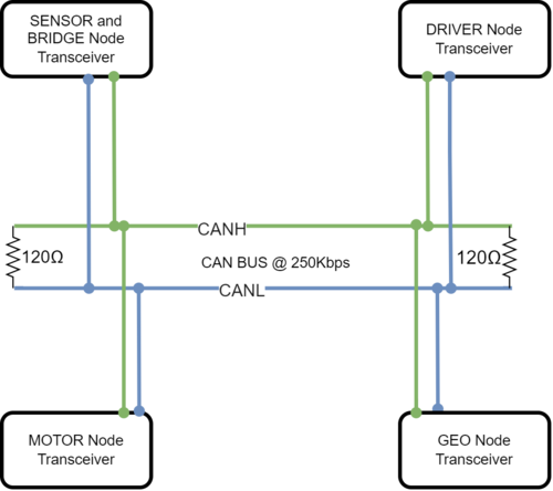
We used CAN Communication setup between all the nodes of the RoadRunner setup. This CAN Bus is terminated with the use of two 120 ohm resistors at both the ends of the Bus. Message IDs were chosen based upon an agreed priority scheme and Bus arbitration scheme. We assigned high priority IDs to messages that controlled the motor, thereby controlling the actual physical movement of the car, followed by sensor and GEO messages, and lowest priority messages were for debug and status messages from the respective nodes . More technical details to fill in..
Hardware Design
DBC File
Gitlab link to the RoadRunner DBC file
VERSION ""

NS_ :
     BA_
     BA_DEF_
     BA_DEF_DEF_
     BA_DEF_DEF_REL_
     BA_DEF_REL_
     BA_DEF_SGTYPE_
     BA_REL_
     BA_SGTYPE_
     BO_TX_BU_
     BU_BO_REL_
     BU_EV_REL_
     BU_SG_REL_
     CAT_
     CAT_DEF_
     CM_
     ENVVAR_DATA_
     EV_DATA_
     FILTER
     NS_DESC_
     SGTYPE_
     SGTYPE_VAL_
     SG_MUL_VAL_
     SIGTYPE_VALTYPE_
     SIG_GROUP_
     SIG_TYPE_REF_
     SIG_VALTYPE_
     VAL_
     VAL_TABLE_

BS_:

BU_: DBG DRIVER MOTOR SENSOR_BRIDGE GEOLOGICAL

BO_ 100 MOTOR_CMD: 4 DRIVER
 SG_ MOTOR_steer_direction : 0|9@1- (1,-2) [-2|2] "steer direction" MOTOR
 SG_ MOTOR_speed_kph : 9|20@1- (0.1,-10.1) [-10.1|10.1] "kph" MOTOR
 SG_ MOTOR_drive_mode : 29|3@1+ (1,0) [0|0] "mode" MOTOR

BO_ 101 MOTOR_STATUS: 4 MOTOR
 SG_ actual_steer_degrees : 0|9@1- (1,-2) [-2|2] "steer direction" DRIVER,DBG
 SG_ actual_speed_kph : 9|20@1- (0.1,-10.1) [-10.1|10.1] "kph" DRIVER,DBG
 SG_ actual_drive_mode : 29|3@1+ (1,0) [0|0] "mode" DRIVER,DBG

BO_ 102 MOTOR_TEST_CONTROL_OVERRIDE: 8 DBG
 SG_ override_steer_pwm : 0|24@1+ (0.01,0) [5.01|15.01] "duty" MOTOR
 SG_ override_motor_pwm : 24|24@1+ (0.01,0) [5.01|15.01] "duty" MOTOR
 SG_ override_enable : 48|1@1+ (1,0) [0|1] "flag" MOTOR

BO_ 200 SENSOR_SONARS: 8 SENSOR_BRIDGE
 SG_ SENSOR_SONARS_left : 0|10@1+ (1,0) [0|500] "cm" DRIVER
 SG_ SENSOR_SONARS_right : 10|10@1+ (1,0) [0|500] "cm" DRIVER
 SG_ SENSOR_SONARS_middle : 20|10@1+ (1,0) [0|500] "cm" DRIVER
 SG_ SENSOR_SONARS_back : 30|10@1+ (1,0) [0|500] "cm" DRIVER

BO_ 201 GPS_DESTINATION: 8 SENSOR_BRIDGE
 SG_ GPS_DESTINATION_latitude : 0|28@1- (0.000001,-90.000000) [-90|90] "Degrees" GEOLOGICAL
 SG_ GPS_DESTINATION_longitude : 28|28@1- (0.000001,-180.000000) [-180|180] "Degrees" GEOLOGICAL

BO_ 202 WAYPOINT: 8 SENSOR_BRIDGE
 SG_ WAYPOINT_latitude : 0|28@1- (0.000001,-90.000000) [-90|90] "Degrees" GEOLOGICAL
 SG_ WAYPOINT_longitude : 28|28@1- (0.000001,-180.000000) [-180|180] "Degrees" GEOLOGICAL

BO_ 203 BRIDGE_CAR_CONTROL: 8 SENSOR_BRIDGE
 SG_ DRIVER_start_stop : 0|1@1+ (1,0) [0|1] "" DRIVER

BO_ 350 GEO_STATUS: 8 GEOLOGICAL
 SG_ GEO_STATUS_COMPASS_HEADING : 0|12@1+ (1,0) [0|359] "Degrees" DRIVER,SENSOR_BRIDGE
 SG_ GEO_STATUS_COMPASS_BEARING : 12|12@1+ (1,0) [0|359] "Degrees" DRIVER,SENSOR_BRIDGE
 SG_ GEO_STATUS_DISTANCE_TO_DESTINATION : 24|24@1+ (1,0) [0|0] "Meters" DRIVER,SENSOR_BRIDGE

BO_ 360 GEO_CURRENT_POSITION: 8 GEOLOGICAL
 SG_ GEO_CURRENT_POSITION_latitude : 0|28@1- (0.000001,-90.000000) [-90|90] "Degrees" DRIVER,SENSOR_BRIDGE
 SG_ GEO_CURRENT_POSITION_longitude : 28|28@1- (0.000001,-180.000000) [-180|180] "Degrees" DRIVER,SENSOR_BRIDGE

BO_ 500 DEBUG_SENSOR_BRIDGE: 8 SENSOR_BRIDGE
 SG_ sensor_left_raw_value : 0|12@1+ (1,0) [0|0] "" DBG
 SG_ sensor_right_raw_value : 12|12@1+ (1,0) [0|0] "" DBG
 SG_ sensor_middle_raw_value : 24|12@1+ (1,0) [0|0] "" DBG
 SG_ sensor_back_raw_value : 36|12@1+ (1,0) [0|0] "" DBG

BO_ 505 DEBUG_MOTOR_CONTROL: 8 MOTOR
 SG_ target_steer_direction : 0|8@1- (1,-2) [-2|2] "steer direction" DBG
 SG_ target_speed_kph : 8|12@1- (0.1,-10.1) [-10.1|10.1] "kph" DBG
 SG_ current_raw_motor_pwm : 20|20@1+ (0.01,0) [5.01|15.01] "duty" DBG
 SG_ current_raw_servo_pwm : 40|20@1+ (0.01,0) [5.01|15.01] "duty" DBG
 SG_ is_override_enabled : 60|1@1+ (1,0) [0|1] "flag" DBG

BO_ 506 DEBUG_MOTOR_RPM: 8 MOTOR
 SG_ computed_rpm : 0|12@1+ (1,0) [0|4000] "rpm" DBG
 SG_ computed_kph : 12|12@1- (0.1,-10.1) [-10.1|10.1] "kph" DBG
 SG_ computed_pid_increment : 24|20@1- (0.01,-5.01) [-5.01|5.01] "duty" DBG
 SG_ total_encoder_tick_count : 44|20@1+ (1,0) [0|0] "ticks" DBG

BO_ 510 DEBUG_DRIVER: 8 DRIVER
 SG_ driver_intention : 0|8@1+ (1,0) [0|0] "" DBG
 SG_ driver_steer_direction : 8|8@1+ (1,0) [0|0] "" DBG
 SG_ driver_drive_direction : 16|8@1+ (1,0) [0|0] "" DBG

CM_ BU_ DRIVER "The driver controller driving the car";
CM_ BU_ MOTOR "The motor controller of the car";
CM_ BU_ SENSOR_BRIDGE "The sensor and bluetooth bridge controller of the car";
CM_ BU_ GEOLOGICAL "The GPS and compass controller of the car";
CM_ BO_ 100 "Sync message used to synchronize the controllers";

BA_DEF_ "BusType" STRING ;
BA_DEF_ BO_ "GenMsgCycleTime" INT 0 0;
BA_DEF_ SG_ "FieldType" STRING ;

BA_DEF_DEF_ "BusType" "CAN";
BA_DEF_DEF_ "FieldType" "";
BA_DEF_DEF_ "GenMsgCycleTime" 0;

BA_ "GenMsgCycleTime" BO_ 100 1000;
BA_ "GenMsgCycleTime" BO_ 200 50;

BA_ "FieldType" SG_ 100 DRIVER_HEARTBEAT_cmd "DRIVER_HEARTBEAT_cmd";
VAL_ 100 DRIVER_HEARTBEAT_cmd 2 "DRIVER_HEARTBEAT_cmd_REBOOT" 1 "DRIVER_HEARTBEAT_cmd_SYNC" 0 "DRIVER_HEARTBEAT_cmd_NOOP" ;

BA_ "FieldType" SG_ 510 driver_intention "driver_intention";
VAL_ 510 driver_intention 1 "DESTINATION_HEADING" 0 "OBSTACLE_AVOIDANCE";

BA_ "FieldType" SG_ 510 driver_steer_direction "driver_steer_direction";
VAL_ 510 driver_steer_direction 2 "TURN_RIGHT" 1 "TURN_LEFT" 0 "STRAIGHT";

BA_ "FieldType" SG_ 510 driver_drive_direction "driver_drive_direction";
VAL_ 510 driver_drive_direction 2 "BACKWARDS" 1 "FORWARDS" 0 "STOPPED";

BA_ "FieldType" SG_ 100 MOTOR_drive_mode "MOTOR_drive_mode";
VAL_ 100 MOTOR_drive_mode 2 "DRIVE_BACKWARDS" 1 "DRIVE_FORWARDS" 0 "NEUTRAL";

BA_ "FieldType" SG_ 100 MOTOR_steer_direction "MOTOR_steer_direction";
VAL_ 100 MOTOR_steer_direction -2 "STEER_MAX_LEFT" -1 "STEER_SLIGHT_LEFT" 0 "STEER_STRAIGHT" 1 "STEER_SLIGHT_RIGHT" 2 "STEER_MAX_RIGHT";
Sensor and Bridge Controller
Sensor Controller Master Branch
Hardware Design
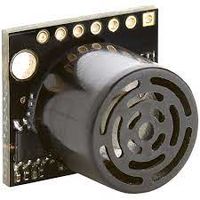
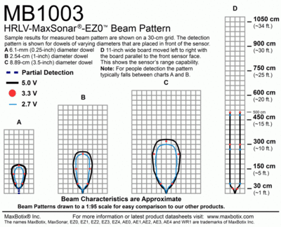
Roadrunner uses three HRLV-MAXSonar-EZ0 MB1003[9] as its eyes and ears on the front. The HRLV-MAXSonar-EZ0 comes in five different models for the ultrasonic sensor. The HRLV-MAXSonar-EZ sensor line is the most cost-effective solution for applications where precision range-finding, low-voltage operation, space-saving, and low-cost are needed. This sensor line features 1mm resolution, target-size and operating-voltage compensation for improved accuracy, superior rejection of outside noise sources, internal speed-of-sound temperature compensation, and optional external speed-of-sound temperature compensation.
These models are the MB1003, MB1013, MB1023, MB1033, and MB1043. The models are based on the beam width of the sensor. It was observed that MB1003 has the optimal beam pattern and was better suited for our objective of object detection. If the beam pattern is too wide given the, there is a greater chance of cross talk between sensors. If the beam pattern is too narrow, there may be blind spots which must be accounted for. Thus, three HRLV-MAXSonar-EZ0 MB1003 sensors were used and the possible unavoidable cross talk is contained by the optimal positioning and software configuration.
Sensor Mounts and Placement
It is decided to place the ultrasonic sensors on 3d- printed mounts and a custom setup to reduce the cross talk and also position them to capture the most field of view and possibly avoid any blind spots for the car movement.
Sensor Readings Extraction
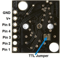
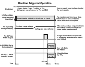
To extract range readings from the MB1003, the "AN" pin which represents analog output was utilized. A range reading is commanded by triggering the "RX" pin high for 20us or more. From the details of the sensor datasheet it is observed that the output analog voltage is based on a scaling factor of (Vcc/512) per inch. As in our setup, all three of the sensors were powered from a 5v supply line, thus a 5v VCC was supplied to each sensor. According to the HRLV-MaxSonar-EZ datasheet, with 5v source, the analog output was expected to be roughly 4.88mV per 5mm. However, when initially testing the output range readings, the output was inaccurate. We were thankful for the past students experiences to notice that the ADC channels for the SJTWO are configured at start-up to have an internal pull up resistor. Disabling this pull up resistor will be discussed more in Software Design and this made the range readings more accurate. The readings were tested by having multiple objects placed in front of each sensor and measuring the distance of the object to the sensors physically. Although the range readings accuracy is improved by the pull-up resistor modification, it was found that the range readings did not necessarily follow the expected 4.88 mV per 5 mm. Hence, we decided to calibrate the sensors to work according to the conversion factor. This value was extracted by placing objects around the sensors and checking if the analog output to centimeter conversion matched to the actual measured distance.
SJ2 Board Pin Connections with Ultrasonic sensors
Sensors are interfaced with combination of GPIO, ADC Pins on SJTwo board. Below is the descriptive pin layout:
| Sr. No. | SJTwo board Pin | Maxbotix sensor Pin | Function |
|---|---|---|---|
| 1 | ADC2 - P0.25 | AN (Middle sensor) | ADC Input (sensor output) from front sensor |
| 2 | ADC4 - P1.30 | AN (Left Sensor) | ADC input from left sensor |
| 3 | ADC5 - P1.31 | AN (Right Sensor) | ADC input from right sensor |
| 4 | GPIO - P0.6 | RX (Middle Sensor) | Trigger Input for left sensor |
| 5 | GPIO - P0.7 | RX (Left Sensor) | Trigger Input for front sensor |
| 6 | GPIO - P0.8 | RX (Right Sensor) | Trigger Input for right sensor |
Software Design
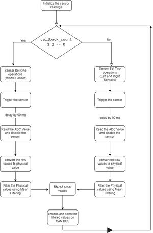
The software is designed as briefed below:
- Initialize all the sensors once the car is powered on.
- Once Initialized, using the callback counter from the 10Hz function, trigger the sensors as two sets, the middle one alone forming set one and the two side sensors, the left and right sensors being set two. (It is also observed and implemented that once we trigger the Maxbotix sensor and we should wait for approximately 90 ms before reading from it to have a good capture of the distance/obstacle).
- The raw ADC values are captured from that group of sensors.
- The sensors are disabled as groups and the other group is triggered and follows the same set of operations and this pattern cycles.
- The raw ADC values are captured and converted into physical distance values in cm using a conversion factor based on the supplying voltage and number of ADC bits.
- The converted values are added to a buffer to calculate the mean from the latest 3 samples (The choice of 3 samples is a compromise we arrived at due to sensor sensitivity, timing and accuracy)and consider it as the current captured value from the sensor.
- This filtered value is then encoded and transmitted on to the CAN bus, where the driver node considers the distance value to operate in different scenarios.
Technical Challenges
- The interference between the ultrasonic sensors is an unavoidable challenge for us as we used the same model of the ultrasonic sensor, hence the same frequency of operation for all the three ultrasonic sensors.
- The solution was to group the sensors and trigger them alternatively with the aim to reduce the beam pattern of the left and right sensors from interfering with each other and especially with the middle sensor.
- Part of the solution was also to physically mount them at an angle to avoid the interference to an extent and also not to create any blind spots in the zone of operations.
- Initially the 3.3v power supply to the Ultrasonic sensor created inconsistent readings from time to time, and later we decided to switch it to 5v operating voltage which made the sensor readings more stable and reliable.
- The compromise of just using 3 samples in the mean filtering is a limitation for our sensor operations, this is due to the fact that with a higher number of samples, we might miss any samples and output time delayed samples on the CAN BUS which will have unpredictable and unwanted consequences.
- These sensors had a limited 10Hz reading update, which is too slow to use as a reliable obstacle detector while the car is moving. We highly recommend you find a different sensor that has AT LEAST a 20Hz update rate.
- The manufacturer recommended reading the sensor data using ADC. This is not reliable, especially if the sensors are connected to the same power supply as the rest of the car. We highly recommend you use some sort of serial communication protocol for the sensors.
- Please use the sensors that the Testla team used from this same semester. If we had another chance, we would use those instead.
- Also check out Testla's 3D-printed adjustable sensor mounts. You should do the same thing!
Motor Controller
Motor Controller Master Branch
Hardware Design
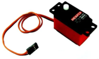
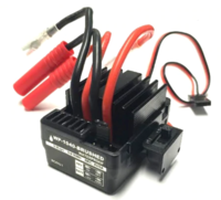
Redcat ESC and Servo from the RC Car
The Motor Controller Node Motor and Servo control were heavily dependent on the hardware and communication protocols that came with our RC car. Originally, when we got the RC car, for some reason we expected some support from the vendor on offering some form of datasheet that gave us an idea on the PWM signal range controlled by the ESC and Servo. However, unsurprisingly, that wasn't the case.
The following parts were installed on the Redcat BLACKOUT-SC-RED RC Car:
| Type | Vendor | Model Number | Communication Protocol |
|---|---|---|---|
| Motor ESC | Redcat | WP-1040-BRUSHED | PWM |
| Servo | Redcat | HX-3CP | PWM |
Since there were no datasheets provided by Redcat for both the Servo and Motor ESC, we used the connections on the receiver to determine which wire corresponded to Signal, VCC, and GND connections. To drive both Servo and Motor, the ground pins for Servo, Motor and SJ2 must be connected together.
| Part Name | Signal Name | Part Pin # | Color | SJ2 Pin # |
|---|---|---|---|---|
| Servo | PWM | 1 | Orange | P2.0 |
| Servo | VCC | 2 | Brown | 3.3V |
| Servo | GND | 3 | Black | GND |
| Motor ESC | PWM | 1 | White | P2.1 |
| Motor ESC | VCC | 2 | Red | 3.3V |
| Motor ESC | GND | 3 | Black | GND |
After we determined the pinouts above, we went to the IEEE lab and used an oscilloscope connected in parallel with receiver to monitor the signals returned from the receiver when applying various inputs through the remote that control the Motor ESC and the Servo. The following tables are the PWM min max values for the servo and Motor ESC observed from the oscilloscope respectively.
| Servo Angle (deg) | PWM Duty Cycle % | PWM Frequency (Hz) |
|---|---|---|
| -45.0 (left) | 11.67 | 60.24 |
| 0.0 | 8.65 | 60.24 |
| +45.0 (right) | 6.024 | 60.24 |
| Motor Speed (kph) | PWM Duty Cycle % | PWM Frequency (Hz) |
|---|---|---|
| -40.2336 (reverse) | 6.205 | 60.24 |
| 0.0 (stopped) | 9.21 | 60.24 |
| +40.2336 (forward) | 12.048 | 60.24 |
RPM Sensor
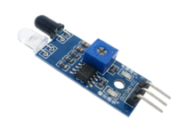
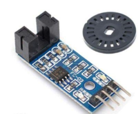
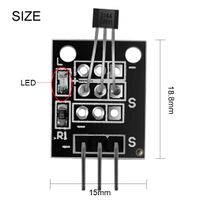
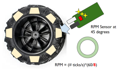
Throughout the course of the project we tried three different RPM sensors: IR[10], Hall[11], and Optocoupler[12]
In order not to tamper with the RC car in any way, we opted to choose the RPM sensors which could be mounted near the backside of the wheel (IR/Hall) instead of the Axel (Optocoupler). The RPM sensor was mounted near the axel connecting the rear-right wheel of the car at 45 degrees, against several equally spaced adhesive strips of a certain color (IR) or attached magnets (Hall). Originally we used the IR sensor as we already had that part on hand and realized that indoors it worked fine but outdoors in the sunlight, it couldn't be used successfully. In the 2-3 weeks of the project we ended up switching to the Hall Sensor which worked in all lighting scenarios. In order to improve accuracy, we used 9 adhesive strips with the IR sensor, but ended up having to reduce the strips to 3 with the attached magnet due to the strength of the magnets preventing strips being attached too close to each other.
Software Design
Redcat ESC and Servo
Originally, for the first few weeks of the project, we did a lot of trial and error with the RPM sensor and RPM->KPH conversion function to collect PWM of different speeds and use Google Sheets trendline curves to figure out the function to convert kph->pwm and angle->pwm which worked for RC car when running on the ground.
Original Code
Originally, the PWM was calculated with inputs of KPH (Motor) and Angle (Servo). The Motor function used a cubed trendline function (due to non-linearity of motor PWM) while the Servo function used a linear curve.
redcat_esc.c
   static float servo_angle_to_pwm(float angle) {
       float slope = -0.04122222222; // Switching sign, switches RIGHT= -45 to RIGHT= +45
       float intercept = 8.645733333;
       float pwm_for_angle = (slope * angle) + intercept;
       return pwm_for_angle;
   }
   float motor_speed_to_pwm(float kph) {
       float pwm_for_speed = 0.0;
       if (kph == 0.0) {
           pwm_for_speed = motor_stopped_pwm_duty_cycle;
       } else {
           float adjusted_kph = kph;
           pwm_for_speed = 9.08 + (0.059 * adjusted_kph) + (0.0000222 * adjusted_kph * adjusted_kph) +
                           (0.0000084 * adjusted_kph * adjusted_kph * adjusted_kph);
           const float lowest_achievable_speed_pwm = 9.892;
           if ((kph > 0) && (pwm_for_speed < motor_minimum_forward_duty_cycle)) {
               pwm_for_speed = motor_minimum_forward_duty_cycle;
           } else if ((kph < 0) && (pwm_for_speed > motor_maximum_reverse_duty_cycle)) {
               pwm_for_speed = motor_maximum_reverse_duty_cycle;
           }
       }
       return pwm_for_speed;
   }
motor_and_servo.c
   bool receive_motor_servo_can_dbc_message__10Hz(void) {
       bool received_motor_servo_message_successfully = false;
       if (dbc_receive_can_message(&can_msg_received_motor_cmd)) {
           redcat_esc_pwm_set_servo_angle(can_msg_received_motor_cmd.MOTOR_steer_degrees);
           redcat_esc_config current_motor_servo_cfg = helper__get_current_esc_config();
           float current_kph = current_motor_servo_cfg.motor_speed_kph;
           float new_kph = can_msg_received_motor_cmd.MOTOR_speed_kph;
           if (current_kph != new_kph) {
               redcat_esc_pwm_set_motor_speed(can_msg_received_motor_cmd.MOTOR_speed_kph);
           }
           received_motor_servo_message_successfully = true;
       }
       return received_motor_servo_message_successfully;
   }
Refactored Code
Towards the end of the project, we simplified the motor node completely and motor_speed_to_pwm() function was removed. Instead, the motor speeds were changed to hard-set PWM constant values with the RPM sensor being entirely required in order to even drive the motor (no separate PID function -- it was combined together with the Motor Speed PWM set function):
motor_and_servo.c
   // Motor PWM
   static const float pwm_motor_drive_backwards_lower_limit = 7.0f;
   static const float pwm_motor_drive_backwards = 8.2;
   static const float pwm_motor_stop = 9.2f;
   static const float pwm_motor_drive_forwards = 9.7f;
   static const float pwm_motor_drive_forwards_upper_limit = 11.0f;
   static float compute_steer_pwm(int16_t command_steer_direction) {
       float pwm_steer = 0.0f;
       switch (command_steer_direction) {
           case STEER_MAX_LEFT:
               pwm_steer = pwm_steer_max_left;
               break;
           case STEER_SLIGHT_LEFT:
               pwm_steer = pwm_steer_slight_left;
               break;
           case STEER_SLIGHT_RIGHT:
               pwm_steer = pwm_steer_slight_right;
               break;
           case STEER_MAX_RIGHT:
               pwm_steer = pwm_steer_max_right;
               break;
           default:
               pwm_steer = pwm_steer_straight;
       }
       return pwm_steer;
   }
   static void process_normal_drive_operation(float *motor_pwm, float *steer_pwm, float *target_kph, float *actual_kph) {
       // Debug messages for drive command
       current_motor_status.actual_steer_degrees = last_received_motor_cmd.MOTOR_steer_direction;
       current_motor_control_debug.target_steer_direction = last_received_motor_cmd.MOTOR_steer_direction;
       current_motor_control_debug.is_override_enabled = false;
       // Handle the different drive modes
       MOTOR_drive_mode_e drive_mode = last_received_motor_cmd.MOTOR_drive_mode;
       current_motor_status.actual_drive_mode = drive_mode;
       if (NEUTRAL == drive_mode) {
           *motor_pwm = pwm_motor_stop;
           *steer_pwm = compute_steer_pwm(last_received_motor_cmd.MOTOR_steer_direction);
           current_motor_control_debug.target_speed_kph = 0.0f;
       } else {
           /****************** Find target speed ***************************/
           *target_kph = last_received_motor_cmd.MOTOR_speed_kph;
           current_motor_control_debug.target_speed_kph = last_received_motor_cmd.MOTOR_speed_kph;
           /****************** Find current actual speed *******************/
           // Calculate RPM values from sensor
           uint32_t encoder_ticks = rpm_sensor__get_tick_count();
           uint32_t rpm = rpm_sensor__calculate_rpm_10Hz();
           *actual_kph = rpm_sensor__calculate_kph_from_rpm(rpm);
           // Calculate Motor PWM output values
           if (DRIVE_FORWARDS == drive_mode) {
               *motor_pwm =
                   compute_motor_pwm(*target_kph, *actual_kph, pwm_motor_drive_forwards, pwm_motor_drive_forwards_upper_limit);
           } else {
               *actual_kph *= -1;
               *motor_pwm =
                   compute_motor_pwm(*target_kph, *actual_kph, pwm_motor_drive_backwards_lower_limit, pwm_motor_drive_backwards);
           }
           // Calculate steering PWM output values
           *steer_pwm = compute_steer_pwm(last_received_motor_cmd.MOTOR_steer_direction);
           // Debug messages for RPM
           current_motor_rpm_debug.total_encod er_tick_count = encoder_ticks;
           current_motor_rpm_debug.computed_rpm = rpm;
           current_motor_rpm_debug.computed_kph = *actual_kph;
           current_motor_status.actual_speed_kph = *actual_kph;
       }
   }
RPM Sensor
Every RPM sensor triggers a digital output = 1 whenever an obstacle is present in front of the sensors. For the IR sensor, when a different colored object other than black is present, output = 1. In contrast, the Hall sensor (which we ended up using for the final demo) uses a magnet positioned perpendicular to the sensor. the sensor output = 0 every other time.
A tick is therefore measured when the output changes from digital output = 0 to 1. The fastest measurement for each tick is 1ms (1000Hz) function. The ticks are continuously incremented every 1ms until rpm_sensor__calculate_rpm_10Hz() function is called which essentially multiplies the result in 100ms by 10 for the RPS("Rate Per Second") and then by 60 for the resultant RPM. As mentioned earlier, more ticks per rotation increases the accuracy of the RPM sensor. Since the Hall Sensor had 3 ticks per rotation, the final RPM sensor value is the total ticks in 10Hz * 600 divided by 3.
rpm_sensor.c
   static bool prev_value = false;
   static bool cur_value = false;
   static const uint32_t SECONDS_RPM = 60;
   static const uint32_t CALC_FREQ_HZ = 5;
   static const uint32_t ENCODER_TICKS_PER_REVOLUTION = 3;
   void rpm_sensor__sample_periodic(void) {
       cur_value = gpio__get(sensor_pin);
       if (cur_value != prev_value) {
           total_encoder_count++;
       }
       prev_value = cur_value;
   }
   uint32_t rpm_sensor__calculate_rpm_10Hz(void) {
       last_period_encoder_count = total_encoder_count - last_period_encoder_count;
       uint32_t rpm = (SECONDS_RPM * last_period_encoder_count * CALC_FREQ_HZ) / ENCODER_TICKS_PER_REVOLUTION;
       last_period_encoder_count = total_encoder_count;
       return rpm;
   }
Technical Challenges
- The RPM sensor that we used does not work work in direct sunlight. It is an IR sensor, and it becomes useless if exposed to the Sun's IR rays. Please don't use an external IR sensor for your RPM sensing. Buy the Traxxas car that comes with a special RPM sensor that gets installed in the motor housing. This is much more reliable, and it does not get exposed to outdoor lighting.
- The initial motor code tried to use hard-coded PWM values for controlling the motor. This is not reliable, especially on the cheaper RedCat car, whose ESC is quite terrible. Please buy the Traxxas car to have a more stable ESC (but watch out for the more complicated startup sequence).
- Use a simple Proportional control (PID) algorithm to control your motor, using the RPM sensor readings as the feedback signal. You might even be able to get away with just P-only control. Watch this video to learn everything you need about implementing this: https://www.youtube.com/watch?v=JEpWlTl95Tw&t=2s
Geographical Controller
Geological Controller Master Branch
Hardware Design
| SJTwo board Pin | Device | Bus-Type | Pin-Function |
|---|---|---|---|
| P4.28 | GPS | UART | TX |
| P4.29 | GPS | UART | RX |
| P0.10 | Compass | I2C | SDA |
| P0.11 | Compass | I2C | SCL |
| P0.0 | CAN Tran | CAN | RD |
| P0.1 | CAN Tran | CAN | TD |
Software Design
GPS
Since we have configured the GPS module to return at 2Hz and only returns GPGGA strings, and we have a coin cell battery for it to hold all of its configuration, we decided that there is no need to re-configure it every time when it starts up. However, the configuration functions gpgga_only and twoHz_only are in the repo for reference.
The main GPS periodic function is gps__run_once, which calls the two sub GPS functions gps__transfer_data_from_uart_driver_to_line_buffer and gps__parse_coordinates_from_line. gps__transfer_data_from_uart_driver_to_line_buffer reads from the UART buffer and adds it to our line buffer data structure. gps__parse_coordinates_from_line removes a line from the line buffer and parses it into latitude and longitude.
The second, third, and fourth periodic function are gps_processor__calculate_distance_to_destination, gps_processor__calculate_distance_to_waypoint, and gps_processor__calculate_bearing_to_destination.
gps_processor__calculate_distance_to_destination calculates the distance between the current position and the destination with the Haversine formula. This function is used for checking if we are close to the destination.
gps_processor__calculate_distance_to_waypoint calculates the distance between the current position and a waypoint position with the same formula. This function is used for calculating the closest waypoint.
After that, we will use gps_processor__calculate_bearing_to_destination to calculate the bearing angle (The angle relative to our car’s position).
The reason why there are two functions for calculating distance is because this allows us to have destination and waypoints to be different types of input.
Distance
 const float earth_radius = 6371000; // 6371km
                                     // Convert current coordinates into radians
 float current_latitude = geo_position.GEO_CURRENT_POSITION_latitude;
 float current_longitutde = geo_position.GEO_CURRENT_POSITION_longitude;
 // Convert destination coords into radians
 float destination_latitude = gps_destination.GPS_DESTINATION_latitude;
 float destination_longitude = gps_destination.GPS_DESTINATION_longitude;
 float theta1 = destination_latitude * PI / 180; // in radian (current_loc or dest_loc as theta1 doesn't matter)
 float theta2 = current_latitude * PI / 180;     // in radian
 float delta_theta = (destination_latitude - current_latitude) * PI / 180;
 float delta_lambda = (destination_longitude - current_longitutde) * PI / 180; // in radian
 float a = powf(sinf(delta_theta / 2), 2) + cosf(theta1) * cosf(theta2) * powf(sinf(delta_lambda / 2), 2);
 float c = 2 * atan2f(sqrtf(a), sqrtf(1 - a));
 float distance = earth_radius * c; // in meters
 return distance;
Bearing
 // Convert current coordinates into radians
 float current_latitude = geo_position.GEO_CURRENT_POSITION_latitude * PI / 180;
 float current_longitude = geo_position.GEO_CURRENT_POSITION_longitude * PI / 180;
 // Convert destination coords into radians
 float destination_latitude = gps_destination.GPS_DESTINATION_latitude * PI / 180;
 float destination_longitude = gps_destination.GPS_DESTINATION_longitude * PI / 180;
 float y = sin(destination_longitude - current_longitude) * cos(destination_latitude);
 float x = cos(current_latitude) * sin(destination_latitude) -
           sin(current_latitude) * cos(destination_latitude) * cos(destination_longitude - current_longitude);
 float theta = atan2(y, x);
 // Convert theta to degrees
 float bearing = fmodf(((theta * 180.0f / PI) + 360.0f), 360);
 return round(bearing);
Compass
The compass we use has an embedded processor that filters and tile compensates the raw data from the magnetometer, so we only need to read the correct slave data registers and shift them to create a 16-bit unsigned integer, then dividing it by 10 since the range is from 0.0 to 359.9. Since the filtering and calibrations are already done by the hardware module, the code doesn’t need further filtering or calibration to work properly.
Waypoint
Instead of having a list of hardcoded waypoint positions, we decided to have our smart phone app send up to ten waypoints. From the list of waypoints, geo_processor calls the waypoint__get_coordinates function to get the closest waypoint coordinates. Within that, the find_closest_waypoint function is called and returns an index between 0-9, and -1 if going straight to the destination is the closest path.
If we arrive at the waypoint, it is removed from the list, and we will fetch the next closest waypoint.
waypoint__get_coordinates is called continuously so that if the car steers away from the intended path to avoid obstacles, it can find a closer waypoint, instead of going to the original waypoint.
Technical Challenges
- We first bought a cheaper compass sensor since the good one was out of stock (semiconductor shortage T.T). This led to a lot of trouble trying to do the calibration and motion compensation (the compass will be moving and accelerating with the car as it drives). You NEED to find a self-calibrated/compensated compass like the CMPS-12 or CMPS-14. Order it as soon as you read this. You really need to have as many electrical components as possible that "just work" because otherwise you won't have any time to write quality software or unit tests.
- At the beginning, we were having issues configuring the GPS to only send GPGGA strings. We knew that the GPS module and the configuration message worked because we tested it in telemetry.
- We moved the sending of the configuration messages from initialization to a periodic callback that runs only once at the first 20 seconds. This solved our issue. We presume that it is because initialization takes place during RTOS startup, and the UART may not have fully initialized at that point.
- The GPS peripheral takes time to obtain a lock, and it can get confusing why it is not working all the time. You have to use a GPS that has a coin-cell battery component to maintain the lock data between power cycles. Having a coin cell battery also helped us to not need to re-configure the GPS every time when it loses power.
- The waypoints algorithm is hard to test if you are still stuck on getting the rest of the car working. We highly recommend you test the GEO node (compass and GPS integration) separately from the car. You can find a table with wheels in the IEEE room or most lecture rooms. Put your peripherals and boards on it, hook up BusMaster, and "drive" the table around as your testbench.
Driver and LCD Module
Hardware Design
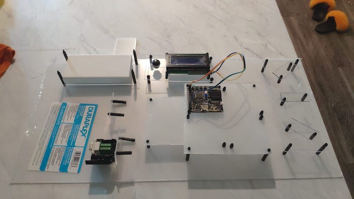
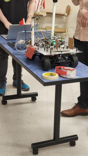
Your most important hardware is a moveable table you can put your car on and "drive" around while you verify the motor commands and algorithm decisions on BusMaster! The LCD screen can also be helpful.
LCD Display
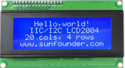
Originally we had planned for the Driver Node to interface with both the LCD Display and the Adafruit 16-count RING LED. However, due to special programming techniques giving us problems (assembly ASM NOP not working correctly), we had to opt out of using it. Instead, we entirely used the LCD Display menu for the Compass readings to determine the direction of the compass and heading mentally.
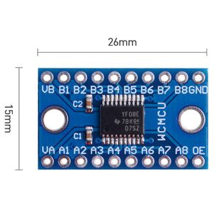
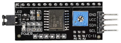
The LCD Display we used was a 20x4 HD44780[13] LCD Controller which uses a combination of GPIO pin inputs to control the behavior of characters displayed on the screen. The product we bought actually interfaces with this LCD controller using I2C through a PCA8574[14] chip called a GPIO expander, which basically takes an I2C data transaction and translates that into either a GPIO set or read. For the general purpose of using the expander to program the LCD display, we only really focused on the GPIO write functionality of that controller. Due to difficulty finding a 3.3V 20x4 I2C LCD Display, we ended up purchasing a 5.0V display and a TXS0108E[15] GPIO Bi-directional Logic Shifter chip to convert I2C from SJ2 of 3.3V up to 5.0V to the LCD GPIO expander.
| SJTwo board Pin | Device | Bus-Type | Pin-Function |
|---|---|---|---|
| P0.10 | LCD Display | I2C | SDA |
| P0.11 | LCD Display | I2C | SCL |
| 3.3V | LCD Display | I2C | Logic Shifter VCC |
| GND | LCD Display | I2C | Logic Shifter GND |
Sparkfun has an excellent guide[16] on how to use the Logic Shifter. It should be noted here though that both GND pins from source and destination must be connected together. In this case, the LCD display GND must be connected to the GND pin of the Logic Shifter which in turn is connected to the GND pin of the SJ2 board. The following is the pinout on the Logic Shifter we used to driving the LCD display.
| Logic Shifter Pin | Destination | Pin | Protocol |
|---|---|---|---|
| VA | SJ2 | 3.3V | |
| VB | LCD I2C | VCC | |
| OE | SJ2 | 3.3V | |
| GND | SJ2, LCD I2C | GND | |
| A1 | SJ2 | P0.10 | I2C |
| A2 | SJ2 | P0.11 | I2C |
| B1 | LCD I2C | SDA | I2C |
| B2 | LCD I2C | SCL | I2C |
Software Design
LCD Display
The first step to make the LCD display work was testing it with Arduino. The library we used was the LiquidCrystal_I2C[17] Git library. The menu was first tested and made on Arduino and then later ported to SJ2, with some basic changes. This Arduino library already included to I2C GPIO expander logic inside the library, but on SJ2 we decided to modularize it and separate the LCD driver logic by making two libraries: I2C LCD and GPIO expander. The I2C LCD library uses the GPIO expander library to perform the I2C communication while the bits that are passed to the GPIO expander library are generated in the LCD library itself.
The GPIO expander does not have a register address for it's send byte function. Instead we replace the register address with the data field for a total of two data fields. Unlike the address on the Arduino showing up as 0x27, on SJ2 with 3.3V it is 0x4E instead.
GPIO Expander sendbye() function:
   // The following defines are for supported I2S addresses.
   #define GPIO_EXPANDER_PCF8574_DEFAULT_ADDRESS = 0x40;
   #define GPIO_EXPANDER_PCA8574_DEFAULT_ADDRESS = 0x4E;
   static uint8_t multiple_gpio_expanders[3] = {0x40, 0x42, 0x44};
   static i2c_e expanders_i2c_buses[3] = {I2C__2, I2C__2, I2C__2};
   void gpio_expander_i2c__sendbyte(uint8_t byte, uint8_t expander_number) {
       uint8_t pins_to_set = byte;
       if (bits_need_inverting) {
           pins_to_set = gpio_expander_i2c__invert_bits_for_matching_bit_state(byte);
       }
       uint8_t write_address = gpio_expander_i2c__i2c_slave_address(false, expander_number);
       if (bus_was_initialized) {
           bool write_success =
               i2c__write_single(expanders_i2c_buses[expander_number], write_address, pins_to_set, pins_to_set);
           if (!write_success) {
               printf("I2C Write failed!\n");
           }
       } else {
           printf("I2S initialization was not called correctly!\n");
       }
   }
High-level LCD display functions:
   #define LCD_CLEARDISPLAY 0x01
   #define LCD_RETURNHOME 0x02
   #define LCD_ENTRYMODESET 0x04
   #define LCD_DISPLAYCONTROL 0x08
   #define LCD_CURSORSHIFT 0x10
   #define LCD_FUNCTIONSET 0x20
   #define LCD_SETDDRAMADDR 0x80
   #define LCD_ENTRYRIGHT 0x00
   #define LCD_ENTRYLEFT 0x02
   #define LCD_ENTRYSHIFTINCREMENT 0x01
   #define LCD_ENTRYSHIFTDECREMENT 0x00
   #define LCD_DISPLAYON 0x04
   #define LCD_DISPLAYOFF 0x00
   #define LCD_CURSORON 0x02
   #define LCD_CURSOROFF 0x00
   #define LCD_DISPLAYMOVE 0x08
   #define LCD_8BITMODE 0x10
   #define LCD_2LINE 0x08
   #define LCD_5x10DOTS 0x04
   #define LCD_5x8DOTS 0x00
   #define LCD_BACKLIGHT 0x08
   #define LCD_EN 0x04
   #define LCD_RW 0x02
   #define LCD_RS 0x01
   void i2c_lcd_display__begin(uint8_t cols, uint8_t lines, uint8_t dotsize) {
       if (lines > 1) {
           display_function |= LCD_2LINE;
       }
       num_lines = lines;
       if ((dotsize != 0) && (lines == 1)) {
           display_function |= LCD_5x10DOTS;
       }
       delay__ms(50);
       i2c_lcd_display__sendRaw(backlight_value);
       delay__ms(1000);
       i2c_lcd_display__write4bits(0x03 << 4);
       delay__us(4500);
       i2c_lcd_display__write4bits(0x03 << 4);
       delay__us(4500);
       i2c_lcd_display__write4bits(0x03 << 4);
       delay__us(150);
       i2c_lcd_display__write4bits(0x02 << 4);
       i2c_lcd_display__sendCommand(LCD_FUNCTIONSET | display_function);
       display_control = LCD_DISPLAYON | LCD_CURSOROFF | LCD_BLINKOFF;
       i2c_lcd_display__display();
       i2c_lcd_display__clear();
       display_mode = LCD_ENTRYLEFT | LCD_ENTRYSHIFTDECREMENT;
       i2c_lcd_display__sendCommand(LCD_ENTRYMODESET | display_mode);
       i2c_lcd_display__home();
   }
   void i2c_lcd_display__clear() {
       i2c_lcd_display__sendCommand(LCD_CLEARDISPLAY);
       delay__us(2000);
   }
   void i2c_lcd_display__setCursor(uint8_t col, uint8_t row) {
       int row_offsets[] = {0x00, 0x40, 0x14, 0x54};
       if (row > num_lines) {
           row = num_lines - 1;
       }
       i2c_lcd_display__sendCommand(LCD_SETDDRAMADDR | (col + row_offsets[row]));
   }
   static void i2c_lcd_display__send(uint8_t value, uint8_t mode) {
       uint8_t msb_first_four_bits = value & 0xF0;
       uint8_t msb_last_four_bits = (value << 4) & 0xF0;
       i2c_lcd_display__write4bits(msb_first_four_bits | mode);
       i2c_lcd_display__write4bits(msb_last_four_bits | mode);
   }
   static void i2c_lcd_display__write4bits(uint8_t value) {
       i2c_lcd_display__sendRaw(value);
       i2c_lcd_display__pulse_enable(value);
   }
   static void i2c_lcd_display__pulse_enable(uint8_t data) {
       i2c_lcd_display__sendRaw(data | LCD_EN);
       delay__us(1);
       i2c_lcd_display__sendRaw(data & ~LCD_EN);
       delay__us(50);
   }
   static void i2c_lcd_display__sendRaw(uint8_t data) {
       gpio_expander_i2c__sendbyte(data | backlight_value, 0);
   }
   static void i2c_lcd_display__write(uint8_t value) {
       i2c_lcd_display__send(value, LCD_RS);
   }
   void i2c_lcd_display__print(const char *sentence) {
       i2c_lcd_display__print_sentence(sentence);
   }
   static void i2c_lcd_display__print_sentence(const char *buffer) {
       size_t length_of_buffer = strlen(buffer);
       for (uint8_t char_idx = 0; char_idx < length_of_buffer; char_idx++) {
           i2c_lcd_display__write(buffer[char_idx]);
       }
   }
RC Car LCD Menus:
   static uint8_t car_lcd_cycling_menu_counter = 0;
   static bool car_lcd_driver_node_drive_started = false;
   static bool car_lcd_driver_node_headlights_on = false;
   static bool car_lcd_driver_node_destination_reached = false;
   static uint32_t car_lcd_can_counts[2] = {0, 0};
   static dbc_SENSOR_SONARS_s car_lcd_sensor_node_dbc_rx;
   static dbc_DEBUG_MOTOR_CONTROL_s car_lcd_motor_node_motor_servo_dbc_rx;
   static dbc_DEBUG_MOTOR_RPM_s car_lcd_motor_node_rpm_dbc_rx;
   static dbc_GEO_CURRENT_POSITION_s car_lcd_geo_node_gps_dbc_rx;
   static dbc_GEO_STATUS_s car_lcd_geo_node_compass_dbc_rx;
   static dbc_GPS_DESTINATION_s car_lcd_geo_node_bt_dest_dbc_rx;
   bool car_lcd__menu_boot__1Hz(uint32_t callback_count) {
       i2c_lcd_display__clear();
       i2c_lcd_display__backlight();
       i2c_lcd_display__setCursor(0, 0);
       i2c_lcd_display__print("+------------------+");
       i2c_lcd_display__setCursor(0, 1);
       i2c_lcd_display__print("Road Runner");
       i2c_lcd_display__setCursor(0, 2);
       i2c_lcd_display__print("Boot Sequence...");
       i2c_lcd_display__setCursor(0, 3);
       i2c_lcd_display__print("+------------------+");
       if ((callback_count % 6) == 0) {
           return true;
       } else {
           return false;
       }
   }
   void car_lcd__menu_driver_node__1Hz(void) {
       char text_drive_started[4] = {0};
       char text_headlights[4] = {0};
       char text_can_rx_cnt[6] = {0};
       char text_can_tx_cnt[6] = {0};
       char text_dest_reached[4] = {0};
       if (car_lcd_driver_node_drive_started) {
           sprintf(text_drive_started, "Yes");
       } else {
           sprintf(text_drive_started, "No");
       }
       if (car_lcd_driver_node_headlights_on) {
           sprintf(text_headlights, "Yes");
       } else {
           sprintf(text_headlights, "No");
       }
       if (car_lcd_driver_node_destination_reached) {
           sprintf(text_dest_reached, "Yes");
       } else {
           sprintf(text_dest_reached, "No");
       }
       sprintf(text_can_rx_cnt, "%d", (uint16_t)car_lcd_can_counts[0]);
       sprintf(text_can_tx_cnt, "%d", (uint16_t)car_lcd_can_counts[1]);
       i2c_lcd_display__backlight();
       i2c_lcd_display__setCursor(0, 0);
       i2c_lcd_display__print("Driver Node");
       i2c_lcd_display__setCursor(0, 1);
       char pushbutton_start_and_headlights[20];
       sprintf(pushbutton_start_and_headlights, "D Start:%s,H:%s", text_drive_started, text_headlights);
       i2c_lcd_display__print(pushbutton_start_and_headlights);
       i2c_lcd_display__setCursor(0, 2);
       char can_rx_and_tx[20];
       sprintf(can_rx_and_tx, "RX: %s,TX: %s", text_can_rx_cnt, text_can_tx_cnt);
       i2c_lcd_display__print(can_rx_and_tx);
       i2c_lcd_display__setCursor(0, 3);
       char destination_reached[20];
       sprintf(destination_reached, "Dest reached:%s", text_dest_reached);
       i2c_lcd_display__print(destination_reached);
   }
   void car_lcd__menu_sensor_node__1Hz(void) {
       char text_sensor_left[6] = {0};
       char text_sensor_front[6] = {0};
       char text_sensor_right[6] = {0};
       char text_sensor_back[6] = {0};
       sprintf(text_sensor_left, "%d", car_lcd_sensor_node_dbc_rx.SENSOR_SONARS_left);
       sprintf(text_sensor_front, "%d", car_lcd_sensor_node_dbc_rx.SENSOR_SONARS_middle);
       sprintf(text_sensor_right, "%d", car_lcd_sensor_node_dbc_rx.SENSOR_SONARS_right);
       sprintf(text_sensor_back, "%d", car_lcd_sensor_node_dbc_rx.SENSOR_SONARS_back);
       i2c_lcd_display__backlight();
       i2c_lcd_display__setCursor(0, 0);
       i2c_lcd_display__print("Sensor Node");
       i2c_lcd_display__setCursor(0, 1);
       char left_and_right_sensor[20];
       sprintf(left_and_right_sensor, "L: %s, R: %s", text_sensor_left, text_sensor_right);
       i2c_lcd_display__print(left_and_right_sensor);
       i2c_lcd_display__setCursor(0, 2);
       char front_sensor[20];
       sprintf(front_sensor, "Front:%s", text_sensor_front);
       i2c_lcd_display__print(front_sensor);
       i2c_lcd_display__setCursor(0, 3);
       char rear_sensor[20];
       sprintf(rear_sensor, "Rear:%s", text_sensor_back);
       i2c_lcd_display__print(rear_sensor);
   }
   void car_lcd__menu_motor_node__1Hz(void) {
       char text_servo_angle[6] = {0};
       char text_servo_pwm[6] = {0};
       char text_motor_speed[6] = {0};
       char text_motor_pwm[6] = {0};
       char text_rpm_sensor[7] = {0};
       float angle = 0.0f;
       if (car_lcd_motor_node_motor_servo_dbc_rx.target_steer_direction == -1) {
           angle = -20.72f;
       } else if (car_lcd_motor_node_motor_servo_dbc_rx.target_steer_direction == -2) {
           angle = 45.0f;
       } else if (car_lcd_motor_node_motor_servo_dbc_rx.target_steer_direction == 1) {
           angle = 21.73f;
       } else if (car_lcd_motor_node_motor_servo_dbc_rx.target_steer_direction == 2) {
           angle = 45.0f;
       }
       sprintf(text_servo_angle, "%0.2f", angle);
       sprintf(text_servo_pwm, "%0.2f", car_lcd_motor_node_motor_servo_dbc_rx.current_raw_servo_pwm);
       sprintf(text_motor_speed, "%0.2f", car_lcd_motor_node_motor_servo_dbc_rx.target_speed_kph);
       sprintf(text_motor_pwm, "%0.2f", car_lcd_motor_node_motor_servo_dbc_rx.current_raw_motor_pwm);
       sprintf(text_rpm_sensor, "%d", car_lcd_motor_node_rpm_dbc_rx.computed_rpm);
       i2c_lcd_display__backlight();
       i2c_lcd_display__setCursor(0, 0);
       i2c_lcd_display__print("Motor Node");
       i2c_lcd_display__setCursor(0, 1);
       char servo_angle[20];
       sprintf(servo_angle, "Angle:%s(%s)", text_servo_angle, text_servo_pwm);
       i2c_lcd_display__print(servo_angle);
       i2c_lcd_display__setCursor(0, 2);
       char motor_speed[20];
       sprintf(motor_speed, "Motor:%s(%s)", text_motor_speed, text_motor_pwm);
       i2c_lcd_display__print(motor_speed);
       i2c_lcd_display__setCursor(0, 3);
       char rpm_sensor[20];
       sprintf(rpm_sensor, "RPM:%s", text_rpm_sensor);
       i2c_lcd_display__print(rpm_sensor);
   }
   void car_lcd__menu_geo_node_compass__1Hz(void) {
       char text_heading_angle[6] = {0};
       char text_bearing_angle[6] = {0};
       sprintf(text_heading_angle, "%d", car_lcd_geo_node_compass_dbc_rx.GEO_STATUS_COMPASS_HEADING);
       sprintf(text_bearing_angle, "%d", car_lcd_geo_node_compass_dbc_rx.GEO_STATUS_COMPASS_BEARING);
       i2c_lcd_display__setCursor(0, 0);
       i2c_lcd_display__print("Geo Node (Compass)");
       i2c_lcd_display__setCursor(0, 1);
       char compass_heading[20];
       sprintf(compass_heading, "Heading: %s deg", text_heading_angle);
       i2c_lcd_display__print(compass_heading);
       i2c_lcd_display__setCursor(0, 2);
       char compass_bearing[20];
       sprintf(compass_bearing, "Bearing: %s deg", text_bearing_angle);
       i2c_lcd_display__print(compass_bearing);
   }
   void car_lcd__menu_geo_node_gps__1Hz(void) {
       char text_gps_lat[9] = {0};
       char text_gps_long[9] = {0};
       char text_dest_lat[9] = {0};
       char text_dest_long[9] = {0};
       char text_remaining_dist[7] = {0};
       sprintf(text_gps_lat, "%0.3f", car_lcd_geo_node_gps_dbc_rx.GEO_CURRENT_POSITION_latitude);
       sprintf(text_gps_long, "%0.3f", car_lcd_geo_node_gps_dbc_rx.GEO_CURRENT_POSITION_longitude);
       sprintf(text_dest_lat, "%0.3f", car_lcd_geo_node_bt_dest_dbc_rx.GPS_DESTINATION_latitude);
       sprintf(text_dest_long, "%0.3f", car_lcd_geo_node_bt_dest_dbc_rx.GPS_DESTINATION_longitude);
       sprintf(text_remaining_dist, "%d", (uint16_t)car_lcd_geo_node_compass_dbc_rx.GEO_STATUS_DISTANCE_TO_DESTINATION);
       i2c_lcd_display__setCursor(0, 0);
       i2c_lcd_display__print("Geo Node (GPS)");
       i2c_lcd_display__setCursor(0, 1);
       char gps_lat_long[20];
       sprintf(gps_lat_long, "G:%s,%s", text_gps_lat, text_gps_long);
       i2c_lcd_display__print(gps_lat_long);
       i2c_lcd_display__setCursor(0, 2);
       char bt_dest_lat_long[20];
       sprintf(bt_dest_lat_long, "D:%s,%s", text_dest_lat, text_dest_long);
       i2c_lcd_display__print(bt_dest_lat_long);
       i2c_lcd_display__setCursor(0, 3);
       char remaining_distance[20];
       sprintf(remaining_distance, "Distance:%s m", text_remaining_dist);
       i2c_lcd_display__print(remaining_distance);
   }
   void car_lcd__cycling_menu__1Hz(uint32_t callback_count) {
       if ((callback_count % 5) == 0) {
               car_lcd_cycling_menu_counter++;
           if (car_lcd_cycling_menu_counter > 4) {
               car_lcd_cycling_menu_counter = 0;
           }
       }
       i2c_lcd_display__clear();
       switch (car_lcd_cycling_menu_counter) {
       case 0:
           car_lcd__menu_driver_node__1Hz();
           break;
       case 1:
           car_lcd__menu_sensor_node__1Hz();
           break;
       case 2:
           car_lcd__menu_motor_node__1Hz();
           break;
       case 3:
           car_lcd__menu_geo_node_compass__1Hz();
           break;
       case 4:
           car_lcd__menu_geo_node_gps__1Hz();
           break;
       default:
           break;
       }
   }
Driver Logic
High Level Driver Logic:
 if ((gpio__get(EXTERNAL_EMERGENCY_BUTTON))) {
   EMERGENCY_STOP = true;
 }


 if (EMERGENCY_STOP) {
   stop();
 } else if (destination_reached()) {
   destination_reached_processor();
 } else if (has_obstacle()) {
   obstacle_avoidance_processor();
   gpio__reset(board_io__get_led3());
 } else {
   heading_processor();
   gpio__toggle(board_io__get_led3());
 }
And then the Obstacle Avoidance Logic:
 if (is_blocked()) {
   do_reverse_sequence();
 } else if (closest_object_on_left()) {
   turn_right();
 } else if (closest_object_on_right()) {
   turn_left();
 } else {
   stay_straight();
 }
Don't do this! Use a state machine instead. This is what happens when you don't buy the Traxxas car, and you end up wasting weeks with the hardware and RPM setup. Please learn from our mistakes.
Technical Challenges
- The driver controllers is highly dependent on the GEO and SENSOR controllers to obtain the data needed for the control logic. Any delays in those controllers will render your obstacle avoidance or destination logic useless. Minimize the delay in the Sensor node by using sensors with at least 20Hz update rate, and with a filtering algorithm that does not delay outputting the most recent sensor values. Minimize the general communication delay by making sure to send CAN messages on the bus at least 2x the rate of your data generation. Make sure you also process CAN messages on the receiving nodes faster than the sender nodes send them (nodes send CAN messages at 40Hz, and read them at 50Hz).
- The data coming from the GEO and SENSOR nodes are not perfect, so any noisy data can mess up your driver logic. You have to account for this by not creating a blind, memoryless system which makes decisions only on the current input. You have to build a simple state machine that accounts for past sensor values and compass values. This will allow you to make "smart" obstacle avoidance decisions. We did not have this, and paired with our unreliable sensors, we ended up with very poor obstacle avoidance ability.
- The Adafruit Ring LED does not work with SJTwo. Do not waste time with this. Find a different ring light setup, or build your with a few discrete LEDs.
- Most 20x4 LCD displays that can be purchased are all 5.0V, and require special soldered chip to natively use 3.3V. Therefore using a logic shifter was necessary but doing so only allows the I2C2 pins on the SJ2 to communicate to ONLY the LCD display. This made it hard to use any other GPIO expander or any other device that relies on the same I2C2 line. The backlight pin on our purchased LCD display was also defective, and stopped working on the day of the demo. It's therefore important to fully test the parts out as early as possible so that there is enough time to return defective parts.
Physical Mounting
Hardware Design
Technical Challenges
- It is hard to plan ahead of time where to place everything, so prototype your layout on cardboard first
- A physical mounting makes it very hard to modify wiring, so get your wiring and power system correct on your cardboard prototype first
- Plexiglass can be hard to cut into small pieces, so buy small pre-cut pieces from TAP, or buy a proper cutting toolset
Mobile Application
Screenshots
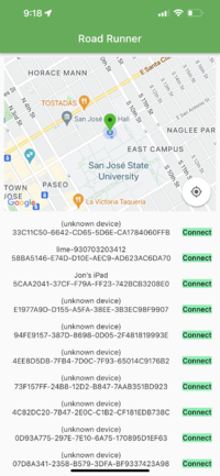
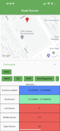
1. The app opens up to show the Google Map with the green marker defaulting to the Engineering Building at SJSU. Once the phone can read the current location of the car, the green marker will update to track the car's location.
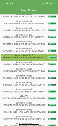
2. The RC Car's Bluetooth Device is named "Adafruit Bluefruit LE" and will be highlighted amongst the list of Bluetooth devices
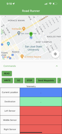
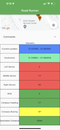
3. Once connected to the RC CAR BLE, the command buttons and telemetry table will appear
4. Pressing the Read button will start reading data from the car and fill the telemetry table with data from the car
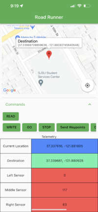
5. Furthermore, a long press on the map will add a destination marker, which the coordinates can be sent to the car by pressing Write
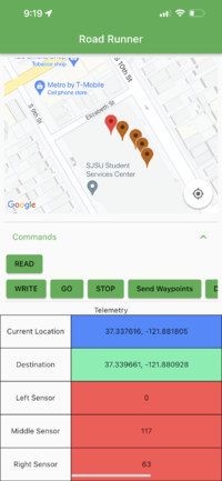
6. Then, waypoints can be added by tapping on the map. The waypoints will be sent once the button "Send Waypoints" is pressed. Also, to clear the waypoints, you need to tap on the info window that appears on the destination marker
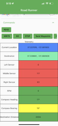
7. Telemetry window shows data read from the SJ2 board, the data is parsed from CAN messages like current location, destination, sensor values, RPM, compass heading and bearing, and distance to destination
8. The buttons can be hidden away to focus on the telemetry table and the map.
Bridge-Sensor Node Firmware Gitlab
Hardware Design
Using the Adafruit BLE Module, we're able to send data from the SJ2 board to the module using UART. Then BLE module then sends the data in packets to the connected mobile phone. By using UART, we can simply print data to the UART to communicate between the Bridge Node and the mobile phone.
Software Design
Code Modules called periodically on the SJ2 board:
- board_processor for reading, parsing and sending data between the SJ2 board and the mobile phone
- can_handler for reading CAN messages on the CAN bus to send telemetry data to the phone and sending CAN messages when reading from the phone
Technical Challenges
- Issue sending more than 20 bytes of data from phone to SJ2 board
 - Resolved by breaking up packets of data into 20 or fewer bytes
- Issue updating telemetry data fast enough
 - Resolved by calling bridge_processor__send_diagnostics_update_periodic() in the 10Hz periodic callback
- Issue handling different data coming into the phone
 - Resolved by hardcoding the fields to fill in the table
Conclusion
At the end of the day, this is by far the most useful course you will take if you are trying to find work in the embedded systems / firmware industry (one of our teammates got their full-time job this semester pretty much due to this course). However, it takes a lot more effort than you think. You will learn what systems engineering is, why it is hard, and what happens when you don't plan ahead of time. You will get an appreciation for just how hard it is to build anything real that actually works. Trying to accomplish all of this in one semester is very hard, so you have to be smart and efficient to get the most value from this project. Invest in high quality components up front, and buy "off-the-shelf" solutions, so that you have more time to learn about the software and unit tests. This is the most important part to learn from this class. Good luck!
Project Video
Project Source Code
Car Firmware: https://gitlab.com/road-runner-ce243/road-runner-firmware
Mobile App Software: https://gitlab.com/road-runner-ce243/road_runner_app
Advise for Future Students
- Buy the Traxxas car and don't cheap out... trust us T.T
- Test out a few different ultrasonic sensors... the MaxSonic sensors are very unreliable even though they are more expensive
- Test outdoors on the garage early to make sure all your sensors and components can handle the sun and other outdoor features
- Meet weekly, and stay ontop of communication over Slack and WhatsApp
- Practice doing code reviews early in the semester, and actually do them as you start writing code for the different controllers
Acknowledgement
Thank you to Preet for creating this awesome course, and thank you to all the previous students who wrote their project reports which we used as a helpful reference!
