S22: Firebolt
Contents
- 1 FireBolt RC Car
- 2 Abstract
- 3 Objectives & Introduction
- 4 Schedule
- 5 Parts List & Cost
- 6 Printed Circuit Board
- 7 Fabrication
- 8 Power Management
- 9 Challenges
- 10 CAN Communication
- 11 Sensor ECU
- 12 Motor ECU
- 13 Geographical Controller
- 14 Communication Bridge Controller & LCD
- 15 Master Module
- 16 Mobile Application
- 17 Conclusion
FireBolt RC Car
Abstract
The Firebolt project is a path finding and obstacle avoiding RC car. The RC Car can interface with an Android application to get new coordinates to travel to, and will do so all while avoiding obstacles visible by ultrasonic sensors.
Objectives & Introduction
Objectives
- RC car can communicate with an Android application to:
- Receive new coordinates to travel to
- Send diagnostic information to the application
- Emergency stop and start driving
- RC car can travel to received coordinates in an efficient path while avoiding obstacles
- RC car can maintain speed when driving on sloped ground
- Design printed circuit board (PCB) to neatly connect all SJ2 boards
- Design and 3D print sensor mounts for the ultrasonic sensors
- Design a simple and intuitive user interface for the Android application
- Design a DBC file
Introduction
The Firebolt RC car uses 4 SJ2 boards as nodes on the CAN bus
- Driver and LCD
- GEO and path finding
- Sensors and bridge app
- Motor
Team Members & Responsibilities
- Geographical Controller
- Master Controller
- Android Application Developer
- Communication Bridge Controller
- Master Controller
- Sensors Controller
- Hardware Integration
- PCB Designing
Schedule
| Week# | Start Date | End Date | Task | Status |
|---|---|---|---|---|
| 1 |
02/15/2021
|
02/21/2021
|
|
|
| 2 |
02/22/2021
|
02/28/2021
|
|
|
| 3 |
03/01/2021
|
03/07/2021
|
|
|
| 4 |
03/08/2021
|
03/14/2021
|
|
|
| 5 |
03/15/2021
|
03/21/2021
|
|
|
| 6 |
03/22/2021
|
03/28/2021
|
|
|
| 7 |
03/29/2021
|
04/04/2021
|
|
|
| 8 |
04/05/2021
|
04/11/2021
|
|
|
| 9 |
04/12/2021
|
04/18/2021
|
|
|
| 10 |
04/19/2021
|
05/25/2021
|
|
|
| 11 |
04/26/2021
|
05/02/2021
|
|
|
| 12 |
05/03/2021
|
05/09/2021
|
|
|
| 13 |
05/10/2021
|
05/16/2021
|
|
|
| 14 |
05/17/2021
|
05/23/2021
|
|
|
| 15 |
05/27/2021
|
05/30/2021
|
|
|
Parts List & Cost
| Item# | Part Description | Vendor | Qty | Cost |
|---|---|---|---|---|
| 1 | Traxxas 1/10 Scale RC Short Truck | Traxxas [1] | 1 | $239.99 + Tax |
| 2 | RPM Sensor & Mount | Traxxas [2] | 1 | $19.00 + Tax |
| 3 | 2S 7.4V 5000mAh LiPo Battery Pack | Amazon [3] | 2 | $40.69 + Tax |
| 4 | Bluetooth Adapter | Amazon [4] | 1 | $8.99 + Tax |
| 5 | Adafruit Ultimate GPS Breakout | Adafruit [5] | 1 | $39.95 |
| 6 | Adafruit Triple-axis Accelerometer+Magnetometer | Adafruit [6] | 1 | $14.95 |
| 7 | Deans Connector | Amazon [7] | 1 | $8.99 + Tax |
| 8 | Pololu 5V Voltage Regulator | Pololu [8] | 1 | $10.83 |
| 9 | PCB | JLCPCB [9] | 1 | $40.00 |
| 10 | CAN transceiver | Amazon [10] | 4 | $40.00 |
| 11 | Maxbotix MB1010 LV-MaxSonar-EZ1 Ultra Sonic Sensors | Maxbotix [11] | 5 | $121.50 |
Printed Circuit Board
Challenges
Fabrication
PCB Properties:
Power Management
Challenges
CAN Communication
Hardware Design
<Show your CAN bus hardware design>
DBC File
Sensor ECU
Hardware Design
Sensor Mounts and Placement
Sensor Range Readings Extraction
Software Design
Technical Challenges
Motor ECU
Hardware Design
| SJ2 Board Pin | Description |
|---|---|
| 5V | Input power |
| 3.3V | CAN transceiver power |
| PWM2 P2.1 | DC Motor Speed Control |
| PWM5 P2.4 | Servo Motor Control |
| CAP0 P2.6 | Input Capture for RPM Sensor |
| CAN1 TX | CAN Module Tx |
| CAN1 RX | CAN Module Rx |
| GND | Grounding |
DC Motor and ESC
The DC motor and ESC were provided with RC car. The DC motor is controlled by the ESC using PWM signals which were provided by the motor controller board for forward, neutral, and reverse movements. The ESC is powered ON using a 7.4 LiPo battery. The ESC converts this 7.4V to 6V and provides input to DC Motor.

| ESC wires | Description | Wire Color |
|---|---|---|
| Vout | Output Power (6V) | RED |
| GND | Ground | BLACK |
| PWM | PWM input from SJ2-Board (P2.1) | WHITE |
The car can be operated at 100Hz in the following 3 modes :
Sport Mode (100% Forward, 100% Brakes, 100% Reverse)
Racing Mode (100% Forward, 100% Brakes, No Reverse)
Training Mode (50% Forward, 100% Brakes, 50% Reverse)
The PWM frequency for our Traxxas ESC needed to be 100Hz. An idle (motor stopped) duty cycle is 15%. The full duty cycle range is [10%, 20%], where [10%, 15%) is the reverse range, and (15%, 20%] is the forward range. We ended up limiting the duty cycle range to [13%, 17%] since the RC car had more power than we needed.
Servo Motor

| Servo Wires | Description | Wire Color |
|---|---|---|
| Vin | Input Voltage (6V) | RED |
| GND | Ground | BLACK |
| PWM | PWM input from SJ2-Board (P2.4) | WHITE |
The PWM frequency for our Traxxas Servo motor also needed to be 100Hz. An idle (wheel's pointing forward) duty cycle is 15%. The full duty cycle range is [10%, 20%], where [10%, 15%) is the steer left range, and (15%, 20%] is the steer right.
Wheel Encoder
For speed sensing we purchased a Traxxas RPM sensor as it mounted nicely in the gearbox. The RPM sensor works by mounting a magnet to the spur gear and a hall effect sensor fixed to the gearbox. To get the revolutions per second we used Timer2 as an input capture.

| RPM Sensor Wires | Description | Wire Color |
|---|---|---|
| Vin | Input Voltage (6V) | RED |
| GND | Ground | BLACK |
| Sensor Output | Input Capture to SJ2-Board (P2.6) | WHITE |
Software Design
The motor controller code modules consisted of 3 main parts, which are: 1. PWM drivers and motor logic, 2. RPM/speed sensor, 3. PID controller.
1. PWM drivers and motor logic
The PWM drivers were fairly easy to write since the SJ2 project provided an API for the low level function calls. Converting speed and angle values to duty cycle values was done by simply linearly mapping one onto the other. This worked fine for steering control, but due to varying grades the car needs to drive on, the PID is needed. The Traxxas ESC, as other students have discovered in the past, has safeguards to prevent damage to the motor by not allowing duty cycle to abruptly change from a forward signal to a reverse. The Traxxas transmitter uses a trigger for this, but as other students suggested, we used a state machine to transition into opposite directions. We found that going from reverse to forward simply requires stopping (15% duty cycle) the car first, while going from forward to reverse required sending the following signals: STOP, REVERSE, STOP, REVERSE. Since we did not consult with Traxxas, this logic was created through trial and error. Transitioning into the opposite direction might simply just require stopping first, and then delay until a speed is reached, then change directions. We had access to an oscilloscope, however we did not capture what actually happens to the DC motor duty cycle when the transmitter does the same transition.
We created a separate module that encapsulated the motor's drive logic, such as getting speed feedback to compute PID value, updating the DC motor and servo motor's PWM in a state machine, and doing the start up self test. Another feature we incorporated was to have the motor controller listen for a message from the Bridge/App, so we could easily start and stop the car remotely. This feature was very helpful in testing.
Later on we also added the feature to run the Traxxas ESC setup by pushing a push button at start up. You need to hold the ESC button when you turn on the car until the green light turns red, then push SW3 on the motor board to run the ESC setup. The setup is fairly simple, it puts the DC motor PWM in full forward (20%) for 3 seconds, full reverse (10%) for 3 seconds, then neutral (15%) for 3 seconds before returning a true for finishing. The function is called in a periodic and the counts are kept track of internally by the function. The 3 seconds was a guess, but it seemed to work fine.
2. RPM/speed sensor
To count the time interval between pulses the RPM sensor makes, we used one of the LPC's peripheral timers that allowed for an input capture feature. We configured the hardware registers such that a capture register is written the value of the timer count register when the input capture (pulse from RPM sensor) occurs. This required writing a low level API so that we could unit test the hardware reading and writing. An interrupt also triggers on a capture event to reset the timer counter, to make the value in the capture register easy to convert to revolutions per second. The circumference of the car's tire and spur gear ratio are needed to determine a scalar value to convert the revolutions per second to conventional speed units. Many students said the RPM sensor from Traxxas was inconsistent and unreliable for speed feedback. We thought that this might be because of how the sensor is measuring the speed of the spur gear and that the differential of the car might cause variation, however when the car goes in a straight line that should not be a problem. When we integration tested the software design with the PID using the above approach, the speed readings seemed stable enough for use with the PID.
3. PID controller
For situations where the DC motor needs to do more or less work (e.g. driving uphill or downhill) the linear mapping will not work. The proportional, integral, derivative (PID) controller is a widely used control mechanism to ensure a machine maintains a set point, and responds quickly and smoothly upon disturbances. In discrete time the integration becomes a summation and the derivative becomes a difference. The controller is based on an error from the set point, which is why the RPM sensor is needed to get feedback. The PID algorithm is fairly simple, as is tuning the gains. We found that the proportional and integral gains were enough to get the car to maintain speed.
The way we tuned the PID was to start off by only using the proportional controller at a unity gain. We had the car drive on level ground and tested at 3kph and 5kph drive speeds. We varied the proportional gain until we saw the car have a "stop and go" motion. Then we dropped the proportional gain in half and tested again with a low integral gain. We now started testing on ground with a grade to see if speed could be maintained. We varied the integral gain until we were satisfied with the DC motor's response to varying terrain.
Below is our design for the motor controller's periodic callbacks.
Periodic Callbacks Initialize:
- Initialize:
- CAN bus
- DC motor PWM
- Servo motor PWM
- RPM sensor input capture
- PID
- Motor logic
Periodic Callbacks 1Hz
- Reset CAN bus if bus goes off
- Have LED indicate CAN bus running status
- Transmit motor debug message
- Transmit motor CAN status
Periodic Callbacks 10Hz
- At 2Hz transmit motor speed
- Update steering angle and drive speed
- Run ESC setup once user pushes button (Optional, can be bypassed)
- At board power up a self test routine is ran (Also optional, but usually ran)
- After the self test, Driver & Bridge/App controller commands are followed
Periodic Callbacks 100Hz
- At 20Hz receive all messages from CAN bus and update local motor data structure


Technical Challenges
- Getting the state machine right for the DC motor to transition between forward and reverse, and vice versa, took some experimentation. Luckily other student's reports were available for us to get hints on what we needed to do.
- When first tuning the PID our boards were attached via jumper wires and breadboard on a piece of plexiglass. The plexiglass was not rigidly secured to the car either, which resulted in collisions with walls and wires becoming undone. All this led to more hardware issues and had us backtrack to get the PID tuned. Making sure the hardware is sound before doing full integration tests will save you time. This requires planning out the hardware early on, and preferably just getting a PCB manufactured.
- We were having problems during integration testing where the motors would not run. It's hard to say what the solution was for certain, but slowing down the rate we updated the PWMs (from 20Hz to 10Hz) seemed to be it.
- We damaged the ESC somehow and needed to purchase another. This cost us time and money. Make sure you don't accidentally short the ESC!
- Some unit tests were not written until after integration testing. This goes against test driven development, but due to deadlines we had to make a choice. Had we thought out the use cases of our modules and wrote unit tests sooner, I'm sure we would have avoided some in the field debugging.
- The code had to be redesigned for modularity and readability later on. Make sure to avoid software anti-patterns, like "blob," and use dependency injection to prevent tightly coupled code modules.
- We damaged one of the LiPo batteries we purchased because we drained the voltage below 3V per cell. Luckily we had another LiPo for testing, but having a voltage sensor to indicate to the app the battery level could be a good idea.
Geographical Controller
https://gitlab.com/infallibleprogrammer/utah/-/tree/master/projects/GEO_Controller
<Picture and link to Gitlab>
Hardware Design
The geographical controller runs all the processing for compass data as well as GPS data. The purpose of the controller is to interface with the Adafruit Ultimate GPS Breakout using UART which provides accurate GPS data formatted in GPGGA. The controller utilizes I2C protocol to interface with the Adafruit Magnetometer with tilt compensation for the purpose of finding our heading and where the car needs to point in order to get closer to its destination. The Adafruit magnetometer was able to give us accurate data with a possible deviation of up to 3 degrees in any direction. This was possible by using a software filter to normalize our data and create a standard.

| SJTwo Board | GPS/Compass Module | Description | Protocol/Bus |
|---|---|---|---|
| P4.28 (TX3) | RX | Adafruit GPS Breakout | UART 3 |
| P4.29 (RX3) | TX | Adafruit GPS Breakout | UART 3 |
| P0.10 (SDA2) | SDA | Adafruit Magnetometer | I2C 2 |
| P0.10 (SCL2) | SCL | Adafruit Magnetometer | I2C 2 |
| P0.1 (SCL1) | CAN transceiver (Tx) | CAN transmit | CAN |
| P0.0 (SDA1) | CAN transceiver (Rx) | CAN receive | CAN |
| Vcc 3.3V | Vcc | Vcc | |
| GND | GND | Ground |
Software Design
The GEO controller consisted of 4 main parts which are: 1. GPS Driver and Processing, 2. Compass Processing, 3.Waypoints Algorithm, and 4. Geo Logic. The geo logic takes data from parts 1 to 3 and determines where the car should be moving. This data is sent to the driver controller via the canbus.
1. GPS Driver and Processing
The GPS module uses UART3 to communicate with our SJ2 board. The API call for the GPS driver requires setting up the gps registers to only allow GPGGA data as well as refresh data every 10hz(100ms) instead of 1hz(1 second). This solve a lot of initial issues with getting stale data as the car moved. The main API function is called gps__run_once() which digests data from the physical GPS hardware. Inside gps__run_once(), we call two functions that help with parsing the gps coordinates. The first is taking using a line buffer for the UART characters that are digested during operation and checking if they are in fact a full GPGGA string. The second function parses those coordinates from the line buffer and converts them from GPGGA minutes data to polar coordinates. Once the function is called, global static variables located in gps.c are used while a gps__get_coorindate() function is called whenever the API's data wants to be used outside of the gps.c file. In order to check if there is a gps fix, we created a function that checks if certain GPGGA bits are set or not. If the are set, than we have a fix. This was more accurate than the FIX pin located on the GPS module because of that pin toggles every 150ms even when their is a fix.
2.Compass Processing
The compass module was one of the trickiest parts of the GEO controller due to the necessary calibrations that came with the code. The compass is initialized to use I2C as a method for communicating with the SJ2 board. The API is primarily one function to get the latest, compass__run_once_get_heading(). This float function is split into three parts: get magnetometer data, get accelerometer data, and use both of those datasets to figure out the heading. The accelerometer was not used in the initial stages of development but was required to accommodate for tilt when the car was moving at high speeds. The compass required a lot of calculations to determine heading, and accommodate for tilt.
Heading Computation:
The lsm303DLHC magnetometer and acceletometer require tilt compensation to ensure accurate readings. If there is not tilt compensation, the compass heading can be up to 60 degrees off making it widely inaccurate. Once proper software based calculations were made, the compass was at most 3 degrees off. A software model was used to normalize the data and reduced noise related to bad readings. Compass Tilt Calculation Software Model for Compass
Normalize Data:
 float alpha = 0.25; // alpha to create base for software optimizations
 static float Mxcnf;
 static float Mycnf;
 static float Mzcnf;
 static float Axcnf;
 static float Aycnf;
 static float Azcnf;
 float norm_m =
     sqrtf(magnetometer_processed.x * magnetometer_processed.x + magnetometer_processed.y * magnetometer_processed.y +
           magnetometer_processed.z * magnetometer_processed.z); // normalize data between all 3 axis
 float Mxz = magnetometer_processed.z / norm_m;
 float Mxy = magnetometer_processed.y / norm_m;
 float Mxx = magnetometer_processed.x / norm_m;
 float norm_a = sqrtf(accel_raw_data.x * accel_raw_data.x + accel_raw_data.y * accel_raw_data.y +
                      accel_raw_data.z * accel_raw_data.z);
 float Axz = accel_raw_data.z / norm_a;
 float Axy = accel_raw_data.y / norm_a;
 float Axx = accel_raw_data.x / norm_a;
 Mxcnf = Mxx * alpha + (Mxcnf * (1.0 - alpha));
 Mycnf = Mxy * alpha + (Mycnf * (1.0 - alpha));
 Mzcnf = Mxz * alpha + (Mzcnf * (1.0 - alpha));
 // Low-Pass filter accelerometer
 Axcnf = Axx * alpha + (Axcnf * (1.0 - alpha));
 Aycnf = Axy * alpha + (Aycnf * (1.0 - alpha));
 Azcnf = Axz * alpha + (Azcnf * (1.0 - alpha));
- Notes:
- Mxcnf: Normalized Magnetometer X Data
- Mycnf: Normalized Magnetometer Y Data
- Mzcnf: Normalized Magnetometer Z Data
- Axcnf: Normalized Accelerometer X Data
- Aycnf: Normalized Accelerometer Y Data
- Azcnf: Normalized Accelerometer Z Data
The normalize data model shown above takes the magnetometer and accelerometer data that has been bit shifted and saved to a static function located in compass.c. The data is divided by the normalized data set for all 3 axis. This occurs for both the accelerometer and magnetometer. Once this data is taken, a low-pass filter is applied where the previous value of the data is used to check for deviation and offsets. An alpha of .25 is used to accommodate for a 75% threshold for deviations in the data during a given time frame. This data is later fed into the tilt compensation algorithm.
Tilt Calculations:
 float pitch = asin(-Axcnf);
 float roll = asin(Aycnf / cos(pitch));
 float Xh = Mxcnf * cos(pitch) + Mzcnf * sin(pitch);
 float Yh = Mxcnf * sin(roll) * sin(pitch) + Mycnf * cos(roll) -
            Mzcnf * sin()roll) * cos(pitch);
 current_compass_heading = (atan2(Yh, Xh)) * 180 / PI;
 current_compass_heading += 13;
 if (current_compass_heading < 0) {
   current_compass_heading = 360 + current_compass_heading;
 }
Pitch and roll are a fundamental part of calculating the tilt. Pitch accounts for deviations in terms of the Y axis while roll is around the X axis. In the calculation seen above, pitch takes the asin of the negation of Axcnf(normalized x axis data for the accelerometer). Roll on the other hand is the ration of normalized y axis data over the cosine of pitch. These are used for the formula seen directly below it. The compass heading is adjusted 13 degrees due to our offset from true north. We need to use the true north value because the data sent to us by google maps compensates for true north. If we encounter an angle below 360, than we get its complement by adding 360 to ensure the rest of our calculations are correct.
3.Waypoints
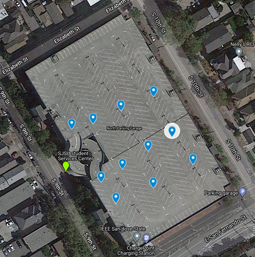
The waypoints algorithm worked in a very simple way but was proven to be affective. The usage of waypoints are used as a way to 3D map obstacles related to the terrain of the SJSU 10th street garage. As shown in the map below, we had 11 overall waypoints and a majority of them are located around the ramp located on the left side of the map. As shown in the map, we utilized waypoints in such a way to ensure that they went around the ramp, rather than through it. This was to avoid the hazard of the RC car believing it can go straight when in fact it can not due to the circular ramp. The points were also created in a line so that the RC car did not unnecessarily go towards the ramp because it was the closest waypoint. If we had a line of points, than it would calculate the point closest to itself and go towards the one. We also wanted to avoid redundant waypoints so we reduced the original 20 waypoints to 11. The checkpoint API looked flow is shown below.


Distance Calculations:
 // a = sin²(Δlatitude/2) + cos(destination_lat) * cos(origin_lat) * sin²(Δlongitude/2)
 // c = 2 * atan2(sqrt(a), sqrt(1−a))
 // d = (6371 *1000) * c
 const int Earth_Radius_in_km = 6371;
 const float delta_lat = (origin.latitude - destination.latitude) * (PI / 180);
 const float delta_long = (origin.longitude - destination.longitude) * (PI / 180);
 float a = pow(sinf(delta_lat / 2), 2) +
           cosf(destination.latitude * (PI / 180)) * cosf(origin.latitude * (PI / 180)) * pow(sin(delta_long / 2), 2);
 float c = 2 * atan2f(sqrt(a), sqrt(1 - a));
 return (float)(Earth_Radius_in_km * c * 1000);
In order to get the calculation for distance, we must accommodate for the curvature of the Earth as well as the radius. In the equation above, we see haversine translated into C code which allows us the compute the distance in meter. This is done in the find_next_point() API call where we calculate the distance from origin to waypoint and waypoint to destination. We are looking for closest point that reduce the distance to the destination. If both of those statements are true, then we set that as our waypoint.
4.Geo Logic
The geo logic was the primary API that allows the GEO controller to function. It takes data from waypoints.c, gps.c, and compass.c. The data is used and processed such that it may be send on the canbus. The geo_logic.c file primarily outputs dbc structs that are utilized in the can_module.c. With the implementation of waypoints, a lot of the calculation in geo_logic.c is no longer needed and will be editted out in the near future. At its current state the main functions in the API are geo_controller_processs_GEO_current_location() which gets the current GPS location for the RC car, geo_controllerprocess_geo_dat() which takes in the gps_destination sent by the bridge controller, and determine_destination_location() which tells the car where to go.

The geo logic was kept simple on purpose. We get our current location, then find out if a destination was sent to our static array. If no, new destination was received than we continue to determine if a waypoint is required to the destination. If the waypoint is used, then those values will be used for get_bearing(). We continue to process the read repeatedly for the 200ms cycle of the periodic scheduler. The task is that simple. If a new destination is appended then we add it and compute if we should go to that new destination first. The maximum allowed destinations is 5 by user design.
Geo Controller Periodics:
Periodic Callbacks Initialize:
- Initialize:
- CAN bus
- gps__init
- compass__init
Periodic Callbacks 1Hz
- If not sent yet, send the GPS instructions to only receive GPGGA data and 10hz refresh rate
- Get compass update values
- Send debug messages every 1 second
Periodic Callbacks 10Hz
- Run the API gps__run_once() to fetch the latest data.
- Use data to determine bearing and heading of first waypoint/destination
- Send this information to the driver for processing
- Receive all messages on the canbus that are designated for us
Technical Challenges
Communication Bridge Controller & LCD
Hardware Design
Software Design
Bridge Controller
Technical Challenges
Master Module
Hardware Design
|
|
Software Design
Technical Challenges
Mobile Application
Hardware Design
Software Design
Technical Challenges
Conclusion
Project Source Code
Advise for Future Students
Acknowledgement
References
Motor Controller