S21: UTAH
Contents
- 1 UTAH: Unit Tested to Avoid Hazards
- 2 Abstract
- 3 Objectives & Introduction
- 4 Schedule
- 5 Parts List & Cost
- 6 Printed Circuit Board
- 7 Fabrication
- 8 Power Management
- 9 Challenges
- 10 CAN Communication
- 11 Sensor ECU
- 12 Motor ECU
- 13 Geographical Controller
- 14 Communication Bridge Controller & LCD
- 15 Master Module
- 16 Mobile Application
- 17 Conclusion
UTAH: Unit Tested to Avoid Hazards

Abstract
The UTAH (Unit Testing to Avoid Hazards) project is a path finding and obstacle avoiding RC car. UTAH can interface with an Android application to get new coordinates to travel to, and will do so all while avoiding obstacles visible by ultrasonic sensors.
Objectives & Introduction
Objectives
- RC car can communicate with an Android application to:
- Receive new coordinates to travel to
- Send diagnostic information to the application
- Emergency stop and start driving
- RC car can travel to received coordinates in an efficient path while avoiding obstacles
- RC car can maintain speed when driving on sloped ground
- Design printed circuit board (PCB) to neatly connect all SJ2 boards
- Design and 3D print sensor mounts for the ultrasonic sensors
- Design a simple and intuitive user interface for the Android application
- Design a DBC file
Introduction
The UTAH RC car uses 4 SJ2 boards as nodes on the CAN bus
- Driver and LCD
- GEO and path finding
- Sensors and bridge app
- Motor
Need a top down photo of RC car
Team Members & Responsibilities

- Akash Vachhani Gitlab
- Leader
- Geographical Controller
- Master Controller

- Jonathan Beard Gitlab
- Android Application Developer
- Communication Bridge Controller
- Ameer Ali
- Master Controller

- Jonathan Tran Gitlab
- Sensors Controller
- Amritpal Sidhu
- Motor Controller

- Shreevats Gadhikar Gitlab'
- Motor Controller
Schedule
| Description | Color |
|---|---|
| Administrative | Black |
| Sensor | Cyan |
| Bluetooth & App | Blue |
| GEO | Red |
| Motor | Magenta |
| Main | Orange |
| Week# | Start Date | End Date | Task | Status |
|---|---|---|---|---|
| 1 |
02/15/2021
|
02/21/2021
|
|
|
| 2 |
02/22/2021
|
02/28/2021
|
|
|
| 3 |
03/01/2021
|
03/07/2021
|
|
|
| 4 |
03/08/2021
|
03/14/2021
|
|
|
| 5 |
03/15/2021
|
03/21/2021
|
|
|
| 6 |
03/22/2021
|
03/28/2021
|
|
|
| 7 |
03/29/2021
|
04/04/2021
|
|
|
| 8 |
04/05/2021
|
04/11/2021
|
|
|
| 9 |
04/12/2021
|
04/18/2021
|
|
|
| 10 |
04/19/2021
|
05/25/2021
|
|
|
| 11 |
04/26/2021
|
05/02/2021
|
|
|
| 12 |
05/03/2021
|
05/09/2021
|
|
|
| 13 |
05/10/2021
|
05/16/2021
|
|
|
| 14 |
05/17/2021
|
05/23/2021
|
|
|
| 15 |
05/24/2021
|
05/30/2021
|
|
|
Parts List & Cost
| Item# | Part Description | Vendor | Qty | Cost |
|---|---|---|---|---|
| 1 | Traxxas 1/10 Scale RC Short Truck | Traxxas [1] | 1 | $239.99 + Tax |
| 2 | RPM Sensor & Mount | Traxxas [2] | 1 | $19.00 + Tax |
| 3 | 2S 7.4V 5000mAh LiPo Battery Pack | Amazon [3] | 2 | $40.69 + Tax |
| 4 | Bluetooth Adapter | Amazon [4] | 1 | $8.99 + Tax |
| 5 | Adafruit Ultimate GPS Breakout | Adafruit [5] | 1 | $39.95 |
| 6 | Adafruit Triple-axis Accelerometer+Magnetometer | Adafruit [6] | 1 | $14.95 |
| 7 | Deans Connector | Amazon [7] | 1 | $8.99 + Tax |
| 8 | Pololu 5V Voltage Regulator | Pololu [8] | 1 | $10.83 |
| 9 | PCB | JLCPCB [9] | 1 | $40.00 |
| 10 | CAN transceiver | Amazon [10] | 4 | $40.00 |
Printed Circuit Board
We started with a very basic design for our RC car on a breadboard. All the components were integrated on the breadboard for testing purposes.

Challenges
The wiring on the breadboard succeeded on the first attempt but later when we kept adding the components as per the requirements the wiring became a complete mess and was entangling everywhere due to which the car could not navigate properly. Every time the car collided, the wires used to get disconnected. So reconnecting the wires and debugging the hardware every time after the collision was the main challenge. So we decided to go with PCB.
We later had a PCB manufactured. In our design we minimized the use of surface mount components and additional passive components. We reused the CAN transceiver modules we all purchased and the only passive components on the board were the two 120Ω termination resistors needed at each end of the CAN bus. The remainder of the PCB used a combination of male and female pin headers to connect all components together. This design and implementation were succeeded in the first attempt.


To overcome all the challenges which were faced on the breadboard we designed the PCB on EasyEDA. EasyEDA allows the creation and editing of schematic diagrams, and also the creation and editing of printed circuit board layouts and, optionally, the manufacture of printed circuit boards. So we implemented the custom PCB using EasyEDA software in which we implemented all the four controller connections. The four controllers included Master Controller, Geo Controller, Sensor Controller, and Motor Controller. The communication of these four controllers is done via a CAN bus. The GPS and Compass are connected to the Geo controller. The four Matbotix Ultrasonic sensors (three in front and one in rear) and the Bluetooth module are connected to the sensor controller board, while the LCD and LEDs are connected to Master Controller. RPM sensor, DC motor, and Servo motor are connected to Motor Controller. Also, all four CAN transceivers are connected to their respective board.
Fabrication
Using the EasyEDA we designed a 2 layer PCB. PCB was sent to fabrication to JLCPCB China which provided PCB within 7 days with MOQ of 5. The dimension of the PCB was 12.5" * 4.5" (332.61mm * 129.54mm). The four controllers were placed at the four corners of the PCB while the other components were placed at the center.
PCB Properties:
Size: 332.61mm * 129.54mm
Signal Layers: 2
Componenets: 35
Routing width: 0.254mm
Track Width: 1mm
Clearance: 0.3mm
Via diameter: 0.61mm
Via Drill Diameter: 0.31mm
Vias: 20
Power Management
The main power came from a 7.4v Lipo battery. This 7.4v from the battery was given to ECS. ESC gave a power output of 6V. This 6V was given to the Pololu voltage regulator. We used 5V Step-Up/Step-Down Voltage Regulator S9V11F5 for powering our four controllers and their respective components. The S9V11F5 helps in switching step-up/step-down regulator efficiently to produces 5V from input voltages between 2 V and 16 V. Its ability to convert both higher and lower input voltages makes it useful for applications where the power supply voltage can vary greatly, it's suitable for application where we use a battery. The Pololu is a very compact (0.3″ × 0.45″) module and also has a typical efficiency of over 90% and can supply a typical output current of up to 1.5 A when the input voltage is around 5 V.

Challenges
1. Calculating the power requirement for each device.
2. Getting the pinout information for every controller.
3. Using only one battery was a challenge.
4. Splitting the power to 3.3V, 5V, 6V from one battery to different components.
5. Finding the pitch and dimensions of each component and placing them in the correct place and orientation.
6. Finding the correct power IC which can serve all the requirements.
7. Routing the wires on the PCB.
CAN Communication
<Talk about your message IDs or communication strategy, such as periodic transmission, MIA management etc.>
Our message IDs were chosen based upon an agreed priority scheme. We assigned high priority IDs to messages that controlled the movement of the car, followed by sensor and GEO messages, and lowest priority messages were for debug and status.
Debug and status messages were sent in the 1Hz, and a few in the 10Hz, callbacks. The sensor and driver boards send data at the fastest rate (20Hz), so receiving all messages is done at 20Hz as well.
Each board managed MIAs using the auto generated API. Each board received all messages in one function call, and the service MIA function would be executed if messages a board was expecting did not arrive. The increment and threshold values for MIA were in units of milliseconds, so it was easy to adjust threshold values if we wanted a MIA to occur earlier or later.
Hardware Design
<Show your CAN bus hardware design>
DBC File
VERSION ""

NS_ :
	BA_
	BA_DEF_
	BA_DEF_DEF_
	BA_DEF_DEF_REL_
	BA_DEF_REL_
	BA_DEF_SGTYPE_
	BA_REL_
	BA_SGTYPE_
	BO_TX_BU_
	BU_BO_REL_
	BU_EV_REL_
	BU_SG_REL_
	CAT_
	CAT_DEF_
	CM_
	ENVVAR_DATA_
	EV_DATA_
	FILTER
	NS_DESC_
	SGTYPE_
	SGTYPE_VAL_
	SG_MUL_VAL_
	SIGTYPE_VALTYPE_
	SIG_GROUP_
	SIG_TYPE_REF_
	SIG_VALTYPE_
	VAL_
	VAL_TABLE_

BS_:

BU_: DBG DRIVER IO MOTOR SENSOR GEO


BO_ 100 BRIDGE_APP_COMMANDS: 1 SENSOR
 SG_ APP_COMMAND : 0|2@1+ (1,0) [0|0] "" GEO,DRIVER

BO_ 101 MOTOR_CHANGE_SPEED_AND_ANGLE_MSG: 2 DRIVER
 SG_ DC_MOTOR_DRIVE_SPEED_sig : 0|8@1+ (0.1,-10) [-10|10] "kph" MOTOR
 SG_ SERVO_STEER_ANGLE_sig : 8|8@1+ (1,-45) [-45|45] "degrees" MOTOR

BO_ 102 SENSOR_SONARS_ROUTINE: 5 SENSOR
 SG_ SENSOR_SONARS_left : 0|10@1+ (1,0) [0|0] "inch" DRIVER
 SG_ SENSOR_SONARS_right : 10|10@1+ (1,0) [0|0] "inch" DRIVER
 SG_ SENSOR_SONARS_middle : 20|10@1+ (1,0) [0|0] "inch" DRIVER
 SG_ SENSOR_SONARS_rear : 30|10@1+ (1,0) [0|0] "inch" DRIVER

BO_ 300 GPS_DESTINATION_LOCATION: 8 SENSOR
 SG_ DEST_LATITUDE : 0|32@1+ (0.000001,-90.000000) [-90|90] "Degrees" GEO
 SG_ DEST_LONGITUDE : 32|32@1+ (0.000001,-180.000000) [-180|180] "Degrees" GEO

BO_ 301 COMPASS_HEADING_DISTANCE: 6 GEO
 SG_ CURRENT_HEADING : 0|12@1+ (0.1,0) [0|359.9] "Degrees" DRIVER,SENSOR
 SG_ DESTINATION_HEADING: 12|12@1+ (0.1,0) [0|359.9] "Degrees" DRIVER,SENSOR
 SG_ DISTANCE : 24|17@1+ (0.01,0) [0|0] "Meters" DRIVER,SENSOR

BO_ 501 GPS_CURRENT_INFO: 8 GEO
 SG_ GPS_CURRENT_LAT : 0|32@1+ (0.000001,-90.000000) [-90|90] "degrees" DRIVER,SENSOR,MOTOR
 SG_ GPS_CURRENT_LONG : 32|32@1+ (0.000001,-180.000000) [-180|180] "degrees" DRIVER,SENSOR,MOTOR

BO_ 502 GPS_COMPASS_STATUS : 1 GEO
 SG_ COMPASS_LOCK_VALID: 0|1@1+ (1,0) [0|0] "TRUE_FALSE" DRIVER, SENSOR
 SG_ GPS_LOCK_VALID : 1|1@1+ (1,0) [0|0] "TRUE_FALSE" DRIVER,SENSOR,MOTOR

BO_ 503 GPS_CURRENT_DESTINATIONS_DATA: 8 GEO
 SG_ CURRENT_DEST_LATITUDE : 0|32@1+ (0.000001,-90.000000) [-90|90] "Degrees" DRIVER
 SG_ CURRENT_DEST_LONGITUDE : 32|32@1+ (0.000001,-180.000000) [-180|180] "Degrees" DRIVER

BO_ 504 RC_CAR_SPEED_READ_MSG: 2 MOTOR
  SG_ RC_CAR_SPEED_sig : 0|8@1+ (0.1,-10) [-10|10] "kph" DRIVER,SENSOR

BO_ 750 DBG_RAW_COMPASS_DATA: 4 GEO
  SG_ SIGNED_REGISTER_VAL_MAG_X : 0|16@1+ (1.0,0) [-2048|2047] "GAUSSIAN" DRIVER,SENSOR
  SG_ SIGNED_REGISTER_VAL_MAG_Y : 16|16@1+ (1.0,0) [-2048|2047] "GAUSSIAN" DRIVER,SENSOR

BO_ 751 DBG_CONFIRM_RECEIVED_DESTINATION: 8 GEO
 SG_ RECEIVED_DEST_LATITUDE : 0|32@1+ (0.000001,-90.000000) [-90|90] "Degrees" SENSOR
 SG_ RECEIVED_DEST_LONGITUDE : 32|32@1+ (0.000001,-180.000000) [-180|180] "Degrees" SENSOR

BO_ 775 DBG_GPS_COMPASS_LOCK_LED_CHECK: 1 GEO
 SG_ COMPASS_LED_STATUS: 0|1@1+ (1,0) [0|0] "TRUE_FALSE" DRIVER, SENSOR, MOTOR
 SG_ GPS_LED_STATUS : 1|1@1+ (1,0) [0|0] "TRUE_FALSE" DRIVER, SENSOR, MOTOR

BO_ 780 DBG_GEO_CAN_STATUS: 3 GEO
 SG_ DBG_CAN_INIT_STATUS: 0|1@1+ (1,0) [0|0] "TRUE_FALSE" DRIVER, SENSOR, MOTOR
 SG_ DBG_CAN_RX_DROP_COUNT : 1|16@1+ (1,0) [0|0] "TRUE_FALSE" DRIVER,SENSOR,MOTOR

BO_ 781 DBG_SENSOR_CAN_STATUS: 3 SENSOR
 SG_ DBG_CAN_INIT_STATUS: 0|1@1+ (1,0) [0|0] "TRUE_FALSE" DRIVER, GEO, MOTOR
 SG_ DBG_CAN_RX_DROP_COUNT : 1|16@1+ (1,0) [0|0] "drops" DRIVER,GEO,MOTOR

BO_ 782 DBG_MOTOR_CAN_STATUS: 3 MOTOR
 SG_ DBG_CAN_INIT_STATUS: 0|1@1+ (1,0) [0|0] "TRUE_FALSE" DRIVER, SENSOR, GEO
 SG_ DBG_CAN_RX_DROP_COUNT : 1|16@1+ (1,0) [0|0] "TRUE_FALSE" DRIVER,SENSOR,GEO

BO_ 783 DBG_DRIVER_CAN_STATUS: 3 DRIVER
 SG_ DBG_CAN_INIT_STATUS: 0|1@1+ (1,0) [0|0] "TRUE_FALSE" GEO, SENSOR, MOTOR
 SG_ DBG_CAN_RX_DROP_COUNT : 1|16@1+ (1,0) [0|0] "TRUE_FALSE" GEO,SENSOR,MOTOR

BO_ 784 DBG_MOTOR_INFO_MSG: 4 MOTOR
  SG_ DBG_DC_MOTOR_CURRENT_PWM_sig: 0|8@1+ (0.1,0) [10|20] "duty percent" DRIVER
  SG_ DBG_SERVO_MOTOR_CURRENT_PWM_sig : 8|8@1+ (0.1,0) [10|20] "duty percent" DRIVER
  SG_ DBG_PID_OUTPUT_VALUE_sig : 16|8@1+ (0.1,0) [0|0] "kph" DRIVER
  SG_ DBG_MOTOR_SELF_TEST_sig : 24|1@1+ (1,0) [0|0] "TRUE_FALSE" DRIVER

BO_ 001 DRIVER_HEARTBEAT: 1 DRIVER
 SG_ DRIVER_HEARTBEAT_cmd : 0|8@1+ (1,0) [0|0] "" SENSOR,MOTOR

BO_ 002 SENSOR_HEARTBEAT: 1 SENSOR
 SG_ DRIVER_HEARTBEAT_cmd : 0|8@1+ (1,0) [0|0] "" SENSOR,MOTOR

BO_ 003 GEO_HEARTBEAT: 1 GEO
 SG_ DRIVER_HEARTBEAT_cmd : 0|8@1+ (1,0) [0|0] "" SENSOR,MOTOR

BO_ 004 MOTOR_HEARTBEAT_MSG: 1 MOTOR
  SG_ MOTOR_HEARTBEAT_sig : 0|8@1+ (1,0) [0|255] "pulse" DRIVER

CM_ BU_ DRIVER "The driver controller driving the car";
CM_ BU_ MOTOR "The motor controller of the car";
CM_ BU_ SENSOR "The sensor controller of the car";
CM_ BO_ 100 "Sync message used to synchronize the controllers";
CM_ SG_ 100 DRIVER_HEARTBEAT_cmd "Heartbeat command from the driver";

BA_DEF_ "BusType" STRING ;
BA_DEF_ BO_ "GenMsgCycleTime" INT 0 0;
BA_DEF_ SG_ "FieldType" STRING ;

BA_DEF_DEF_ "BusType" "CAN";
BA_DEF_DEF_ "FieldType" "";
BA_DEF_DEF_ "GenMsgCycleTime" 0;

BA_ "GenMsgCycleTime" BO_ 100 1000;
BA_ "GenMsgCycleTime" BO_ 200 50;
BA_ "FieldType" SG_ 100 DRIVER_HEARTBEAT_cmd "DRIVER_HEARTBEAT_cmd";

VAL_ 100 DRIVER_HEARTBEAT_cmd 2 "DRIVER_HEARTBEAT_cmd_REBOOT" 1 "DRIVER_HEARTBEAT_cmd_SYNC" 0 "DRIVER_HEARTBEAT_cmd_NOOP" ;
Sensor ECU
<Picture and link to Gitlab>
Hardware Design
The sensor of choice for UTAH, was the LV-MAXSonar-EZ1 MB1010. The LV-MAXSonar-EZ1 comes in five different models for the ultrasonic sensor. These models are the MB1000, MB1010, MB1020, MB1030, and MB1040. The models are based on the beam width of the sensor. MB1000 has the widest beam pattern where as MB1040 has the narrowest. It was decided that the MB1010 model will be better suited for object detection. If the beam pattern is too wide given the MB1000, there is a greater chance of cross talk between sensors. If the beam pattern is too narrow, there may be blind spots which must be accounted for. Thus, four LV-MAXSonar-EZ1 MB1010 sensors were used. Three sensors were placed in the front and one in the rear of the vehicle. It will be noted that the SJTWO board is configured to have three ADC channels. Thus to account for a fourth sensor, the DAC was configured to be an ADC channel. More of this configuration will be discussed in the software design.


Sensor Mounts and Placement
Sensor mounts were 3D printed and attached to the front and rear bumper of the RC car. The prints were created such that GoPro mounts were attachable. The GoPro mounts allowed the sensors to tilt and rotate to a desired position. The 3D prints were created by David Brassfield. David was not a part of team UTAH, however, his contribution to our project was crucial. Thus, we deeply appreciate his craftsmanship and his contribution to our project.
The sensors were positioned and angled away from eachother to minimize cross talk. Whereas, the GoPro mounts allowed the sensors to be tilted away from the ground to avoid an object being "detected". During initial testing without the mounts, objects were being "detected" as the pulse of the sensors would collide with the ground. However, tilting the sensors upward may cause objects to not be detected or be seen as further away. Through trial and error, the correct tilt was found and fixed to that position for each sensor.


Sensor Range Readings Extraction
To extract range readings from the MB1010, the "AN" pin which represents analog output was utilized. A range reading is commanded by triggering the "RX" pin high for 20us or more. The output analog voltage is based on a scaling factor of (Vcc/512) per inch. All four of the sensors were powered from the SJTWO board, thus a 3.3v VCC was supplied to each sensor. According to the LV-MaxSonar-EZ datasheet, with 3.3v source, the analog output was expected to be roughly 6.4mV/inch. However, when initially testing the output range readings, the output was completely inaccurate. It was soon found out that the ADC channels for the SJTWO are configured at start up to have an internal pull up resistor. Disabling this pull up resistor will be discussed more in Software Design. Once this solution was resolved, the range readings were more accurate. The readings were tested by having multiple objects placed in front of each sensor and measuring the distance of the object to the sensors. Although the range readings were more accurate, it was found that the range readings did not necessarily follow the expected 6.4mV/inch. As a result, range readings were off by roughly +/- 6 inches. For instance, an object placed 25 inches could have been detected as 31 inches. To account for this, the scaling was adjusted to 8mV/inch. This value was extracted by placing objects around the sensors and checking if the analog output to inch conversion matched to the actual measured distance. The readings with stationary objects were roughly +/- 1 inch which was deemed suitable for object detection.
Software Design
The software design is split into two parts. An ultra sonic sensor module (1.) and a sensor controller module (2.). The ultra sonic module contains functions to initialize the adc channels, initialize the sensors sensors ,and to extract range readings. The sensor controller utilizes the ultra sonic sensor module to initialize and extract range readings from the ultra sonic sensors. In addition, the sensor controller contains the logic to transmit the readings for the front, left, right, and rear sensors over CAN to the driver controller.
1. Ultra Sonic Sensor Module
The ultra_sonic_sensors.h file can be seen below. This module contains an enumeration to specify the position of each sensor. In addition, an ultra_sonic_sensor struct was created to specify trigger pins, positions using the enum, and etc. The module contains basic functions to initialize the adc channels, to initialize the sensors,and to extract range readings. In addition, a median function was added to return the median of the last three data range readings for a given ultra_sonic_sensor.

Initializing the ADC channels
This section is added as a tip for future CMPE 243 students. The SJ2 board is configured for three ADC channels and a single DAC channel. To modify the DAC to be a fourth ADC channel, Preet's ADC API was modified in adc.c. In addition, the source file was modified to disable pull-up resistors. The IOCON registers can be configured following the table descriptions below. Table 86. shows that P0.26 which was configured as a DAC, can be configured for ADC0[3]. Table 85., shows the bit patterns to disable pull-up resistors and to enable analog mode.


2. Sensor Controller
Each sensor was triggered individually every 50ms to get a range reading. The function for the sensor range calculations was placed in the 100hz periodic callbacks function, thus the function was named Sensor_Controller__100hz_handler(). In the periodic callbacks function, the sensor function call would occur at a frequency of 20hz. At the start of the function, a range reading would be extracted for a sensor then transmitted over CAN. After, the next sensor trigger pin would be triggered to command a range reading. Therefore, in the next function call, the range reading will be made available. According to the Maxbotix data sheet, the sensors require 50ms to retrieve a range reading after the "RX" trigger pin has been pulled high for at least 20us.
Accounting for Cross Talk
Originally, each sensor was triggered simultaneously within a 50ms time frame. By doing this, there seemed to be an increase in cross talk between sensors. The range readings can be seen in the plot below, for when no object was placed in front of the sensors and for when an object was placed about 30 inches away from the right sensor. From these plots, we can see the cross talk occurs when an object was placed in front of a sensor. The cross talk causes the left sensor to see an object near the given range in which the object was placed in front of the right sensor. Although the cross talk occurs a few times, this will cause an object to be "detected", thus the car will sway to dodge the object. As a result, if an object is detected on the right sensor, the left sensor may detect an object. Thus, for example, the object avoidance algorithm will call for the RC car to reverse instead of moving left to dodge the object on the right. It will be noted that the rear sensor can be ignored in the plot as it was isolated and moved away for testing purposes. To minimize the cross talk, each sensor are individually triggered every 50ms. This gives each sensor a 50ms time frame to extract a range reading with less interference.


Technical Challenges
< List of problems and their detailed resolutions>
Median Filter
The median function was added as a filtering mechanism. Although cross talk was minimized by having the sensors angled away from each other, there was still occurrences of objects being "detected" even when no objects were within a threshold for object avoidance. Thus, if an object was to be "detected", the RC car will maneuver to avoid the object even if no object was in close proximity. The median function would return the median of the last three range readings. This minimized the chance of false positives occurring for object avoidance. However, this introduced new issues which will be discussed in the technical challenges portion.
Motor ECU
Hardware Design


Motor Controller includes the controlling of the DC motor, Servo motor, Electronic speed control (ESC), and the wheel encoder. The job of the motor controller is both to steer and spin the wheels in order to move the RC car to the target destination. The DC motor, servo motor, and ESC(Traxxas ESC XL-05) were provided with the Traxxas RC car. The wheel encoder was purchased separately from Traxxas's website. The job of the DC motor is to control the spinning of the rear 2 wheels through the utilization of ESC and wheel encoder whereas the job of the servo motor is to control the steering of the front 2 wheels.
| SJ2 Board Pin | Description |
|---|---|
| 5V | Input power |
| 3.3V | CAN transceiver power |
| PWM2 P2.1 | DC Motor Speed Control |
| PWM5 P2.4 | Servo Motor Control |
| CAP0 P2.6 | Input Capture for RPM Sensor |
| CAN1 TX | CAN Module Tx |
| CAN1 RX | CAN Module Rx |
| GND | Grounding |
DC Motor and ESC
The DC motor and ESC were provided with RC car. The DC motor is controlled by the ESC using PWM signals which were provided by the motor controller board for forward, neutral, and reverse movements. The ESC is powered ON using a 7.4 LiPo battery. The ESC converts this 7.4V to 6V and provides input to DC Motor.

| ESC wires | Description | Wire Color |
|---|---|---|
| Vout | Output Power (6V) | RED |
| GND | Ground | BLACK |
| PWM | PWM input from SJ2-Board (P2.1) | WHITE |
The car can be operated at 100Hz in the following 3 modes :
Sport Mode (100% Forward, 100% Brakes, 100% Reverse)
Racing Mode (100% Forward, 100% Brakes, No Reverse)
Training Mode (50% Forward, 100% Brakes, 50% Reverse)
The PWM frequency for our Traxxas ESC needed to be 100Hz. An idle (motor stopped) duty cycle is 15%. The full duty cycle range is [10%, 20%], where [10%, 15%) is the reverse range, and (15%, 20%] is the forward range. We ended up limiting the duty cycle range to [13%, 17%] since the RC car had more power than we needed.
Servo Motor

| Servo Wires | Description | Wire Color |
|---|---|---|
| Vin | Input Voltage (6V) | RED |
| GND | Ground | BLACK |
| PWM | PWM input from SJ2-Board (P2.4) | WHITE |
The PWM frequency for our Traxxas Servo motor also needed to be 100Hz. An idle (wheel's pointing forward) duty cycle is 15%. The full duty cycle range is [10%, 20%], where [10%, 15%) is the steer left range, and (15%, 20%] is the steer right.
Wheel Encoder
For speed sensing we purchased a Traxxas RPM sensor as it mounted nicely in the gearbox. The RPM sensor works by mounting a magnet to the spur gear and a hall effect sensor fixed to the gearbox. To get the revolutions per second we used Timer2 as an input capture.

| RPM Sensor Wires | Description | Wire Color |
|---|---|---|
| Vin | Input Voltage (6V) | RED |
| GND | Ground | BLACK |
| Sensor Output | Input Capture to SJ2-Board (P2.6) | WHITE |
Software Design
The motor controller code modules consisted of 3 main parts, which are: 1. PWM drivers and motor logic, 2. RPM/speed sensor, 3. PID controller.
1. PWM drivers and motor logic
The PWM drivers were fairly easy to write since the SJ2 project provided an API for the low level function calls. Converting speed and angle values to duty cycle values was done by simply linearly mapping one onto the other. This worked fine for steering control, but due to varying grades the car needs to drive on, the PID is needed. The Traxxas ESC, as other students have discovered in the past, has safeguards to prevent damage to the motor by not allowing duty cycle to abruptly change from a forward signal to a reverse. The Traxxas transmitter uses a trigger for this, but as other students suggested, we used a state machine to transition into opposite directions. We found that going from reverse to forward simply requires stopping (15% duty cycle) the car first, while going from forward to reverse required sending the following signals: STOP, REVERSE, STOP, REVERSE. Since we did not consult with Traxxas, this logic was created through trial and error. Transitioning into the opposite direction might simply just require stopping first, and then delay until a speed is reached, then change directions. We had access to an oscilloscope, however we did not capture what actually happens to the DC motor duty cycle when the transmitter does the same transition.
We created a separate module that encapsulated the motor's drive logic, such as getting speed feedback to compute PID value, updating the DC motor and servo motor's PWM in a state machine, and doing the start up self test. Another feature we incorporated was to have the motor controller listen for a message from the Bridge/App, so we could easily start and stop the car remotely. This feature was very helpful in testing.
Later on we also added the feature to run the Traxxas ESC setup by pushing a push button at start up. You need to hold the ESC button when you turn on the car until the green light turns red, then push SW3 on the motor board to run the ESC setup. The setup is fairly simple, it puts the DC motor PWM in full forward (20%) for 3 seconds, full reverse (10%) for 3 seconds, then neutral (15%) for 3 seconds before returning a true for finishing. The function is called in a periodic and the counts are kept track of internally by the function. The 3 seconds was a guess, but it seemed to work fine.
2. RPM/speed sensor
To count the time interval between pulses the RPM sensor makes, we used one of the LPC's peripheral timers that allowed for an input capture feature. We configured the hardware registers such that a capture register is written the value of the timer count register when the input capture (pulse from RPM sensor) occurs. This required writing a low level API so that we could unit test the hardware reading and writing. An interrupt also triggers on a capture event to reset the timer counter, to make the value in the capture register easy to convert to revolutions per second. The circumference of the car's tire and spur gear ratio are needed to determine a scalar value to convert the revolutions per second to conventional speed units. Many students said the RPM sensor from Traxxas was inconsistent and unreliable for speed feedback. We thought that this might be because of how the sensor is measuring the speed of the spur gear and that the differential of the car might cause variation, however when the car goes in a straight line that should not be a problem. When we integration tested the software design with the PID using the above approach, the speed readings seemed stable enough for use with the PID.
3. PID controller
For situations where the DC motor needs to do more or less work (e.g. driving uphill or downhill) the linear mapping will not work. The proportional, integral, derivative (PID) controller is a widely used control mechanism to ensure a machine maintains a set point, and responds quickly and smoothly upon disturbances. In discrete time the integration becomes a summation and the derivative becomes a difference. The controller is based on an error from the set point, which is why the RPM sensor is needed to get feedback. The PID algorithm is fairly simple, as is tuning the gains. We found that the proportional and integral gains were enough to get the car to maintain speed.
The way we tuned the PID was to start off by only using the proportional controller at a unity gain. We had the car drive on level ground and tested at 3kph and 5kph drive speeds. We varied the proportional gain until we saw the car have a "stop and go" motion. Then we dropped the proportional gain in half and tested again with a low integral gain. We now started testing on ground with a grade to see if speed could be maintained. We varied the integral gain until we were satisfied with the DC motor's response to varying terrain.
Below is our design for the motor controller's periodic callbacks.
Periodic Callbacks Initialize:
- Initialize:
- CAN bus
- DC motor PWM
- Servo motor PWM
- RPM sensor input capture
- PID
- Motor logic
Periodic Callbacks 1Hz
- Reset CAN bus if bus goes off
- Have LED indicate CAN bus running status
- Transmit motor debug message
- Transmit motor CAN status
Periodic Callbacks 10Hz
- At 2Hz transmit motor speed
- Update steering angle and drive speed
- Run ESC setup once user pushes button (Optional, can be bypassed)
- At board power up a self test routine is ran (Also optional, but usually ran)
- After the self test, Driver & Bridge/App controller commands are followed
Periodic Callbacks 100Hz
- At 20Hz receive all messages from CAN bus and update local motor data structure


Technical Challenges
- Getting the state machine right for the DC motor to transition between forward and reverse, and vice versa, took some experimentation. Luckily other student's reports were available for us to get hints on what we needed to do.
- When first tuning the PID our boards were attached via jumper wires and breadboard on a piece of plexiglass. The plexiglass was not rigidly secured to the car either, which resulted in collisions with walls and wires becoming undone. All this led to more hardware issues and had us backtrack to get the PID tuned. Making sure the hardware is sound before doing full integration tests will save you time. This requires planning out the hardware early on, and preferably just getting a PCB manufactured.
- We were having problems during integration testing where the motors would not run. It's hard to say what the solution was for certain, but slowing down the rate we updated the PWMs (from 20Hz to 10Hz) seemed to be it.
- We damaged the ESC somehow and needed to purchase another. This cost us time and money. Make sure you don't accidentally short the ESC!
- Some unit tests were not written until after integration testing. This goes against test driven development, but due to deadlines we had to make a choice. Had we thought out the use cases of our modules and wrote unit tests sooner, I'm sure we would have avoided some in the field debugging.
- The code had to be redesigned for modularity and readability later on. Make sure to avoid software anti-patterns, like "blob," and use dependency injection to prevent tightly coupled code modules.
- We damaged one of the LiPo batteries we purchased because we drained the voltage below 3V per cell. Luckily we had another LiPo for testing, but having a voltage sensor to indicate to the app the battery level could be a good idea.
Geographical Controller
https://gitlab.com/infallibleprogrammer/utah/-/tree/master/projects/GEO_Controller
<Picture and link to Gitlab>
Hardware Design
The geographical controller runs all the processing for compass data as well as GPS data. The purpose of the controller is to interface with the Adafruit Ultimate GPS Breakout using UART which provides accurate GPS data formatted in GPGGA. The controller utilizes I2C protocol to interface with the Adafruit Magnetometer with tilt compensation for the purpose of finding our heading and where the car needs to point in order to get closer to its destination. The Adafruit magnetometer was able to give us accurate data with a possible deviation of up to 3 degrees in any direction. This was possible by using a software filter to normalize our data and create a standard.

| SJTwo Board | GPS/Compass Module | Description | Protocol/Bus |
|---|---|---|---|
| P4.28 (TX3) | RX | Adafruit GPS Breakout | UART 3 |
| P4.29 (RX3) | TX | Adafruit GPS Breakout | UART 3 |
| P0.10 (SDA2) | SDA | Adafruit Magnetometer | I2C 2 |
| P0.10 (SCL2) | SCL | Adafruit Magnetometer | I2C 2 |
| P0.1 (SCL1) | CAN transceiver (Tx) | CAN transmit | CAN |
| P0.0 (SDA1) | CAN transceiver (Rx) | CAN receive | CAN |
| Vcc 3.3V | Vcc | Vcc | |
| GND | GND | Ground |
Software Design
The GEO controller consisted of 4 main parts which are: 1. GPS Driver and Processing, 2. Compass Processing, 3.Waypoints Algorithm, and 4. Geo Logic. The geo logic takes data from parts 1 to 3 and determines where the car should be moving. This data is sent to the driver controller via the canbus.
1. GPS Driver and Processing
The GPS module uses UART3 to communicate with our SJ2 board. The API call for the GPS driver requires setting up the gps registers to only allow GPGGA data as well as refresh data every 10hz(100ms) instead of 1hz(1 second). This solve a lot of initial issues with getting stale data as the car moved. The main API function is called gps__run_once() which digests data from the physical GPS hardware. Inside gps__run_once(), we call two functions that help with parsing the gps coordinates. The first is taking using a line buffer for the UART characters that are digested during operation and checking if they are in fact a full GPGGA string. The second function parses those coordinates from the line buffer and converts them from GPGGA minutes data to polar coordinates. Once the function is called, global static variables located in gps.c are used while a gps__get_coorindate() function is called whenever the API's data wants to be used outside of the gps.c file. In order to check if there is a gps fix, we created a function that checks if certain GPGGA bits are set or not. If the are set, than we have a fix. This was more accurate than the FIX pin located on the GPS module because of that pin toggles every 150ms even when their is a fix.
2.Compass Processing
The compass module was one of the trickiest parts of the GEO controller due to the necessary calibrations that came with the code. The compass is initialized to use I2C as a method for communicating with the SJ2 board. The API is primarily one function to get the latest, compass__run_once_get_heading(). This float function is split into three parts: get magnetometer data, get accelerometer data, and use both of those datasets to figure out the heading. The accelerometer was not used in the initial stages of development but was required to accommodate for tilt when the car was moving at high speeds. The compass required a lot of calculations to determine heading, and accommodate for tilt.
Heading Computation:
The lsm303DLHC magnetometer and acceletometer require tilt compensation to ensure accurate readings. If there is not tilt compensation, the compass heading can be up to 60 degrees off making it widely inaccurate. Once proper software based calculations were made, the compass was at most 3 degrees off. A software model was used to normalize the data and reduced noise related to bad readings. Compass Tilt Calculation Software Model for Compass
Normalize Data:
 float alpha = 0.25; // alpha to create base for software optimizations
 static float Mxcnf;
 static float Mycnf;
 static float Mzcnf;
 static float Axcnf;
 static float Aycnf;
 static float Azcnf;
 float norm_m =
     sqrtf(magnetometer_processed.x * magnetometer_processed.x + magnetometer_processed.y * magnetometer_processed.y +
           magnetometer_processed.z * magnetometer_processed.z); // normalize data between all 3 axis
 float Mxz = magnetometer_processed.z / norm_m;
 float Mxy = magnetometer_processed.y / norm_m;
 float Mxx = magnetometer_processed.x / norm_m;
 float norm_a = sqrtf(accel_raw_data.x * accel_raw_data.x + accel_raw_data.y * accel_raw_data.y +
                      accel_raw_data.z * accel_raw_data.z);
 float Axz = accel_raw_data.z / norm_a;
 float Axy = accel_raw_data.y / norm_a;
 float Axx = accel_raw_data.x / norm_a;
 Mxcnf = Mxx * alpha + (Mxcnf * (1.0 - alpha));
 Mycnf = Mxy * alpha + (Mycnf * (1.0 - alpha));
 Mzcnf = Mxz * alpha + (Mzcnf * (1.0 - alpha));
 // Low-Pass filter accelerometer
 Axcnf = Axx * alpha + (Axcnf * (1.0 - alpha));
 Aycnf = Axy * alpha + (Aycnf * (1.0 - alpha));
 Azcnf = Axz * alpha + (Azcnf * (1.0 - alpha));
- Notes:
- Mxcnf: Normalized Magnetometer X Data
- Mycnf: Normalized Magnetometer Y Data
- Mzcnf: Normalized Magnetometer Z Data
- Axcnf: Normalized Accelerometer X Data
- Aycnf: Normalized Accelerometer Y Data
- Azcnf: Normalized Accelerometer Z Data
The normalize data model shown above takes the magnetometer and accelerometer data that has been bit shifted and saved to a static function located in compass.c. The data is divided by the normalized data set for all 3 axis. This occurs for both the accelerometer and magnetometer. Once this data is taken, a low-pass filter is applied where the previous value of the data is used to check for deviation and offsets. An alpha of .25 is used to accommodate for a 75% threshold for deviations in the data during a given time frame. This data is later fed into the tilt compensation algorithm.
Tilt Calculations:
 float pitch = asin(-Axcnf);
 float roll = asin(Aycnf / cos(pitch));
 float Xh = Mxcnf * cos(pitch) + Mzcnf * sin(pitch);
 float Yh = Mxcnf * sin(roll) * sin(pitch) + Mycnf * cos(roll) -
            Mzcnf * sin()roll) * cos(pitch);
 current_compass_heading = (atan2(Yh, Xh)) * 180 / PI;
 current_compass_heading += 13;
 if (current_compass_heading < 0) {
   current_compass_heading = 360 + current_compass_heading;
 }
Pitch and roll are a fundamental part of calculating the tilt. Pitch accounts for deviations in terms of the Y axis while roll is around the X axis. In the calculation seen above, pitch takes the asin of the negation of Axcnf(normalized x axis data for the accelerometer). Roll on the other hand is the ration of normalized y axis data over the cosine of pitch. These are used for the formula seen directly below it. The compass heading is adjusted 13 degrees due to our offset from true north. We need to use the true north value because the data sent to us by google maps compensates for true north. If we encounter an angle below 360, than we get its complement by adding 360 to ensure the rest of our calculations are correct.
3.Waypoints
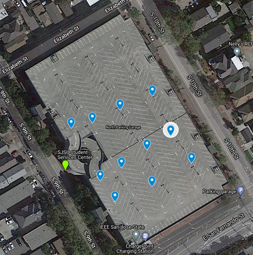
The waypoints algorithm worked in a very simple way but was proven to be affective. The usage of waypoints are used as a way to 3D map obstacles related to the terrain of the SJSU 10th street garage. As shown in the map below, we had 11 overall waypoints and a majority of them are located around the ramp located on the left side of the map. As shown in the map, we utilized waypoints in such a way to ensure that they went around the ramp, rather than through it. This was to avoid the hazard of the RC car believing it can go straight when in fact it can not due to the circular ramp. The points were also created in a line so that the RC car did not unnecessarily go towards the ramp because it was the closest waypoint. If we had a line of points, than it would calculate the point closest to itself and go towards the one. We also wanted to avoid redundant waypoints so we reduced the original 20 waypoints to 11. The checkpoint API looked flow is shown below.


Distance Calculations:
 // a = sin²(Δlatitude/2) + cos(destination_lat) * cos(origin_lat) * sin²(Δlongitude/2)
 // c = 2 * atan2(sqrt(a), sqrt(1−a))
 // d = (6371 *1000) * c
 const int Earth_Radius_in_km = 6371;
 const float delta_lat = (origin.latitude - destination.latitude) * (PI / 180);
 const float delta_long = (origin.longitude - destination.longitude) * (PI / 180);
 float a = pow(sinf(delta_lat / 2), 2) +
           cosf(destination.latitude * (PI / 180)) * cosf(origin.latitude * (PI / 180)) * pow(sin(delta_long / 2), 2);
 float c = 2 * atan2f(sqrt(a), sqrt(1 - a));
 return (float)(Earth_Radius_in_km * c * 1000);
In order to get the calculation for distance, we must accommodate for the curvature of the Earth as well as the radius. In the equation above, we see haversine translated into C code which allows us the compute the distance in meter. This is done in the find_next_point() API call where we calculate the distance from origin to waypoint and waypoint to destination. We are looking for closest point that reduce the distance to the destination. If both of those statements are true, then we set that as our waypoint.
4.Geo Logic
The geo logic was the primary API that allows the GEO controller to function. It takes data from waypoints.c, gps.c, and compass.c. The data is used and processed such that it may be send on the canbus. The geo_logic.c file primarily outputs dbc structs that are utilized in the can_module.c. With the implementation of waypoints, a lot of the calculation in geo_logic.c is no longer needed and will be editted out in the near future. At its current state the main functions in the API are geo_controller_processs_GEO_current_location() which gets the current GPS location for the RC car, geo_controllerprocess_geo_dat() which takes in the gps_destination sent by the bridge controller, and determine_destination_location() which tells the car where to go.

The geo logic was kept simple on purpose. We get our current location, then find out if a destination was sent to our static array. If no, new destination was received than we continue to determine if a waypoint is required to the destination. If the waypoint is used, then those values will be used for get_bearing(). We continue to process the read repeatedly for the 200ms cycle of the periodic scheduler. The task is that simple. If a new destination is appended then we add it and compute if we should go to that new destination first. The maximum allowed destinations is 5 by user design.
Geo Controller Periodics:
Periodic Callbacks Initialize:
- Initialize:
- CAN bus
- gps__init
- compass__init
Periodic Callbacks 1Hz
- If not sent yet, send the GPS instructions to only receive GPGGA data and 10hz refresh rate
- Get compass update values
- Send debug messages every 1 second
Periodic Callbacks 10Hz
- Run the API gps__run_once() to fetch the latest data.
- Use data to determine bearing and heading of first waypoint/destination
- Send this information to the driver for processing
- Receive all messages on the canbus that are designated for us
Technical Challenges
- Adafruit GPS
- Problem: The data from the GPS was being refreshed every second which was causing issues for the RC car. It was swerving too much because of the stale data.
- Solution: Send the command to the GPS for a higher refresh rate(10hz) and only send the SJ2 board GPGGA data.
- Problem: It would take way too long for the GPS to have a fix causing a 3-5 minute way when indoors and over 45 seconds when outside
- Solution: Utilize the external antenna. It was able to get a fix inside in under a minute while outside within 25 seconds.
- Problem: The data from the GPS was being refreshed every second which was causing issues for the RC car. It was swerving too much because of the stale data.
- Compass
- Problem: The heading was widely inaccurate when attempting to see compass reading
- Solution: When calibrating the sensor, do not have any electronics near you. Ensure you have enough distance between the controller and the compass when in the calibration step. This ensures accurate calibration and readings.
- Problem: The data on the compass was very inaccurate when compensating for tilt
- Solution: Utilized magviewer to get proper bias rating for the compass sensor which we used. Data was with 3 degrees of the intended degree
- Problem: The heading was widely inaccurate when attempting to see compass reading
Communication Bridge Controller & LCD
https://gitlab.com/jbeard79/UTAH_APP/-/tree/user/jbeard79/%231/SensorReading
Hardware Design
The bridge controller and sensor controllers were merged together on one board. For the hardware pinout, view the schematic located in the sensor controller section.
The hardware for the controller is a very straight forward design. The HC-05 Bluetooth modules is connected to the bridge controller via UART. The phone used for testing purposes must have a Bluetooth capabilities. For this reason, an emulated phone was unable to be used for anything except graphics and viewing purposes.
To configure the HC-05, a Raspberry Pi 4 was setup to terminal into the HC-05 over UART. This site was helpful in the setup: https://www.instructables.com/Modify-The-HC-05-Bluetooth-Module-Defaults-Using-A/. One note, a few sites showed the command for setting the baud rate to be +AT+BAUD=____. This was invalid for the HC-05 and requires the +AT_UART= Baud, stop, parity.
Software Design
Bridge Controller
To avoid mismatching data, a sort of semi brute force method was used for the messaging. All messages are decoded in the 10hz periodic every cycle. The Bluetooth messages are sent in chunks in the 10 Hz periodic to avoid the overlapping of the messages, sending groups of messages at one time. The grouping is as follows: Driver and motor messages, GEO, then Sensors. MIA checks for all messages is done in the 1 Hz periodic. This setup was extremely helpful for identifying if a board was flashed with the incorrect code or stopped sending messages that were supposed to be sent.
Technical Challenges
There were only a few challenges faced with the Bridge Controller.
The largest problem was actually sending data to the App in a timely manner. Converting all of the messages to strings to send through bluetooth was found to be too slow and would result in messages crossing over on top of one another. Even with the UART baud rate increased to the maximum speed of 115,200 for the HC-05, the messages would blur together at times. The easiest fix was to only populate the some of the messages in a given 10hz callback. Only two of the boards were able to be grouped together to send, motor and driver. The other controllers' messages were sent in one time slot.
The other difficult part was working in tandem with the Sensor Controller code and ensure both of us were using the correct branch and most updated code.
Master Module
<Picture and link to Gitlab>
Hardware Design
The Master node is primarily responsible for issuing commands to the Motor node to go towards target waypoints. It takes information from both the Geo and Sensor nodes and preforms its own calculations based on that information to make the proper turns and speed changes. It is also responsible for outputting relevant data such as Distance to target, Current Heading, and Speed to the connected RPIgear LCD screen for easy viewing of the data while the car is in motion

|
|
Software Design

<List the code modules that are being called periodically.>
Technical Challenges
< List of problems and their detailed resolutions>
Mobile Application
https://gitlab.com/jbeard79/UTAH_APP/-/tree/user/jbeard79/%231/SensorReading


Hardware Design
The phone used was an older Trackphone running Android OS.
Software Design

When the app first opens the Bluetooth socket that is created is checked if it is NULL, which it should be with startup. If this occurs the Bluetooth connection screen will be brought up, shown as the far right picture above, and the user will need to tap a device to attempt a connection. If the connection fails, the screen will again be brought up. Once a connection is established with the Bridge Controller the main screen, shown as the far left picture, will be brought up. The first thing that can be seen is the Map. A few precautions were taken so nothing would happen to the map's camera when the user attempts to click on the map while the GPS is not sending accurate data. A blue pin is used to represent the car's current location once good data is being received. When this data is updated, this pin's location is refreshed and redrawn onto the map. A default destination is used for the 10th street garage for some ease of testing and to accommodate camera repositioning. The camera is repositioned to the averaged of the destination and the current location. Once the desired destination is selected, the latitude and longitude of the selection will be displayed under the map. The car can be started by pressing the Send Coordinates button located at the bottom of the scroll window. This will send coordinates, truncated down to a float instead of a double, onto the can bus.
Technical Challenges
Connecting to google maps was much easier than anticipated. The tutorial here: https://developers.google.com/maps/documentation/android-sdk/start, is a great way to add the map portion in.
Thinking about message format and structure early was key. Setting up with good modular design saved a lot of time after it was implemented and made the code much easier to read.
One other thing to note when using google maps, an account must be setup and a key is used for the app to connect. That key is located in the googlemapsapi file, and is ignored in git by default when using Android Studios. Double checking that your key is not included in your pushes is helpful to ensure your key is not leaked.
Conclusion
<Organized summary of the project>
<What did you learn?>
This is a challenging project on its own, but despite the additional difficulties that came with remote learning we were able to finish many of our objectives and learned many lessons along the way. This project covers multiple disciplines, from mechanical engineering, electrical engineering, computer science, and even project management, some of which none of us had prior experience in. During our time working on this project we furthered our understanding of embedded systems and good software design patterns, such as test driven development, while learning new information as well. Interfacing with ultrasonic sensors and doing signal processing on the data, interfacing with a GPS module, determining heading from a magnetometer and incorporate tilt compensation using an accelerometer, write firmware for a Bluetooth module and communicate with and Android application that we made, interface with electric motors using PWM and create a PID to control speed, designing a PCB, not to mention our deep dive into the CAN protocol and not only learning the intricacies of the protocol but designing our own CAN messages in a DBC file and writing firmware to have our controllers communicate. Many of these tasks required research to get an understanding of concepts before we could even implement anything.
All these tasks were made more challenging with the remote learning as some of us were not always in close proximity to the campus so that we could troubleshoot problems quickly and with access to labs. Some of us were working full time jobs while taking the course, making time management hard and creating exhaustion. We had moments of frustration when integration testing threw roadblocks our way, but we managed to persevere and get a functional demo by the end of the class.
Looking back, we could have probably created a better plan earlier on. Defining milestones for different nodes, and if they were not reached, shift our attention to get them done to progress the overall project. We overlooked a lot of the mechanical aspects of the RC car and how it would impact the compass and accelerometer. Improving our mounting and spending more time refining the process of determining heading would have likely helped a lot. Refining driver logic to deal with some variability in steering, that we did not notice until integration testing near the final weeks, earlier on could also have helped in the performance of the car in the final demo. These are learning points that we will keep in mind for future projects and add to the takeaways from the course.
<add some inspirational final paragraph here>
Project Video
Project Source Code
Advise for Future Students
1. It is advised to order the parts as soon as possible and determine the pin/ports which are needed to begin the designing and ordering of the PCB.
2. Select good quality components. Don't go for cheap quality components.
3. Always have extra components. You never know which component will stop working. Having extra components saves a lot of time.
4. Use all the CAN transceivers of the same manufacturer.
5. Try to use one power source instead of two for the entire project. In this way, you can reduce the overall weight of your RC car.
6. Select your Power Regulator IC wisely. You need to have sufficient current to drive all the controllers and the components.
Acknowledgement
References
Motor Controller