Difference between revisions of "S20: Nimble"
(→GPS) |
(→GPS) |
||
| Line 627: | Line 627: | ||
=== Hardware Interface === | === Hardware Interface === | ||
==== GPS ==== | ==== GPS ==== | ||
| − | + | The GPS is responsible for sending GPS NMEA sentences to the Geographical controller to parse and tokenize in order to get the current latitude and longitude in the units, degrees:hours:minutes:seconds. The sentence desired to extract the coordinates is the GPGGA sentence which contains fixed GPS coordinates. The GPS module that we used for this project was the "Ultimate GPS breakout board" from Adafruit. The module was interfaced with the UART2 port of the SJTwo LPC4078 Controller with a baud rate of 9600 and with 1 stop bit. | |
<table> | <table> | ||
Revision as of 06:51, 21 May 2020
Contents
- 1 Nimble Autonomous RC Car
- 2 Abstract
- 3 Team Members & Responsibilities
- 4 Team Deliverables Schedule
- 5 Parts List & Cost
- 6 Printed Circuit Board
- 7 CAN Communication
- 8 Sensor ECU
- 9 Motor ECU
- 10 Geographical Controller
- 11 Communication Bridge Controller & LCD
- 12 Driver Module
- 13 Mobile Application
- 14 Conclusion
Nimble Autonomous RC Car


Abstract
In this project, an autonomous vehicle framework for an RC car is presented using dedicated ECUs for motor control, on-board LCD display, steering control, sensor information handling, and communication bridging. A mobile application was also developed that allows for a user to set a destination, and receive updates on the RC car's position via a Bluetooth connection to the GPS unit. CAN communication between sensors and ECUs was defined via a DBC file. Code was developed using test-driven design principles in order to lower time spent debugging. Unit testing was performed using the CMock framework.
Introduction
The project was divided into these modules:
- Sensor node
- Motor node
- Driver node
- GPS node
- Bridge control node
- LCD node
- Mobile application
The objective was to create an autonomous vehicle that could navigate to a given GPS coordinate sent via a mobile application. The vehicle moves towards the target position Using a pre-compiled list of checkpoints, and handles obstacles along the way via its ultrasonic and infrared sensors. Updates on Nimble's position are sent to the mobile application via bluetooth.

Team Members & Responsibilities
<Team Picture>
- Yuming Cheng [ LinkedIn] Gitlab
- GPS Module
- Master Module
- Motor Module
- LCD display
- RC Integration and testing
- Wiki
- Naeem Mannan [ LinkedIn] Gitlab
- Wiki
- Mobile Application
- Francesco Vescio [ LinkedIn] Gitlab
- Wiki
- Code Review
- Lawrence Wan LinkedIn Gitlab
- Driver Module
- GPS Module
- Motor Module
- LCD display
- Sensor Module
- RC Integration and testing
- Wiki
Team Deliverables Schedule
| WEEK |
START DATE |
END DATE |
TASK DETAILS |
STATUS |
|---|---|---|---|---|
| 1 | Feb 2020 | 4 March 2020 |
|
|
| 2 | 05 March 2020 | 12 March 2020 |
|
|
| 3 | 13 March 2020 | 19 March 2020 |
|
|
| 4 | 20 March 2020 | 26 March 2020 |
|
|
| 5 | 27 March 2019 | 09 April 2019 |
|
|
| 6 | 10 April 2020 | 16 April 2020 |
|
|
| 7 | 17 April 2020 | 23 April 2020 |
|
|
| 8 | 24 April 2020 | 30 April 2020 |
|
|
| 9 | 1 May 2020 | 7 May 2020 |
|
|
| 10 | 8 May 2020 | 21 May 2020 |
|
|
| 11 | 22 May 2020 |
|
|
Parts List & Cost
| Item# | Part Desciption | Vendor | Qty | Cost |
|---|---|---|---|---|
| 1 | RC Car | Traxxas - Amazon [1] | 1 | $168.84 |
| 2 | CAN Transceivers MCP2551-I/P | Robotshop [2] | 6 | $ 6.00 per unit including shipping fee |
| 3 | GPS | Amazon [] | 1 | $ .00 per unit including shipping fee |
| 4 | Compass | Amazon [] | 1 | $ .00 per unit including shipping fee |
| 5 | Ultrasonic sensors(LV-MaxSonar-EZ0) | SparkFun [3] | 1 | $ 29.95 |
| 6 | Ultrasonic sensors (LV-MaxSonar-EZ1) | SparkFun [4] | 2 | $ 51.90 |
| 7 | IR sensors (GP2Y0A21YK) | SparkFun [5] | 1 | $ 34.23 including shipping fee and tax |
Printed Circuit Board
Design and Architecture
The PCB made for the Project Nimble RC car was initially designed in EAGLE, however, due to the board size limitations, the PCB had to be designed using DipTrace instead. This design was the first and only iteration in designing the layout of the PCB. The design of the PCB was designed around the four SJTWO LPC4078 micro-controllers required for us to use for the project, the DRIVER, MOTOR, GEOGRAPHICAL, and BRIDGE/SENSOR nodes. The PCB layout consists of four through-hole "slots" where the controllers will be connected (with respect to the controllers' orientation and ports/pins) to the PCB. The power section includes a USB socket as well as a through-hole mount for a LM7805 regulator. Through-hole header pins are also included for the components needed for their respective controllers such as the sensors, LCD, GPS, Compass, etc.. LED circuits were added to provide visual information for the user to indicate the motor and servo motion states, as well as to indicate if a sensor has detected an object. Lastly, the design for the CAN bus includes the connections needed for power, RX/TX, and the CAN low and CAN high bus. The dimensions of the PCB are approximately 4 by 9 inches.
Fabrication
Fabrication of the PCB design was done by JLCPCB located in Hong Kong. The PCB was designed using 2-layers and lead-free coating. The fabrication was done relatively quickly, however, due to the COVID-19 outbreak, delivery of the PCB was delayed.
Challenges
Some challenges encountered when designing the PCB was the delay in pinout information needed to begin designing the PCB. It is advised to order parts early and determine what ports/pins are needed as soon as possible to begin designing and ordering the PCB. Another challenge was some issues with the files needed to be manufactured. Since the design had to be designed using DipTrace instead of EAGLE, exporting the necessary files needed to order for fabrication is slightly different than EAGLE.


CAN Communication
<Talk about your message IDs or communication strategy, such as periodic transmission, MIA management etc.>
Hardware Design
<Show your CAN bus hardware design>
DBC File
<Gitlab link to your DBC file> <You can optionally use an inline image>
Shown below is the DBC implementation for this project.
VERSION ""

NS_ :
	BA_
	BA_DEF_
	BA_DEF_DEF_
	BA_DEF_DEF_REL_
	BA_DEF_REL_
	BA_DEF_SGTYPE_
	BA_REL_
	BA_SGTYPE_
	BO_TX_BU_
	BU_BO_REL_
	BU_EV_REL_
	BU_SG_REL_
	CAT_
	CAT_DEF_
	CM_
	ENVVAR_DATA_
	EV_DATA_
	FILTER
	NS_DESC_
	SGTYPE_
	SGTYPE_VAL_
	SG_MUL_VAL_
	SIGTYPE_VALTYPE_
	SIG_GROUP_
	SIG_TYPE_REF_
	SIG_VALTYPE_
	VAL_
	VAL_TABLE_

BS_:

BU_: DBG DRIVER IO MOTOR SENSOR BRIDGE GPS COMPASS CMP

BO_ 150 MOTOR_CMD: 3 DRIVER
 SG_ MOTOR_CMD_STEERING : 0|8@1+ (1,-2) [-2|2] "" MOTOR
 SG_ MOTOR_CMD_SPEED : 8|8@1+ (1,-25) [-25|25] "" MOTOR

BO_ 151 MOTOR_DATA: 4 MOTOR
 SG_ MOTOR_DATA_RPM: 0|32@1+ (1,0) [0|0] "" DRIVER

BO_ 200 SENSOR_DATA: 8 BRIDGE
 SG_ SENSOR_SONARS_left : 0|16@1+ (1,0) [0|0] "cms" DRIVER
 SG_ SENSOR_SONARS_mid : 16|16@1+ (1,0) [0|0] "cms" DRIVER
 SG_ SENSOR_SONARS_right : 32|16@1+ (1,0) [0|0] "cms" DRIVER
 SG_ SENSOR_IR_rear : 48|16@1+ (1,0) [0|0] "cms" DRIVER

BO_ 300 GPS_DESTINATION_INFO: 8 BRIDGE
SG_ GPS_DESTINATION_LAT : 0|32@1+ (0.000001,-90.000000) [-90|90] "degrees" DRIVER,GPS,MOTOR
SG_ GPS_DESTINATION_LONG : 32|32@1+ (0.000001,-180.000000) [-180|180] "degrees" DRIVER,GPS,MOTOR

BO_ 301 GPS_CURRENT_INFO: 8 GPS
SG_ GPS_CURRENT_LAT : 0|32@1+ (0.000001,-90.000000) [-90|90] "degrees" DRIVER,BRIDGE,MOTOR
SG_ GPS_CURRENT_LONG : 32|32@1+ (0.000001,-180.000000) [-180|180] "degrees" DRIVER,BRIDGE,MOTOR

BO_ 302 COMPASS: 6 GPS
 SG_ CMP_DEST_BEARING : 0|16@1+ (0.1,0) [0|359.9] "degrees" DRIVER,BRIDGE,MOTOR
 SG_ CMP_CURRENT_HEADING : 16|16@1+ (0.1,0) [0|359.9] "degrees" DRIVER,BRIDGE,MOTOR
 SG_ CMP_DISTANCE : 32|16@1+ (0.01,0) [0|0] "meters" DRIVER,BRIDGE

BO_ 105 SENSOR_DEBUG: 1 BRIDGE
 SG_ IO_DEBUG_CAN_init : 0|1@1+ (1,0) [0|0] "" DBG
 SG_ IO_DEBUG_sensor_init : 1|1@1+ (1,0) [0|0] "" DBG
 SG_ IO_DEBUG_sensor_data : 2|1@1+ (1,0) [0|0] "" DBG
 SG_ IO_DEBUG_bus_off : 3|1@1+ (1,0) [0|0] "" DBG

BO_ 106 MOTOR_DEBUG: 6 MOTOR
 SG_ IO_DEBUG_CAN_init : 0|1@1+ (1,0) [0|0] "" DBG,DRIVER
 SG_ IO_DEBUG_bus_off : 1|1@1+ (1,0) [0|0] "" DBG,DRIVER
 SG_ IO_DEBUG_Steering : 2|8@1+ (1,-2) [-2|2] "" DBG,DRIVER
 SG_ IO_DEBUG_RPM : 10|32@1+ (1,0) [0|0] "" DBG,DRIVER

BO_ 107 DRIVER_DEBUG: 1 DRIVER
 SG_ IO_DEBUG_CAN_init : 0|1@1+ (1,0) [0|0] "" DBG
 SG_ IO_DEBUG_bus_off : 1|1@1+ (1,0) [0|0] "" DBG
 SG_ IO_DEBUG_DRIVER : 3|1@1+ (1,0) [0|0] "" DBG

BO_ 108 GPS_DEBUG: 1 GPS
 SG_ IO_DEBUG_CAN_init : 0|1@1+ (1,0) [0|0] "" DBG
 SG_ IO_DEBUG_bus_off : 2|1@1+ (1,0) [0|0] "" DBG
 SG_ IO_DEBUG_GPS : 3|1@1+ (1,0) [0|0] "" DBG
 SG_ IO_DEBUG_Compass : 5|1@1+ (1,0) [0|0] "" DBG

BO_ 109 BRIDGE_DEBUG: 1 BRIDGE
 SG_ IO_DEBUG_CAN_init : 0|1@1+ (1,0) [0|0] "" DBG
 SG_ IO_DEBUG_bus_off : 2|1@1+ (1,0) [0|0] "" DBG
 SG_ IO_DEBUG_Bridge : 4|1@1+ (1,0) [0|0] "" DBG

CM_ BU_ DRIVER "The driver controller driving the car";
CM_ BU_ MOTOR "The motor controller of the car";
CM_ BU_ BRIDGE "The bridge controller of the car";
CM_ BU_ GPS    "The GPS controller of the car";
CM_ BO_ 100 "Sync message used to synchronize the controllers";
CM_ SG_ 100 DRIVER_HEARTBEAT_cmd "Heartbeat command from the driver";

BA_DEF_ "BusType" STRING ;
BA_DEF_ BO_ "GenMsgCycleTime" INT 0 0;
BA_DEF_ SG_ "FieldType" STRING ;

BA_DEF_DEF_ "BusType" "CAN";
BA_DEF_DEF_ "FieldType" "";
BA_DEF_DEF_ "GenMsgCycleTime" 0;

BA_ "GenMsgCycleTime" BO_ 100 1000;
BA_ "FieldType" SG_ 100 DRIVER_HEARTBEAT_cmd "DRIVER_HEARTBEAT_cmd";

VAL_ 100 DRIVER_HEARTBEAT_cmd 2 "DRIVER_HEARTBEAT_cmd_REBOOT" 1 "DRIVER_HEARTBEAT_cmd_SYNC" 0 "DRIVER_HEARTBEAT_cmd_NOOP" ;
Sensor ECU
<Picture>
The sensor and bridge controller consists of sensor module that is responsible for object detection. Nimble uses ultrasonic sensors to achieve this task. As the name suggests, an ultrasonic sensor emits ultrasonic signal or beam from its head, and on encountering an object, returns back. This technique is better known as echolocation as we used sound signals to do so. The distance of the object is calculated based on the output and this ensures object detection. The distance measured is continuously passed on to driver node through can transceiver. The driver controller further processes the distance values of all the sensors on nimble and acts in accordance with the values to achieve obstacle avoidance.
Hardware Design
We have embedded 4 sensors on Nimble. We have arranged 3 LV-MaxSonar-EZ series Maxbotix ultrasonic sensors in the front section of the car; one at right, one at left and one in the center. The fourth Ultrasonic sensor is placed at the rear end of the car. These sensors provide very short to long-range detection. It provides sonar range information from 6-inches out to 254-inches with 1-inch resolution.


A maxbotix sensor gives out 3 types of output- analog, RS232, and Pulse width. We have used analog output and hence, utilized on-board analog to digital converters- ADC2 (P0.25), ADC3 (P0.26), ADC4 (P1.30), and ADC5 (P1.31). To trigger all the four ultrasonic sensors, we used P0.6, P0.7, P0.8 and P0.9 of SJTWO board. The analog output is converted to digital and transmitted to the driver controller. The converted adc distance data is passed to driver by Can transceiver. P0.0 is used as CAN RX and P0.1 as CAN TX on the Sensor module.
Hardware Interface
Sensors are interfaced with combination of GPIO, ADC Pins on SJTWo board. Below is the descriptive pin layout:
| Sr. No. | SJTwo board Pin | Maxbotix sensor Pin | Function |
|---|---|---|---|
| 1 | ADC2-P0.25 | AN(Left) | ADC input from left sensor |
| 2 | ADC3-P0.26 | AN(Rear) | ADC input from rear sensor |
| 3 | ADC4-P1.30 | AN(Right) | ADC input from right sensor |
| 4 | ADC5-P1.31 | AN(Middle) | ADC input from middle sensor |
| 5 | P0.6 | RX(Right) | Trigger for right sensor |
| 6 | P0.7 | RX(Left) | Trigger for left sensor |
| 7 | P0.8 | RX(Middle) | Trigger for middle sensor |
| 8 | P0.9 | RX(Rear) | Trigger for rear sensor |
Software Design
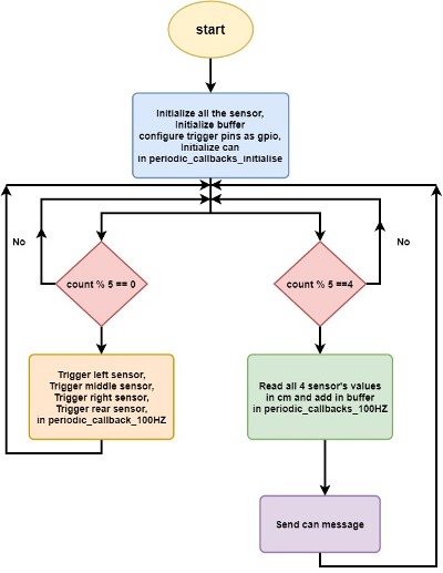
The sensor implementation is mostly done in 100HZ function of periodic callbacks. The basic operation objective is to trigger all the sensors whenever (count%5==0) one after another and get the converted minimum distance value from ADC readings every time (count%5 ==4). As we have used Analog output, we used on board ADC and we had to make few changes in the ADC driver. The SJTWO board has 4 ADC but the pin out diagram showed only 3 and misnamed one ADC with DAC (P0.26). So we added P0.26 that is ADC3 channel into the code and modified the ADC driver accordingly. The ADC readings are basically in form of raw voltage and hence are converted to distances in centimetres. To get the most accurate distance value of each sensor, we used buffer that gives out the minimum distance reading. This distance is sent over CAN to driver controller which further processes these distances and coordinates the movement of car accordingly. The flowchart below shows the implementation of our sensor controller.

A. Initialization:
1. Initialization of sensors: As we are using on board ADC to get voltage, we first initialize all the ADCs (ADC2, ADC 3, ADC 4, ADC 5). We then configured IOCON registers to set up all the ADC’s.
2. Initialized Buffer and can.
B. Triggering the sensors:
1. Configured the SJTWO pin connected to sensor’s RX as GPIO output. This pin will be served as trigger pin to the sensors.
2. The sensors are triggered in 100Hz functions. To do so, trigger pin is set for 30 microseconds and the reset.
3. Triggered all the sensors every time (count%5==0) one after other, starting with left, right, middle and lastly rear.
C. Read sensor values:
We are using ADC values to obtain the distance. All the values are in form of analog voltage and represents number of steps in terms of voltage level. To get real voltage value from raw, it is multiplied by adc voltage and divided by voltage scaling defined by voltage level powering the sensors (here 3.3 V) and manufacturing scaling (Vcc/512). The distance values obtained are stored in buffer. All the sensors have individual buffer that collects the distance values and get the minimum of all the values.
D. CAN transmission:
The lowest distance in cm of all the sensors are sent to driver controller over CAN bus. We have used CAN1 to achieve this task. The driver then coordinates the movement according to the distance value.
Technical Challenges
< List of problems and their detailed resolutions>
Motor ECU
<Picture of ECU>
Hardware Design
Software Design
<List the code modules that are being called periodically.>
Technical Challenges
< List of problems and their detailed resolutions>
Geographical Controller
The geographical controller is responsible for interfacing with a GPS and Compass module in order to receive the current heading(in degrees) and the current destination in the form of GPS coordinates (in degrees, hours, minutes, seconds). It is also responsible for receiving the needed destination coordinates sent by the BRIDGE controller which are needed along with the current GPS location coordinates to calculate the destination heading angle and distance to destination and checkpoints. The current compass heading angle is also sent to the DRIVER controller such that it can be integrated into the driver logic to determine the heading angle to steer and drive towards the destination.
Hardware Design

Hardware Interface
GPS
The GPS is responsible for sending GPS NMEA sentences to the Geographical controller to parse and tokenize in order to get the current latitude and longitude in the units, degrees:hours:minutes:seconds. The sentence desired to extract the coordinates is the GPGGA sentence which contains fixed GPS coordinates. The GPS module that we used for this project was the "Ultimate GPS breakout board" from Adafruit. The module was interfaced with the UART2 port of the SJTwo LPC4078 Controller with a baud rate of 9600 and with 1 stop bit.
|

Compass
|

Software Design
High-level software flow of the geographical controller
.jpg)


Technical Challenges
- Issue 1: Probably one of the most difficult challenges to deal with in this project was the inaccuracy of the GPS module. The default readings of this GPS module would be read were not even remotely close to its actual location.
- Solution: Although we did not fully fix this issue, the method that we dealt with the terrible accuracy was to implement manual calibration with respect to the actual location of the module using google maps, and either adding or subtracting an offset to the GPS coordinates received from the GPS module.
- Issue 2: Calibration of the compass was another issue. Each time the compass module would boot up, the readings of the heading angle would be off by a considerable amount.
- Solution: The solution to solve this was to send calibration commands to the compass module. Helpful commands to send to the compass was erasing the calibration profile and setting default calibration settings.
Communication Bridge Controller & LCD
<Picture and link to Gitlab>
Hardware Design
Software Design
<List the code modules that are being called periodically.>
Technical Challenges
< List of problems and their detailed resolutions>
Driver Module
<Picture and link to Gitlab>
Hardware Design
Software Design
<List the code modules that are being called periodically.>
Technical Challenges
< List of problems and their detailed resolutions>
Mobile Application
<Picture and link to Gitlab> https://gitlab.com/Project-Nimble/sjtwo-c/-/tree/react-app is the branch that has the main workings of the React-app development.
Hardware Design
Software Design
<List the code modules that are being called periodically.> The software's main front end code was written in Javascript while the backend was written in Python flask to send and receive data from the micro controller to the app. The methods of sending GPS coordinates from the the app to the microcontroller was using a location's address or a point and click map from google. To receive the data from the microcontroller, the data had to be sent from the bluetooth module in a specific way such that python could parse through the data and then separate it into sensor and sensor value. The sent data would be picked up every five seconds so that the this would allow for the user to send data without having sockets closing from the code before the data could send.
Technical Challenges
The main technical challenge was learning Javascript without having any prior experience in coding Javascript, but to do this lots of research was done on how to make classes, send data to the backend, and how to make the webpage dynamic in updating information. Another challenge was making the bluetooth module work with the microcontroller for this class. The difficulties in this was that the bluetooth module was made for an arduino so the settings had to be modified so that it could work with other microcontrollers by modifying the Baud rate and stop bits. The last technical challenge was working with a python backend. The reason for this is that there is a method that was needed to get information from the front end that was not familiar to the normal python, instead GET and POST methods had to be researched to get the data and then printed on the webpage instead of using a simple print function.
< List of problems and their detailed resolutions> Javascript and React-framework : The challenge in this was learning a new language, but to resolve this many youtube videos were watched and forums were read to learn how to program in a new language. Bluetooth module development : This was difficult because the stop bits had to be played around with until the right one was selected, but after changing the values around the proper setup was made after a while Flask and python backend : The problems with this was programming in an unconventional python way, instead it dealt with POST and GET methods to gather front end data and if there were errors then the simple print functions couldn't be used to find the values of variables but they had to be printed onto a second webpage. To fix this, many tries were taken to try and get the data from front end as well as finding a way to find the data values easier.
Conclusion
<Organized summary of the project>
<What did you learn?> Nimble was a great opportunity to learn test-driven design strategies, which helped lower the amount of time troubleshooting issues. It also taught us much about using Git for version control. The project also gave us experience working with embedded systems technologies such as CAN bus communications, DBC files, GPIO, and signal debugging with BusMaster.
Project Video
Project Source Code
Gitlab Project Link - [6]
Advice for Future Students
<Bullet points and discussion>