Difference between revisions of "S20: Nimble"
(→Hardware Design) |
|||
| Line 20: | Line 20: | ||
* Mobile application | * Mobile application | ||
| + | The objective was to create an autonomous vehicle that could navigate to a given GPS coordinate sent via a mobile application. The vehicle moves towards the target position Using a pre-compiled list of checkpoints, and handles obstacles along the way via its ultrasonic and infrared sensors. Updates on Nimble's position are sent to the mobile application via bluetooth. | ||
== Team Members & Responsibilities == | == Team Members & Responsibilities == | ||
<Team Picture> | <Team Picture> | ||
| Line 593: | Line 594: | ||
<What did you learn?> | <What did you learn?> | ||
| − | + | Nimble was a great opportunity to learn test-driven design strategies, which helped lower the amount of time troubleshooting issues. It also taught us much about using Git for version control. The project also gave us experience working with embedded systems technologies such as CAN bus communications, DBC files, GPIO, and signal debugging with BusMaster. | |
=== Project Video === | === Project Video === | ||
Revision as of 04:29, 3 May 2020
Contents
Nimble
<Pic of the car>
Abstract
In this project, an autonomous vehicle framework for an RC car is presented using dedicated ECUs for motor control, on-board LCD display, steering control, sensor information handling, and communication bridging. A mobile application was also developed that allows for a user to set a destination, and receive updates on the RC car's position via a Bluetooth connection to the GPS unit. CAN communication between sensors and ECUs was defined via a DBC file. Code was developed using test-driven design principles in order to lower time spent debugging. Unit testing was performed using the CMock framework.
Introduction
The project was divided into these modules:
- Sensor node
- Motor node
- Driver node
- GPS node
- Bridge control node
- LCD node
- Mobile application
The objective was to create an autonomous vehicle that could navigate to a given GPS coordinate sent via a mobile application. The vehicle moves towards the target position Using a pre-compiled list of checkpoints, and handles obstacles along the way via its ultrasonic and infrared sensors. Updates on Nimble's position are sent to the mobile application via bluetooth.
Team Members & Responsibilities
<Team Picture>
- Yuming Cheng [ LinkedIn] Gitlab
- GPS Module
- Master Module
- Motor Module
- Naeem Mannan [ LinkedIn] Gitlab
- Master Module
- Mobile Application
- LCD display
- Francesco Vescio [ LinkedIn] Gitlab
- Sensor Module
- Master Module
- Lawrence Wan [ LinkedIn] Gitlab
- Master Module
- GPS Module
- Motor Controller
Team Deliverables Schedule
| WEEK |
START DATE |
END DATE |
TASK DETAILS |
STATUS |
|---|---|---|---|---|
| 1 | Feb 2020 | 4 March 2020 |
|
|
| 2 | 05 March 2020 | 12 March 2020 |
|
|
| 3 | 13 March 2020 | 19 March 2020 |
|
|
| 4 | 20 March 2020 | 26 March 2020 |
|
|
| 5 | 27 March 2019 | 09 April 2019 |
|
|
| 6 | 10 April 2020 | 16 April 2020 |
|
|
| 7 | 17 April 2020 | 23 April 2020 |
|
|
| 8 | 24 April 2020 | 30 April 2020 |
|
|
| 9 | 1 May 2020 | 7 May 2020 |
|
|
| 10 | 8 May 2020 | 21 May 2020 |
|
|
| 11 | 22 May 2020 |
|
|
Parts List & Cost
| Item# | Part Desciption | Vendor | Qty | Cost |
|---|---|---|---|---|
| 1 | RC Car | Traxxas - Amazon [1] | 1 | $168.84 |
| 2 | CAN Transceivers MCP2551-I/P | Robotshop [2] | 6 | $ 6.00 per unit including shipping fee |
| 3 | GPS | Amazon [] | 1 | $ .00 per unit including shipping fee |
| 4 | Compass | Amazon [] | 1 | $ .00 per unit including shipping fee |
| 5 | Ultrasonic sensors(LV-MaxSonar-EZ0) | SparkFun [3] | 1 | $ 29.95 |
| 6 | Ultrasonic sensors (LV-MaxSonar-EZ1) | SparkFun [4] | 2 | $ 51.90 |
| 7 | IR sensors (GP2Y0A21YK) | SparkFun [5] | 1 | $ 34.23 including shipping fee and tax |
Printed Circuit Board
<Picture and information, including links to your PCB>
CAN Communication
<Talk about your message IDs or communication strategy, such as periodic transmission, MIA management etc.>
Hardware Design
<Show your CAN bus hardware design>
DBC File
<Gitlab link to your DBC file> <You can optionally use an inline image>
Shown below is the DBC implementation for this project.
VERSION ""
NS_ :
    BA_
    BA_DEF_
    BA_DEF_DEF_
    BA_DEF_DEF_REL_
    BA_DEF_REL_
    BA_DEF_SGTYPE_
    BA_REL_
    BA_SGTYPE_
    BO_TX_BU_
    BU_BO_REL_
    BU_EV_REL_
    BU_SG_REL_
    CAT_
    CAT_DEF_
    CM_
    ENVVAR_DATA_
    EV_DATA_
    FILTER
    NS_DESC_
    SGTYPE_
    SGTYPE_VAL_
    SG_MUL_VAL_
    SIGTYPE_VALTYPE_
    SIG_GROUP_
    SIG_TYPE_REF_
    SIG_VALTYPE_
    VAL_
    VAL_TABLE_
BS_:
BU_: DBG DRIVER IO MOTOR SENSOR BRIDGE GPS COMPASS CMP

BO_ 150 MOTOR_CMD: 3 DRIVER
 SG_ MOTOR_CMD_STEERING : 0|8@1+ (1,-2) [-2|2] "" MOTOR
 SG_ MOTOR_CMD_SPEED : 8|8@1+ (1,-25) [-25|25] "" MOTOR

BO_ 200 SENSOR_DATA: 8 SENSOR
 SG_ SENSOR_SONARS_left : 0|16@1+ (1,0) [0|0] "cms" DRIVER
 SG_ SENSOR_SONARS_mid : 16|16@1+ (1,0) [0|0] "cms" DRIVER
 SG_ SENSOR_SONARS_right : 32|16@1+ (1,0) [0|0] "cms" DRIVER
 SG_ SENSOR_IR_rear : 48|16@1+ (1,0) [0|0] "cms" DRIVER

BO_ 300 GPS_DESTINATION_INFO: 8 BRIDGE
 SG_ GPS_DESTINATION_LAT : 0|28@1+ (0.000001,-90.000000) [-90|90] "degrees" DRIVER,GPS,MOTOR
 SG_ GPS_DESTINATION_LONG : 28|29@1+ (0.000001,-180.000000) [-180|180] "degrees" DRIVER,GPS,MOTOR

BO_ 301 GPS_CURRENT_INFO: 8 GPS
 SG_ GPS_CURRENT_LAT : 0|28@1+ (0.000001,-90.000000) [-90|90] "degrees" DRIVER,BRIDGE,MOTOR
 SG_ GPS_CURRENT_LONG : 28|29@1+ (0.000001,-180.000000) [-180|180] "degrees" DRIVER,BRIDGE,MOTOR

BO_ 302 COMPASS: 6 GPS
 SG_ CMP_DEST_BEARING : 0|16@1+ (0.1,0) [0|359.9] "degrees" DRIVER,BRIDGE,MOTOR
 SG_ CMP_CURRENT_HEADING : 16|16@1+ (0.1,0) [0|359.9] "degrees" DRIVER,BRIDGE,MOTOR
 SG_ CMP_DISTANCE : 32|16@1+ (0.01,0) [0|0] "meters" DRIVER,BRIDGE

BO_ 100 DRIVER_HEARTBEAT: 1 DRIVER
 SG_ DRIVER_HEARTBEAT_cmd : 0|8@1+ (1,0) [0|0] "" SENSOR,MOTOR,GPS,BRIDGE

BO_ 101 SENSOR_HEARTBEAT: 1 SENSOR
 SG_ SENSOR_heartbeat : 0|1@1+ (1,0) [0|1] "" DRIVER

BO_ 102 MOTOR_HEARTBEAT: 1 MOTOR
 SG_ MOTOR_SENSOR_heartbeat : 0|1@1+ (1,0) [0|1] "" DRIVER

BO_ 103 GPS_HEARTBEAT: 1 GPS
 SG_ GPS_SENSOR_heartbeat : 0|1@1+ (1,0) [0|1] "" DRIVER

BO_ 104 BRIDGE_HEARTBEAT: 1 BRIDGE
 SG_ BRIDGE_SENSOR_heartbeat : 0|1@1+ (1,0) [0|1] "" DRIVER

BO_ 105 SENSOR_DEBUG: 1 SENSOR
 SG_ IO_DEBUG_CAN_init : 0|1@1+ (1,0) [0|0] "" DBG
 SG_ IO_DEBUG_sensor_init : 1|1@1+ (1,0) [0|0] "" DBG
 SG_ IO_DEBUG_sensor_data : 2|1@1+ (1,0) [0|0] "" DBG
 SG_ IO_DEBUG_bus_off : 3|1@1+ (1,0) [0|0] "" DBG

BO_ 106 MOTOR_DEBUG: 3 MOTOR
 SG_ IO_DEBUG_CAN_init : 0|1@1+ (1,0) [0|0] "" DBG
 SG_ IO_DEBUG_bus_off : 1|1@1+ (1,0) [0|0] "" DBG
 SG_ IO_DEBUG_RPM_kph : 2|8@1+ (0.1,-25.6) [-25.6|25.5] "" DBG
 SG_ IO_DEBUG_Steering : 10|8@1+ (1,-2) [-2|2] "" DBG

BO_ 107 DRIVER_DEBUG: 1 DRIVER
 SG_ IO_DEBUG_CAN_init : 0|1@1+ (1,0) [0|0] "" DBG
 SG_ IO_DEBUG_bus_off : 1|1@1+ (1,0) [0|0] "" DBG
 SG_ IO_DEBUG_DRIVER : 3|1@1+ (1,0) [0|0] "" DBG

BO_ 108 GPS_DEBUG: 1 GPS
 SG_ IO_DEBUG_CAN_init : 0|1@1+ (1,0) [0|0] "" DBG
 SG_ IO_DEBUG_bus_off : 2|1@1+ (1,0) [0|0] "" DBG
 SG_ IO_DEBUG_GPS : 3|1@1+ (1,0) [0|0] "" DBG
 SG_ IO_DEBUG_Compass : 5|1@1+ (1,0) [0|0] "" DBG

BO_ 109 BRIDGE_DEBUG: 1 BRIDGE
 SG_ IO_DEBUG_CAN_init : 0|1@1+ (1,0) [0|0] "" DBG
 SG_ IO_DEBUG_bus_off : 2|1@1+ (1,0) [0|0] "" DBG
 SG_ IO_DEBUG_Bridge : 4|1@1+ (1,0) [0|0] "" DBG

CM_ BU_ DRIVER "The driver controller driving the car";
CM_ BU_ MOTOR "The motor controller of the car";
CM_ BU_ SENSOR "The sensor controller of the car";
CM_ BU_ BRIDGE "The bridge controller of the car";
CM_ BU_ GPS    "The GPS controller of the car";
CM_ BO_ 100 "Sync message used to synchronize the controllers";
CM_ SG_ 100 DRIVER_HEARTBEAT_cmd "Heartbeat command from the driver";

BA_DEF_ "BusType" STRING ;
BA_DEF_ BO_ "GenMsgCycleTime" INT 0 0;
BA_DEF_ SG_ "FieldType" STRING ;
BA_DEF_DEF_ "BusType" "CAN";
BA_DEF_DEF_ "FieldType" "";
BA_DEF_DEF_ "GenMsgCycleTime" 0;

BA_ "GenMsgCycleTime" BO_ 100 1000;
BA_ "GenMsgCycleTime" BO_ 200 50;
BA_ "FieldType" SG_ 100 DRIVER_HEARTBEAT_cmd "DRIVER_HEARTBEAT_cmd";

VAL_ 100 DRIVER_HEARTBEAT_cmd 2 "DRIVER_HEARTBEAT_cmd_REBOOT" 1 "DRIVER_HEARTBEAT_cmd_SYNC" 0 "DRIVER_HEARTBEAT_cmd_NOOP" ;
Sensor ECU
<Picture and link to Gitlab>
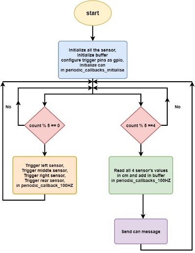
The sensor and bridge controller consists of sensor module that is responsible for object detection. Nimble uses ultrasonic sensors to achieve this task. As the name suggests, an ultrasonic sensor emits ultrasonic signal or beam from its head, and on encountering an object, returns back. This technique is better known as echolocation as we used sound signals to do so. The distance of the object is calculated based on the output and this ensures object detection. The distance measured is continuously passed on to driver node through can transceiver. The driver controller further processes the distance values of all the sensors on nimble and acts in accordance with the values to achieve obstacle avoidance.
Hardware Design
We have embedded 4 sensors on Nimble. We have arranged 3 LV-MaxSonar-EZ series Maxbotix ultrasonic sensors in the front section of the car; one at right, one at left and one in the center. The 4rth Ultrasonic sensor is placed at the rear end of the car. These sensors provide very short to long-range detection. It provides sonar range information from 6-inches out to 254-inches with 1-inch resolution.


A maxbotix sensor gives out 3 types of output- analog, RS232, and Pulse width. We have used analog output and hence, utilized on-board analog to digital converters- ADC2 (P0.25), ADC3 (P0.26), ADC4 (P1.30), and ADC5 (P1.31).
To trigger all the four ultrasonic sensors, we used P0.6, P0.7, P0.8 and P0.9 of SJTWO board. The analog output is converted to digital and transmitted to the driver controller. The converted adc distance data is passed to driver by Can transceiver. P0.0 is used as can tx and P0.1 as can rx on the sensor module
Software Design
<List the code modules that are being called periodically.>

Technical Challenges
< List of problems and their detailed resolutions>
Motor ECU
<Picture and link to Gitlab>
Hardware Design
Software Design
<List the code modules that are being called periodically.>
Technical Challenges
< List of problems and their detailed resolutions>
Geographical Controller
<Picture and link to Gitlab>
Hardware Design
Software Design
<List the code modules that are being called periodically.>
Technical Challenges
< List of problems and their detailed resolutions>
Communication Bridge Controller & LCD
<Picture and link to Gitlab>
Hardware Design
Software Design
<List the code modules that are being called periodically.>
Technical Challenges
< List of problems and their detailed resolutions>
Master Module
<Picture and link to Gitlab>
Hardware Design
Software Design
<List the code modules that are being called periodically.>
Technical Challenges
< List of problems and their detailed resolutions>
Mobile Application
<Picture and link to Gitlab>
Hardware Design
Software Design
<List the code modules that are being called periodically.>
Technical Challenges
< List of problems and their detailed resolutions>
Conclusion
<Organized summary of the project>
<What did you learn?> Nimble was a great opportunity to learn test-driven design strategies, which helped lower the amount of time troubleshooting issues. It also taught us much about using Git for version control. The project also gave us experience working with embedded systems technologies such as CAN bus communications, DBC files, GPIO, and signal debugging with BusMaster.
Project Video
Project Source Code
Gitlab Project Link - [6]
Advise for Future Students
<Bullet points and discussion>