S19: Hot Wheels
Contents
Project Title
Self-navigating RC car based on CAN communication.
Abstract
Embedded Systems are used to take real world input and covert it into the data that can be processed to monitor,control or obtain desired results. In this project , we aim to design and develop an autonomous self-driving RC car that navigates from the current location to the destination location that is selected through an Android application, avoiding all the obstacles in the path. The car comprises of 5 controllers communicating with each other over the CAN Bus, each having different functionality that helps the car to navigate to its destination successfully.
Introduction
The project was divided into 5 modules:
| Sensor Controller | This module detects obstacles in the driving path with the help of ultrasonic sensors. |
|---|---|
| Motor Controller | This controller drives the DC motor and Servo in the car and controls the speed of the car. |
| Geographical Controller | This module assists the car in navigating to a destination with the help of location details provided by GPS and the orientation(bearing and heading angle) provided by the compass. |
| Bluetooth Controller | The controller uses Bluetooth to communicate with an Android application on the Android phone. Destination coordinates are provided by this module. The Bluetooth module also displays important |
| Master Controller | This module will collect data from all modules and direct the motor module towards the destination. |
Team Members & Responsibilities
<Team Picture>
Gitlab Project Link - [1]
- Master Controller
- Kailash Chakravarty
- Sensor Controller
- Rishabh Sheth
- Motor Controller
- Kriti Hedau
- Tahir Rawn
- Geographical Controller
- Harmeen Joshi
- Nandini Shankar
- Communication Bridge Controller & Android Application
- Swanand Sapre
- Aquib Mulani
- Code Review & Commit Approvers
- Rishabh Sheth
- Nandini Shankar
- Kailash Chakravarty
Schedule
| Week# | Date | Task | Status | Completion Date |
|---|---|---|---|---|
| 1 | 02/12/19 |
|
|
|
| 2 | 02/17/19 |
|
|
|
| 3 | 02/26/19 |
|
|
|
| 4 | 03/05/19 |
|
|
|
| 5 | 03/12/19 |
|
|
|
| 6 | 03/19/19 |
|
|
|
| 7 | 03/26/19 |
|
|
|
| 8 | 04/02/19 |
|
|
|
| 9 | 04/09/19 |
|
|
|
| 10 | 04/16/19 |
|
|
|
| 11 | 04/23/19 |
|
|
|
| 12 | 04/30/19 |
|
|
|
| 13 | 05/07/19 |
|
|
|
| 14 | 05/14/19 |
|
|
|
| 15 | 05/22/19 |
|
|
|
Parts List & Cost
| Item# | Part Desciption | Vendor | Qty | Cost |
|---|---|---|---|---|
| 1 | RC Car | Traxxas | 1 | $250.00 |
| 2 | CAN Transceivers MCP2551-I/P | Microchip [2] | 8 | Free Samples |
| 3 | Graphics LCD module | 1 | From Preet | |
| 4 | Bluetooth(HC-05) | 1 | HiLetgo | $9.00 |
Printed Circuit Board
<Picture and information, including links to your PCB>
CAN Communication
<Talk about your message IDs or communication strategy, such as periodic transmission, MIA management etc.>
Hardware Design
<Show your CAN bus hardware design>
DBC File
Gitlab link to your DBC file [3]
VERSION "0.1.0"
BU_: MASTER SENSOR MOTORIO GEO APP
BO_ 220 MOTORIO_CMD: 4 MASTER
SG_ MOTORIO_CMD_Direction : 0|8@1+ (1,0) [0|2] "" MOTORIO
BO_ 210 ULTRA_CMD: 4 SENSOR
SG_ SENSOR_SONARS_FrontDistance : 0|8@1+ (1,0) [2|100] "" MASTER
BO_ 250 DISTANCE: 4 GEO
SG_ DISTANCE_FinalDistance : 0|16@1+ (0.1,0) [0|0] "" MASTER
BO_ 102 BLUETOOTH: 4 APP
SG_ DISTANCE_FinalDistance : 0|16@1+ (0.1,0) [0|0] "" MASTER
CM_ BU_ MASTER "The Master controller of the car";
CM_ BU_ MOTOR "The motor controller of the car";
CM_ BU_ SENSOR "The sensor controller of the car";
CM_ BU_ GEO "The Geo controller of the car";
CM_ BU_ APP "The Bluetooth/App controller of the car";
Sensor ECU
<Picture and link to Gitlab>
Motor Controller
Group Members
Design & Implementation
Hardware Design
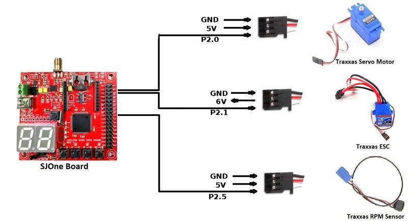
| Pin Number | Pin Function |
|---|---|
| P0.0 | CAN RX |
| P0.1 | CAN TX |
| P2.0 | Servo Motor |
| P2.1 | Electronic Speed Controller (ESC) |
| P2.5 | RPM Sensor |
Hardware Specifications
ESC and DC Motor
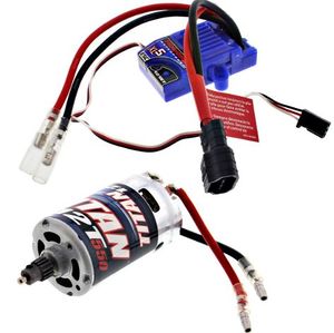
The Traxass Slash 4x4 has XL-5 Electronic Speed Controller (ESC) and Titan 12T DC Motor installed in it. The ESC is powered by LiPo Battery which further controls the DC motor. The ESC comes with the feature of calibrating the DC motor using the EZ set button that is present on ESC. It comes with three modes
- Sport mode (100% Forward, 100% Brakes, 100% Reverse)
- Training mode (100% Forward, 100% Brakes, No Reverse)
- Racing mode (50% Forward, 100% Brakes, 50% Reverse)
For our project we used Sport mode because we needed full capability of the motor for uphills and rough terrains. Also we used our ESC in Low-Voltage Detection activated mode. In order to know more about ESC profiles, Battery modes and how to calibrate them, refer to Traxxas official link here [4].
| Wires on (ESC) | Description | Wire Color Code |
|---|---|---|
| (+)ve | Positive Terminal | RED |
| (-)ve | Negative terminal | BLACK |
| Wires on (ESC) | Description | Wire Color Code |
|---|---|---|
| (+)ve | Connects to (+)ve of DC Motor | RED |
| (-)ve | Connects to (-)ve of DC Motor | BLACK |
| (+)ve | Connects to (+)ve of Battery | RED |
| (-)ve | Connects to (-)ve of Battery | BLACK |
| P2.0 (PWM1) | PWM Signal From SJOne | WHITE |
| VCC | 6 Volts (OUTPUT) | RED |
| GND | Ground | BLACK |
Servo Motor
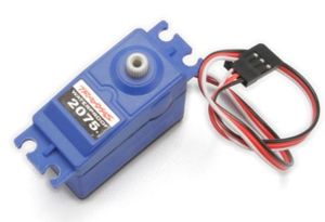
Servo Motor is responsible for steering the car. Traxxas Slash 4x4 has Servo Motor 2075 pre-installed in it. It controls the front two tires of the car.
| Pin No. (SJOne Board) | Function | Wire Color Code |
|---|---|---|
| P2.1 (PWM2) | PWM Signal | WHITE |
| VCC | 5V (INPUT) | RED |
| GND | Ground | BLACK |
RPM Sensor
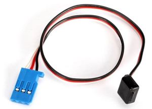
RPM sensor is used to calculate speed of the car. A magnet is placed inside the spur gear with the help of magnet holder and every time a tire completes one rotation, RPM sensor detects a pulse. RPM sensor it self is placed in the gear cover. In order get the RPM Sensor working, following Telemetry items from Traxxas are required
- Traxxas RPM Sensor 6522
- Traxxas Magnet Holder 6538
- Traxxas Gear Cover 6537
To install these, there is very detailed step by step tutorial by Steve Jones (Cstoneav) on Youtube which can be found here [5]
| Pin No. (SJOne Board) | Description | Wire Color Code |
|---|---|---|
| P2.5 (PWM6) | GPIO (INPUT) | WHITE |
| VCC | 5V (INPUT) | RED |
| GND | Ground | BLACK |
Hardware Interface
Software Design
Technical Challenges
Geographical Controller
<Picture and link to Gitlab>
Hardware Design
Software Design
<List the code modules that are being called periodically.>
Technical Challenges
<Bullet or Headings of a module>
Unreliable GPS lock
<Problem Summary> <Problem Resolution>
Communication Bridge Controller & LCD
User communicates with the car through the Communication Bridge Controller. This module consists of the LPC1758 communicating with the Android application on the phone via Bluetooth.The user selects the final destination on the google map to which the car should navigate, through an android application. The Android application also works as a display where it displays the recorded values of the ultrasonic sensors, the current latitude and longitude, the bearing angle, and the compass values for the car.
<Picture and link to Gitlab>
The Hardware and the Software details are given below:
Hardware Design
Software Design
<List the code modules that are being called periodically.>
get_gps_data(); compass_get_heading(); compass_get_heading()
Technical Challenges
<Bullet or Headings of a module>
Insane Bug
<Problem Summary> <Problem Resolution>
Master Module
<Picture and link to Gitlab>
Hardware Design
The Master controller only has the connections to the CAN bus apart from power supply. Below diagram describes the connections.
Software Design
- The Master control unit is the heart of the Self driving car as it takes all the critical decisions based on inputs it receives
from the other control units like App, Sensor, Geo and drives outputs which is the Motor control Unit.
- The Master control unit mainly performs Navigation of the car to the selected desination and Obstacle avoidance as and when they
come in the car's way.
- For navigation to the destination through numerous checkpoints, the bearing angle, heading angle and the distance to destination
is provided by the GEO control. The App control provides the start and stop command.
- The Sensor control provides the ultrasonic
sensor values of the 4 sensors
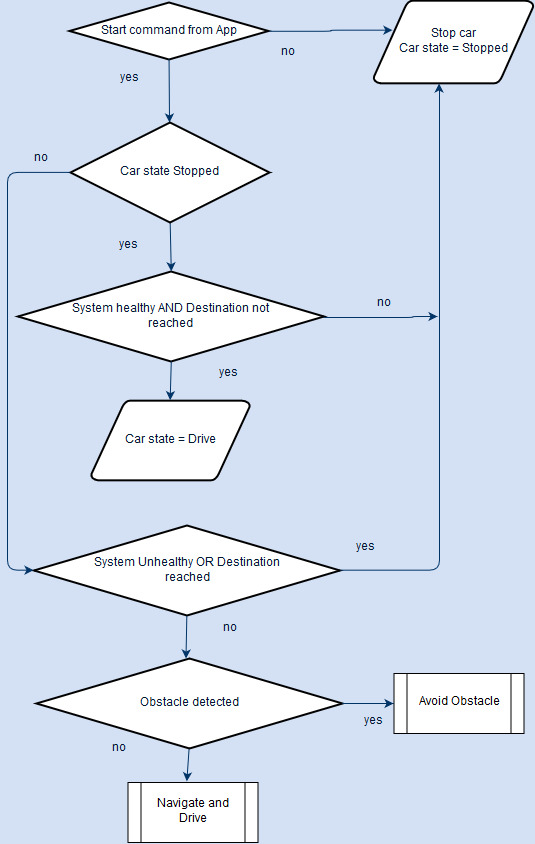
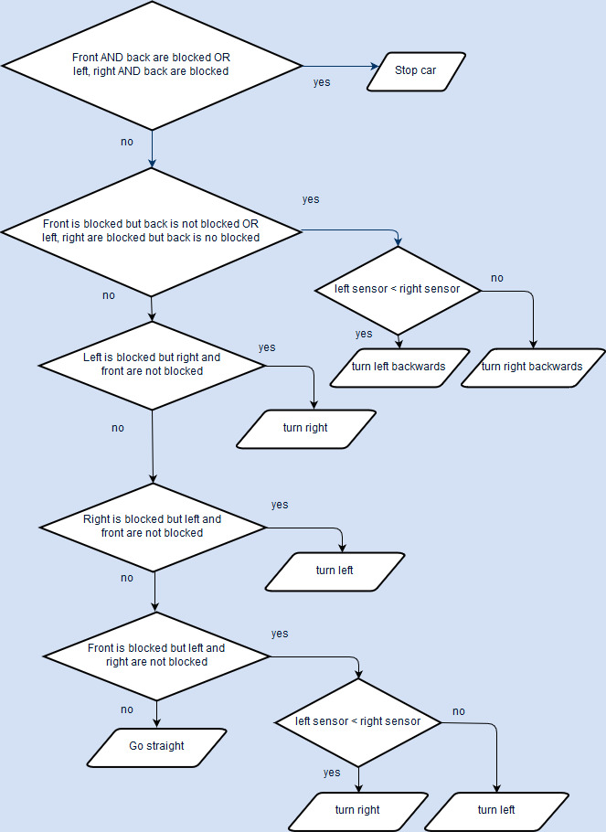
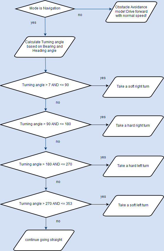
- The Master control unit algorithms - Navigation and Obstacle avoidance are run @25Hz. The detailed flowcharts are shown below.
Technical Challenges
<Bullet or Headings of a module>
Improper Unit Testing
Problem : It was tedious to tune the proximity thresholds for the 4 sensors for proper obstacle avoidance, because it involved changing them, build them, flash them and test again and again till we get fine tuned results. This was time and effort consuming.
Resolution : I placed a CAN debug message in the code to write directly into the threshold variables, via PCAN dongle and bussmaster whenever I want. So basically I change the thresholds anytime within seconds and immediately test.
Conclusion
<Organized summary of the project>
<What did you learn?>
Project Video
Project Source Code
Advise for Future Students
<Bullet points and discussion>
