S18: Team Nemesis(SJSU Cam)
Contents
SJSU Cam
Abstract
Our project is a digital camera implemented using the SJONE board. An image is captured using a camera and is then displayed on an LCD screen. An SD card is also used to store the output of the camera as the captured image. For navigating through various options on the LCD screen, a menu is created.
The camera is mounted on a 3D printed box which contains an LCD screen behind to display the image being captured by the camera.
Objectives & Introduction
The objective of this project was to learn how timing and buffer play an important role in capturing the pixels from the camera and displaying them on the LCD screen. The following objectives were set for the project:
1. Write a driver for camera ov2640, which has a better rate of capturing the image with the SJONE board and integrate it.
2. Store the output of the camera to SD card.
3. Write the driver for LCD (Adafruit 5' TFT) and integrate it by choosing the right resolution.
4. Read the image from the SD card and display on the screen.
5. Implement a menu for the options available on the digital camera.
Team Members & Responsibilities
- Chhavi Mehta
- Camera implementation, integration with SD card
- Deeksha Prakash Kankalale
- PCB Design, Camera driver implementation.
- Parth Gujar
- LCD Driver, 3D design.
- Sagar Kalathia
- LCD interfacing, implementing graphics library
- Saurabh Badenkal
- LCD Driver, Integration of camera and LCD and data pipelining.
Schedule
| Week# | Date | Task | Actual |
|---|---|---|---|
| 1 | 4/17 | 1. Placing order for the components required in the project. 2. Division of module development. |
Completed! Problems Encountered: Finding the right components after going through various datasheets. |
| 2 | 4/24 | 1. Making interface with LCD. 2. Drawing simple shapes. 3. Work on the overall design of the menu for LCD. |
Completed! Problems Encountered: Setting appropriate initial frequency for the LCD to light up. |
| 3 | 5/1 | 1. Interfacing the camera 2. Implementing menu class with sub-menus and items. 3. Designing hardware prototype for 3D printing. |
Completed! Problems Encountered: Not enough RAM for displaying more than 1 picture of size 100x100, Using interrupts for UART receive instead of normal function call. |
| 4 | 5/8 | 1. Design PCB and place order. 2. Integrating file explorer of the SD card onto LCD with GUI. 3. Capturing image from the camera, saving it on the SD card. |
Completed! Problems Encountered: Heavy resource utilization while saving and retrieving the file from SD card. |
| 5 | 5/15 | 1. Displaying the image on the LCD. 2. Integrating the modules together with the 3D case having the LCD on one side and SJONE and camera on the other with buttons. |
Completed! Problems Encountered: Resource constraints only allow a resolution of 320p. Extremely low frame rate due to SD read speeds. |
| 6 | 5/22 | 1. Final testing and debugging of the system as a whole. | Completed! Problems Encountered: PCB arrived late. |
Parts List & Cost
| Components | Model Number | Cost |
|---|---|---|
| SJONE board | LPC 1758 | 80$ |
| LCD | 5 inch TFT LCD screen | 32$ |
| LCD driver | RA8875 | 10$ |
| Camera | OV 2640 | 20$ |
| PCB | - | 50$ |
Design & Implementation
This design section outlines the hardware and software design of the project.
Hardware Design
The two main hardware components used in the project are discussed in detail below.
System block diagram:
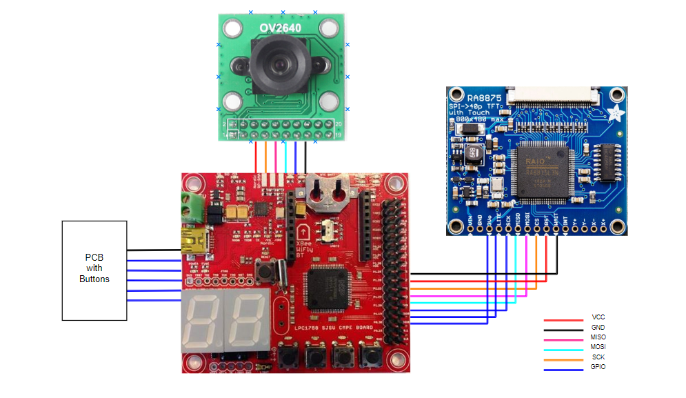

Figure : 5 inch LCD screen
LCD Screen:
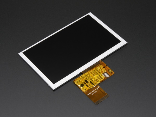

Figure : 5 inch LCD screen
This is a 5.0" TFT screen with 800x480 pixels. These screens are commonly seen in consumer electronics, such as miniature TV's, GPS's, handheld games car displays, etc. A 40-pin connector has 8 red, 8 green, and 8 blue parallel pins, for 24-bit color capability. The display is supposed to be constantly refreshed, at 60Hz, with a pixel clock. The backlight requires a constant-current mode boost converter that can go as high as 24V. Hence along with the display we use an RA8875 driver board.
LCD Driver :
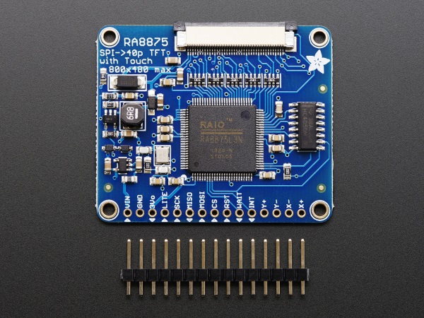

Figure : RA8875 Driver Board
The RA8875 is a powerful TFT driver chip, it has 768KB of RAM, so it can buffer the display (and depending on the screen size also have double overlaying).The RA8875 can also handle standard 4-wire over the SPI interface.
Camera:
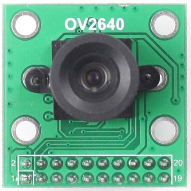

Figure : OV2640 camera
The OV2640 Camera Module is a small image sensor, works at low operating voltages. It provides all functions of a single chip of VGA camera and image processor. Through Serial Camera bus control, the sensor can output the whole frame, sampling at various resolution 8 bits of data. The product VGA image can reach up to a maximum of 30 frames per second. We can control the image quality, data format, and transmission mode. All the process of image processing functions can through the SCCB programming interface, including gamma curve, white balance, saturation, and chrome.
Camera Module Block Diagram :
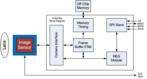

Figure : Block diagram of the camera module.
Hardware Interface
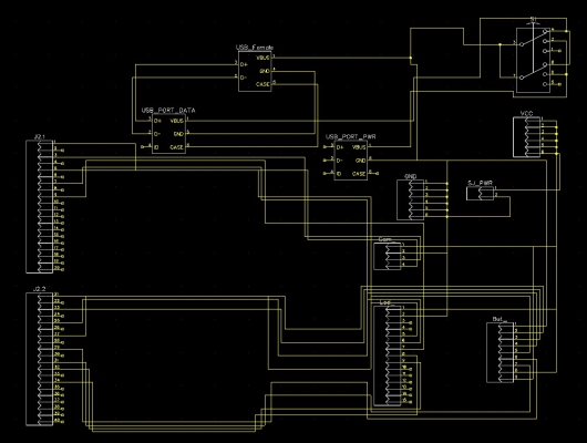
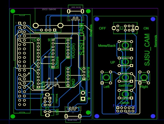
The SPI interface is done to both the camera and the driver board of the LCD display. The PCB design was done on Dip Trace, which is a CAD software for creating schematic diagrams and printed circuit boards.
Schematic:

PCB Design:

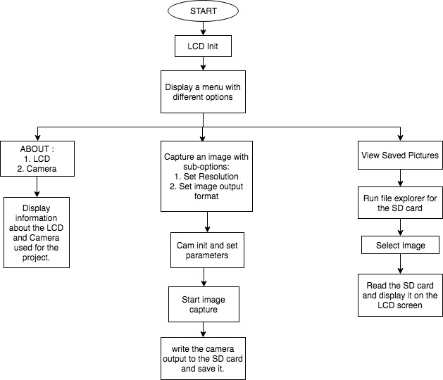
Software Design and Flowchart
The general flow of our project can be explained by the flowchart shown below:

Implementation
The camera is interfaced to the board where Image Sensor Configuration is done through I2C Protocol and Sending pixel data through SPI communication protocol. The raw pixels are read from the camera to the SJONE board. There are five buttons on the camera. One of them used to capture an image and store it on the SD card. The LCD screen is interfaced through SPI communication protocol. The raw pixels received from the camera are displayed on to the LCD screen.
MENU for the LCD
A menu was designed for the LCD screen using an LCD_MENU class. This class included functions like adding sub-menu, displaying them or loading previous ones. It helped in dynamically adding options for the innumerous camera settings like changing image resolution and format.The private members of this class are as shown:
   private:
   type myType;                         //to know if current object is itemType or menuType
   str myName;                          //name of this object
   LCD_MENU *ParentMenu;                //parent menu of current menu object
   LCD_MENU *CurrentMenu;               //reference to global CurrentMenuG
   VECTOR<Element> all_elements;        //to store all elements by Element .name .id and .type
   VECTOR<str> all_elements_name;       //to store all elements by name to use by Find function
   int highlighted;                     //to track currently highlighted sub-element
Similar to this class, a file_explorer class was implemented for navigating through the SD card files.
Algorithm:
In Terms of Pseudo Code & Algirthm, following is the methodology we followed which consists of API's and its functions. Design is mainly of two parts:
1) Design for LCD : LCD would continuously display menu on its right with different option. Menu driver is programmed dynamically using pointers & Function Pointer.
Various API & functions as follows:
- Add_Menu API, whenever gets called would add one more node to the linked list.
- Add_Submenu API would create Linked List inside that Node.
- "Navigate" API enables user to navigate through Menus. This API navigates pointer to different nodes and calling respective functions such as capture image or going inside sub_menu.
With this dynamic functionality, we can create menus as required inside which we can call the respective function to be performed according to submenu.
2) Design for SJOne & CAM : The controller has to Configure camera, receive data from the camera and send this to LCD as soon as it gets the data.
Function includes :
- Configuration of Camera Module by configuring different registers specified in datasheet & setting image format.
- To receive Data from Camera at 8 MHz through SPI. After receiving One Frame, it is sent to LCD via SPI. In both the case, Controller is Master and another device is a slave.
- To Store Image in SD card, whole frame is sent to SD card through SPI, and new text file with unique name is created and pixel values in that text file would be ascii values in matrix.
Testing & Technical Challenges
Problem 1: Making any camera work on SJOne can be little tricky. We found SJOne to be not so compatible with camera modules and have timing issue which leads to displaced images or sometimes no image at all.
Solution: After trying a number of cameras like OV7670 without fifo and VC0706 serial camera, we were able to solve the problem by using OV2640 camera with fifo which made capturing the image easier because the buffer saved the values rendering the timing issues.
Problem 2: The camera displayed two frames on the LCD screen for resolutions greater than 352x288. This was because the buffer size of the camera was less than LCD screen resolution.
Solution: This could be avoided by purchasing the right size of the LCD according to the camera buffer size.
Conclusion
We have successfully designed and implemented a digital camera with a number of features. This project has helped us gain insight knowledge of the implementation of FreeRTOS concepts like prioritizing tasks and using semaphore and mutex for SD card reading and writing. We learned to implement communication protocol drivers such as SPI. Working with images helped us go into deeper details of the SPI protocol as each byte had to be handled accurately. We have tried the PCB design on both Eagle and Dip Trace, we were able to complete the PCB design starting from schematic diagram to 3D imaging of the PCB. We were also able to learn the CAD design required for 3D printing.
Project Video
Here is a link to the demo of our Digital Camera.
Project Source Code
References
Acknowledgement
We would like to thank our professor, Preetpal Kang for designing such a course where learning was his guidance and consistent feedback. We would also like to thank the ISA team for their valuable inputs as per their own experience of the course when taken and their support and motivation at every phase of this project. There were some unsung, selfless classmates who helped us whenever necessary, whenever any immediate hardware was required or any other guidance needed in spite of being from the rival teams. We would like to thank each one of them who forgot their differences or considered the course and project as a competition to selflessly help us when in need.
References Used
[1] Preetpal Kang's lecture notes of CMPE 244, Computer Engineering, San Jose State University, Jan-May 2018.
[2] OV2640 Technical Description
[3] [ 5.0" LCD & Datasheet]