Difference between revisions of "S18: Spybot"
Proj user1 (talk | contribs) (→Hardware Interface) |
Proj user1 (talk | contribs) (→) |
||
| Line 324: | Line 324: | ||
== Testing & Technical Challenges == | == Testing & Technical Challenges == | ||
| − | === | + | === Noise Interference === |
* There was noise interference occurring when steering the car, which will somehow drive the car when the motor percentage is set to 0%. To fix the issue, the whole circuit was rewired and it fixed the issue. | * There was noise interference occurring when steering the car, which will somehow drive the car when the motor percentage is set to 0%. To fix the issue, the whole circuit was rewired and it fixed the issue. | ||
<p> </p> | <p> </p> | ||
Revision as of 00:41, 24 May 2018
Contents
Grading Criteria
- How well is Software & Hardware Design described?
- How well can this report be used to reproduce this project?
- Code Quality
- Overall Report Quality:
- Software Block Diagrams
- Hardware Block Diagrams
- Schematic Quality
- Quality of technical challenges and solutions adopted.
Project Title
Spybot
Abstract
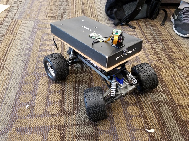
The team will develop a RC car driven remotely with an Android smartphone. The RC car will be equipped with a camera to provide real-time visual feedback to the smartphone. The camera will also be mounted on a servo to add the capability to change the camera angle. The SJOne will be used to drive the motor and servo of the car in addition to the camera’s servo. The Android smartphone will communicate with the SJOne using Bluetooth. The Android smartphone will be used to command the SJOne and drive the car and motorized camera. The RaspberryPi will stream visual data to the Android smartphone.
Objectives & Introduction
Team Members & Responsibilities
- YuYu Chen
- Android app & bluetooth communication
- Jason Tran
- PCB design & RC car firmware
- Sophia Quan
- Servo camera mount and camera integration
- Andrew Javier
- Camera integration
- Jeremy Chau
- Camera integration
Schedule
| Week# | Date | Task | Status |
|---|---|---|---|
| 1 | 04/15/2018 | Able to communicate with Bluetooth module on MCU by end of the week | Completed |
| 2 | 04/22/2018 | Start on Android application and have UI finished by end of week
Research possible ways to display live video feed in Android application |
Completed |
| 3 | 04/29/2018 | Establish Bluetooth communication with Android App and MCU
Start PCB design Start on motor and servo(s) controller Install MotionEyeOS and get familiar with the UI |
Completed |
| 4 | 05/06/2018 | Test Android app communication with RC car
Test RPi Camera with MotionEyeOS on multiple devices Get camera servo up and running by end of week |
Completed |
| 5 | 05/13/2018 | System Integration and testing | Completed |
| 6 | 05/20/2018 | System testing | Completed |
Parts List & Cost
| Quantity | Vendor | Item | Price |
|---|---|---|---|
| 1 | San Jose State University | SJ One Board | $80.00 |
| 1 | Adafruit | Raspberry Pi Zero W Camera Pack | $44.95 |
| 1 | Traxxas | Traxxas Stampede: Monster Truck | $199.95 |
| 1 | ITead | BTBee Pro | $12.50 |
| 1 | SparkFun | Servo Camera Mount | $6.50 |
| Total | $337.37 |
Design & Implementation
Hardware Design
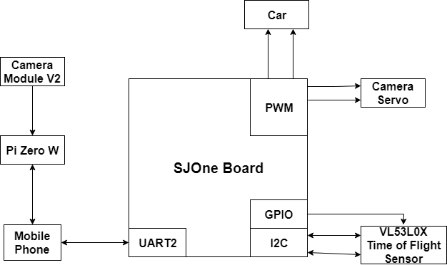
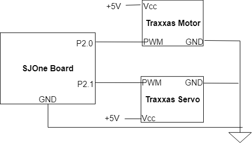
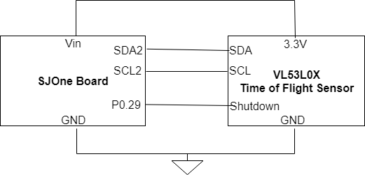
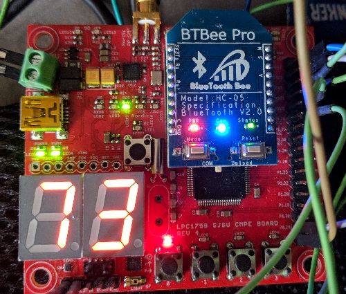
There are various connections to the SJOne Board in the project. To deal with the steering of the car, two different PWM pins are connected to the car: one for the motor and one for the servo. The camera servo also requires two connections to the PWM pins of the SJOne Board: one for the tilt and one for the horizontal movements. The VL53L0X time of flight sensor sends data through the I2C bus to the SJOne Board and requires a connection for the data and another for the clock. The sensor also connects to a general purpose output pin for its shutdown pin. To connect to the mobile phone, an XBEE Bluetooth module was placed on the board and it communicates with the microprocessor via UART. Finally, the mobile phone connects to the Raspberry Pi Zero W and camera through a hotspot connection.
Hardware Interface
Pin Connectivity Table
| Item | Pin Usage | Port.Pin | Direction | Peripheral | Peripheral Port |
|---|---|---|---|---|---|
| 1 | PWM | P2.0 | Output | SJ One Board | Car Motor |
| 2 | PWM | P2.1 | Output | SJ One Board | Car Servo |
| 3 | PWM | P2.2 | Output | SJ One Board | Camera Servo Tilt |
| 4 | PWM | P2.3 | Output | SJ One Board | Camera Servo Horizontal |
| 5 | I2C | SDA2 | Bidirectional | SJ One Board | VL53L0X SDA |
| 6 | I2C | SCL | Bidirectional | SJ One Board | VL53L0X SCL |
| 7 | GPIO | P0.29 | Output | SJ One Board | VL53L0X Shutdown |
| 8 | UART | - | Bidirectional | SJ One Board | XBEE Bluetooth |
PWM
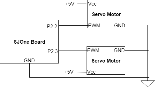
The camera mount consists of two different servo motors. The top servo motor is connected to Port 2.2 and controls the tilt and allows the camera to pan up and down. The other servo motor is connected to Port 2.3 and controls the horizontal range and allows the camera to look left and right. Additionally, the SJOne Board can not supply a sufficient amount of voltage to the servos to allow them to run so an external power source supplies 5 volts. The servos move based on a varying duty cycle supplied to the motor from the SJOne Board. The duty cycle in the 50 Hz PWM Period ranges from 1 ms to 2 ms. Based on the duration that the duty cycle is active, the servo will assume a position with a 1.5 ms duty cycle being the middle position.
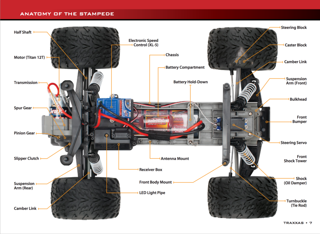
The Traxxas car is controlled by two motors: one to control the speed and one to control the direction. Both of these connections utilize the PWM functionality of the SJOne Board. The motor controls the speed which increases based on the duty cycle of the wave. The servo motor operates similarly to that of the camera mount and will turn to different positions based on the duty cycle of the wave.
I2C
The VL53L0X time of flight sensor connects to the SJOne Board through the I2C Bus. The SDA and SCL signals are connected to the SDA2 and SCL2 pins on the SJOne Board, respectively. In addition, the shutdown pin is connected to P0.29 which is used as an output with the GPIO functionality of the microprocessor to allow the sensor to reset.
UART
The bluetooth module is connected to the SJOne Board through the XBee WiFly BT insert area. It communicates to a mobile phone via Bluetooth and sends information to the microprocessor through the UART 2 communication protocol. The XBee module acts as a receiver to the board as the phone sends motor and servo controls through an application. The board also transmit the distance sensor data to the phone every half a second.
The bluetooth module receives data packets with the following detail
 bluetooth data motor% car_servo% camera_vertical% car_servo_left/right forward/backward
 camera_left/right camera_up/down camera_horizontal%
A bluetooth API was built in order to create an easy interface to set/get the parsed packet value.
Software Design
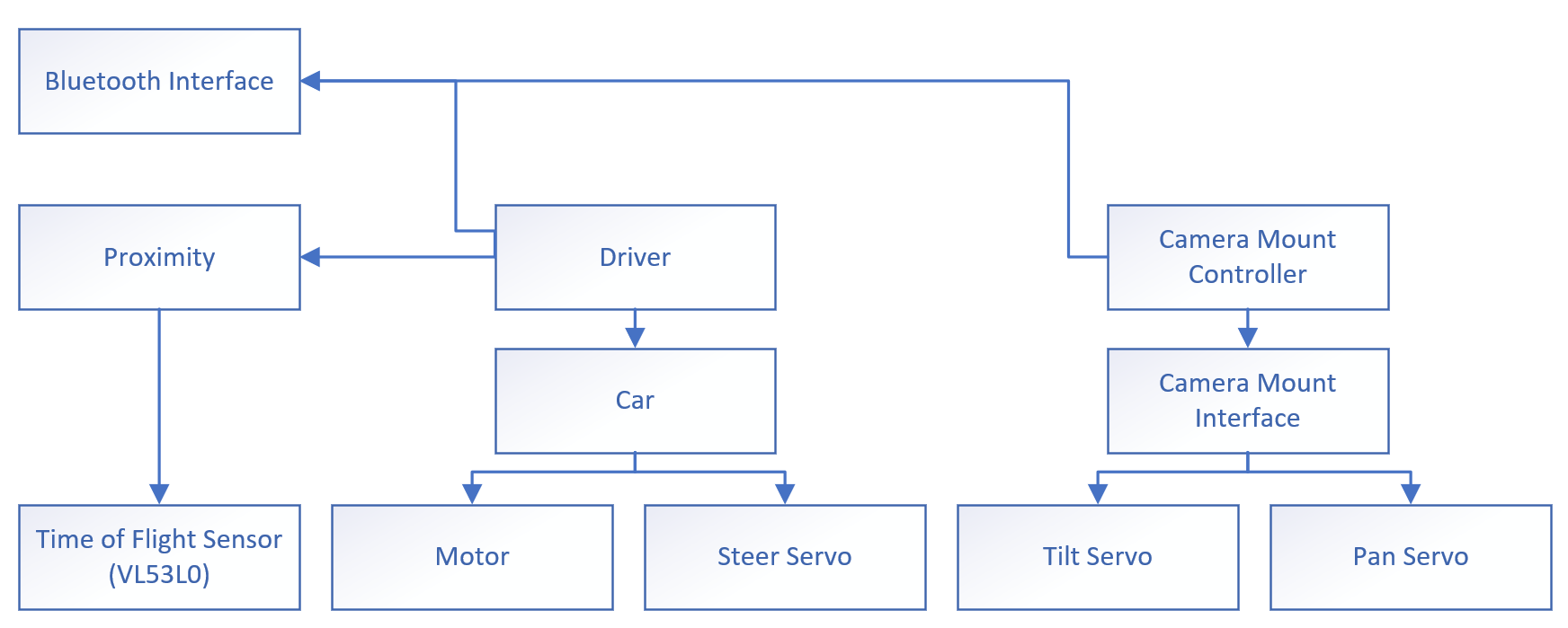
The firmware architecture consists of 4 application-specific modules: 1. Bluetooth interface 2. Driver 3. Proximity 4. Camera mount controller
The Bluetooth interface is responsible for communication between the firmware and the controller software (Android application). The bluetooth interface exposes the following functionality: drive the RC car and control the camera mount tilt/pan.
The driver is responsible for translating parameters acquired from the Bluetooth interface to control the car's servo and motor as commanded.
The proximity module is responsible for communicating with the time of flight sensor and provide an up-to-date frontal distance for proximity awareness. The driver uses the distance for collision avoidance by prohibiting the car from moving forward.
The camera mount controller is responsible for translating parameters acquired from the Bluetooth interface to control the camera mount's tilt servo and pan servo as commanded.
Implementation
This section includes implementation, but again, not the details, just the high level. For example, you can list the steps it takes to communicate over a sensor, or the steps needed to write a page of memory onto SPI Flash. You can include sub-sections for each of your component implementation.
Servo Motor
The servo motor is used as a camera mount for the Raspberry Pi camera. It uses a PWM signal and the percentage of how much the servo should pan or tilt is supplied by the Android application
Android Application
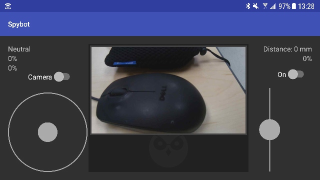
The main purpose of the Android application is to provide a simple user interface that allows the user to control the RC car via bluetooth. The user interface mimics what existing game consoles/controllers look like.
The Android app will provide:
- Autoconnect Bluetooth to RC car
- Steer the RC car left and right
- Drive the RC car forward and backwards
- Control servo tilt and pan orientation
The Android app will display:
- Live video feed from camera
- Current orientation of joystick
- Percentage of horizontal orientation
- Percentage of vertical orientation
- Speed of RC car in percentage
- Distance in millimeter from Time-of-Flight sensor
Software Design
High Level Architecture Design
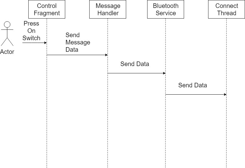
The application is able to send and receive to/from the RC car via Bluetooth. With its simple UI, it is easy to control the RC car. The RC car will not receive any data until the On switch is toggled. Once toggled, the RC car will receive the data packets if it is within the vicinity. The left joystick is used to steer the RC car left or right depending on the position within the joystick circle. It is also used to determine if the RC car will drive forward or backward.
To steer the camera, the Camera switch needs to be toggled. The left joystick is used to pan left and right, and tilt up and down if Camera is toggled.
The right joystick is control the speed of the RC car. The range is between 0% to 100%.
The webView in the middle of the app allows the user to stream live-feed video from the camera on the RC car.
Implementation
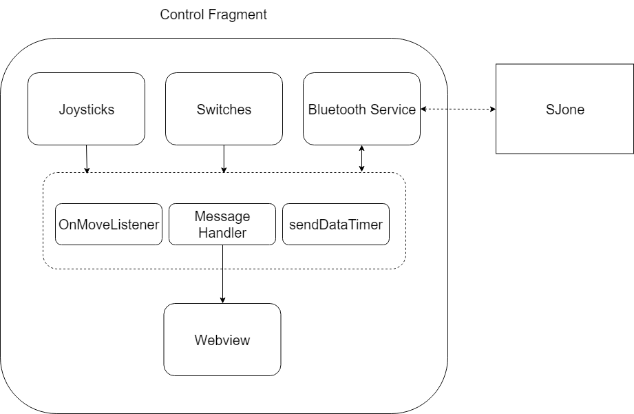
Control Fragment
The Control Fragment is the main fragment which contains all Views, such as textView, joystickView, and webView. This layer links the the message layer where different messages are handled. Joystick view is a custom view created by makowildcat. In order to download, the following needs to be added to the gradle script.
compile 'io.github.controlwear:virtualjoystick:1.9.2'
OnMoveListener is a callback function that is called every time the joystick position changes. The joysticks have a refresh rate of 50ms.
MessageHandler is an intermediate layer which handles all receiving and transmitting requests.
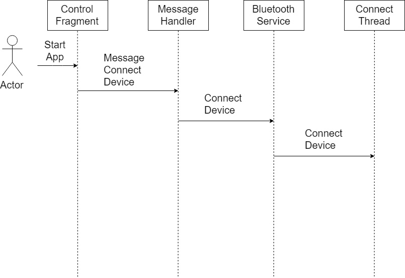
BluetoothService is the underlying layer after MessageHandler which assists with all high level Bluetooth functionality such as connect/disconnect and receiving/transmitting. It abstracts the detail of ConnectThread. In this layer, packets are also parsed so it can provide useful in the Fragment layer. This is also the layer where packets are built.
ConnectThread is the final layer which does the low level initialization such as UUID and opening/closing sockets. This layer handles all incoming and outgoing messages.
Use Cases
Auto Connect
When the app starts, auto connection to the RC car is initiated if it is in bluetooth range. It is able to auto connect by hardcoding the bluetooth MAC address in the app.
Sending Data
Packets of data is sent to the RC car periodically every 100ms when the On switch is toggled. The packet includes:
- motor drive percentage from 0% to 100%
- car steer percentage from 0% to 100%
- camera tilt percentage from 0% to 100%
- camera pan percentage from 0% to 100%
- flag to determine left or right steering of car
- flag to determine car to drive forward or backwards
- flag to determine camera tilt up or down
- flag to determine camera pan left or right
Camera pan/tilt percentage will only change when the Camera switch is toggled on. When toggled off, car steering percentage will change, along with its associated flags.
The car will default to move forward when the Camera switch is toggled off. The car will move backwards when the steering joystick is moved below the lower half and forward when moved above the center.
Testing & Technical Challenges
Noise Interference
- There was noise interference occurring when steering the car, which will somehow drive the car when the motor percentage is set to 0%. To fix the issue, the whole circuit was rewired and it fixed the issue.
Raspberry Pi Camera Ribbon
The ribbon used for the camera to communicate with the RPi is very sensitive. While testing out the camera and its settings, the video feed would cut out a lot when the ribbon was disturbed. There were times when the camera would not be detected at all. To remedy this issue, the connection was gently redone until the video feed returned.
Connecting to the Pi Zero W
Initially, the group wanted to have the phone to connect to the Raspberry Pi through Wi-Fi. However, when setting up the Pi to be a Wi-Fi host, the phones could not discover the Pi making communication impossible. Furthermore, it did not allow the Pi to initially boot up properly. To rectify this problem, the group decided to have the mobile phone with the application be a hotspot host. While this means that the Pi would have to be reconfigured every time it wants to connect to a new phone, the results would be consistent with the feed from the camera being able to broadcast to the host phone.
Conclusion
In conclusion, the project worked to the requirements we had set up at its inception. Throughout the project, there were a lot of errors encountered such as the noise which made steering the car difficult to the utilization of the Raspberry Pi. Despite all of this, we were able to complete the project in time and demo a car that can be viewed and steered through the application.
Project Video
Upload a video of your project and post the link here.
Project Source Code
References
Acknowledgement
- Preetpal Kang
- Khalil Estell
References Used
List any references used in project.
Appendix
You can list the references you used.
