S18: Audio Spectrum Analyzer with Graphics Display
Contents
Grading Criteria
- How well is Software & Hardware Design described?
- How well can this report be used to reproduce this project?
- Code Quality
- Overall Report Quality:
- Software Block Diagrams
- Hardware Block Diagrams
- Schematic Quality
- Quality of technical challenges and solutions adopted.
Project Title
Audio Spectrum Analyzer with Graphics Display
Abstract
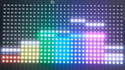
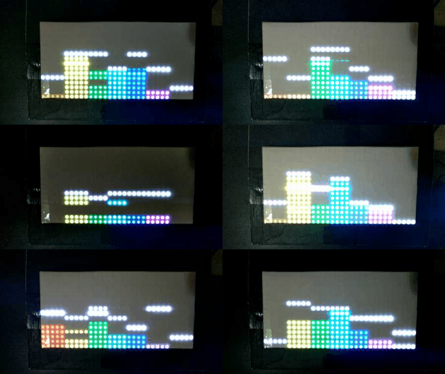
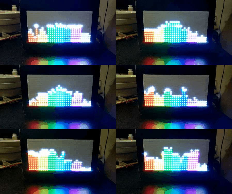
This porject is going to use an RGB LED-matrix to display graphics base on the MP3 audio frequencies, and with an MP3 decoder chip which will be used to connected to one of the SJOne board with MP3 files in its SD card to decode audio and send to DAC which is connected to our speakers. The user will be able to see graphics on the RGB LED matrix instantly while playing MP3 files, and have some control buttons to control the music like pause, resume, skip, and control matrix's display screen, modes, and rotation with different orientation.
Objectives & Introduction
Introduction
Our team split the project into four different parts: The audio decoder, the audio analyzer, the RGB LED Matrix, and the PCB design. Thus, two of our team members split the hardware and the software parts, some they worked together, some they worked individually. The other team member wanted to work on the PCB design and software and hardware of the LED matrix, he provided essential contribution to make audio analyzer working and try to work on other parts. The Equalizer part focuses on the conversion of audio input into an ADC output that can be parsed and create a data representation for the RGB LED Matrix. The RGB LED Matrix part is mainly focus on parsing the converted data and drive the RGB LEDs to display the dynamic frequencies of the signals.
Objectives
Follow proper engineering and testing practices to design and implement the following:
- Design equalizer PCB
- Interfacing audio decoder pin layout and system design
- Interfacing audio equalizer pin layout and system design
- Interfacing RGB LED matrix pin layout and system design
- Implement audio decoder driver
- Implement audio equalizer driver
- Implement RGB LED matrix driver
- Integrate equalizer and RGB LED matrix
- Test overall system and program
- Preparing whole project hardware design as a demo ready package
Team Members & Responsibilities
- Lorenzo Javier
- Audio Decoder Interfacing w/ SJOne Board (MP3 Driver)
- Graphic Equalizer Interfacing w/ Audio Decoder (Pin Layout/System Design)
- Jason Lin
- Graphic Equalizer Interfacing w/ SJOne Board (Audio Analyzer Driver)
- RGB LED Matrix Interfacing w/ SJOne Board (RGB LED Driver)
- All the nice to have functions (MP3 pause, resume, and skip / display modes, rotation, splash/pause/skip screen, and entertainment bar/dot and spinning)
- Made project container with cardboard box
- Bohan Liu
- PCB Design
- Design the basic schema for the Audio Decode Chip
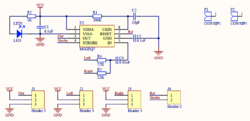
- Adding surrounding component to MSGEQ7 chip and make it connectable to other components
- Tested the connections of the basic schema
- Generate the connected PCB board layout
- Wired the PCB board layout
Schedule
| Week# | Ending date | Task | Actual |
|---|---|---|---|
| 1 | 4/15 |
|
Completed |
| 2 | 4/22 |
|
Completed |
| 3 | 4/30 |
|
Completed |
| 4 | 5/7 |
|
Completed |
| 5 | 5/14 |
|
Completed |
| 6 | 5/21 |
|
In progress |
Parts List & Cost
Give a simple list of the cost of your project broken down by components. Do not write long stories here.
| # | Name | Purchase Location | Description | Quantity | Cost |
|---|---|---|---|---|---|
| 1 | Audio Analyzer | Amazon DFROBOT | Graphic Equalizer Display Filter ‑ MSGEQ7 Breakout Board | 1 | $21.55 |
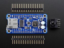
| 2 | Audio Decoder | Adafruit | VS1053 Audio Decoder Breakout Board w/ Breadboard-Friendly 3.5mm Stereo Headphone Jack | 1 | $24.95 |
| 3 | RGB LED Matrix (16x32) | Adafruit | RGB LED Matrix Panel (16x32) | 1 | $24.95 |
| 4 | Jumper Wires | Amazon | Variety of Male/Male, Male/Female, & Female/Female Breadboard Jumper Wires | 120 | $7.49 |
| 5 | Breadboard | Amazon | Breadboard - Small | 1 | $8.21 |
| 6 | SJOne Board | Social Ledge | LPC1758 Chipset | 2 | $160.00 |
| 7 | 5V 2.4A Portable Battery | Amazon | Portable Power Supply (5V 2.4A) | 1 | $10.99 |
Design & Implementation
This section will provide an overview of our design methodology for the MP3 audio decoder, audio analyzer graphic equalizer, and RGB LED matrix independently, and then will describe the integration of all components.
Hardware Design
MP3 Audio Decoder
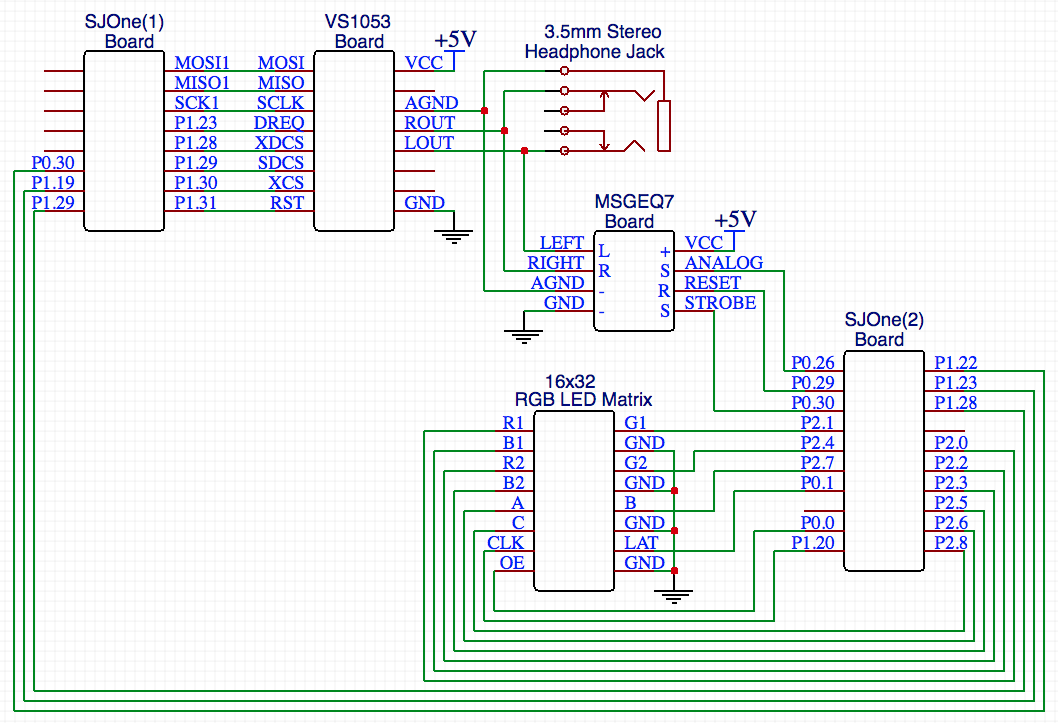
The VS1053 MP3 audio decoder breakout board connects to the SJOne board through the SPI protocol (MOSI, MISO, SCLK, XDCS) for sending/receiving data.
The other pins DREQ, XCS, SDCS, and RST are connected to the SJOne board pins as GPIO functionality.
The AGND, LOUT, and ROUT pins are split out between the 3.5mm stereo headphone jack and the audio analyzer breakout board.
Here is a description of the pin functionalities as follows:
- XCS -> a chip select pin for SCI operation (to control settings, i.e. volume)
- XDCS -> a chip select pin for SDI operation (to enable data transfer)
- RST -> a reset pin to perform a hard reset of previous data/settings
- DREQ -> a status pin to notify when the buffer is ready to receive more data (busy = 0, ready = 1)
- SDCS -> a chip select pin for enabling/disabling the MicroSD card slot
- AGND -> a common ground pin
- LOUT -> the analog left audio data pin
- ROUT -> the analog right audio data pin
The remaining pins are VCC (5V), and GND (Ground).
Graphic Equalizer
The Audio Analyzer breakout board features the MSGEQ7 graphic equalizer display filter. It splits the analog audio input into seven different frequency bands. The seven frequencies measured are as follows: 63Hz, 160Hz, 400Hz, 1kHz, 2.5kHz, 6.25kHz and 16kHz. It connects to the SJOne board through the ADC (ANALOG) protocol for reading the values of seven frequencies.
The other pins, RESET and STROBE, are connected to the SJOne board pins as GPIO functionality.
Here is a description of the pin functionalities as follows:
- ANALOG-> a chip select pin for Output analog signal (for ADC on SJOne board to read)
- RESET -> a chip select pin for Input GPIO signal (to get reset signal from SJOne GPIO)
- STROBE-> a chip select pin for Input GPIO signal (to be precisely controlled to read the analog outputs properly)
The remaining pins are VCC (5V), and GND (Ground).
RGB LED Matrix
The 16x32 RGB LED Matrix features as a display panel. It has two IDC connectors INPUT and OUTPUT on the back to connect multiple panels, but we only use one on this project. Its RGB data is separate in 1 and 2, 1 represent the upper half of the matrix, 2 represent the lower half. This matrix has a decoder which takes ABC as input to decode the corresponding row on both upper and lower half of the panel. Every color pin has a 32-bit shift register. With the clock single implement with the shift register, we can control every column of LED's color on each row.
The Latch signal is for indicate the end of the data line. It connects to the SJOne board through pins (R1, G1, B1, R2, G2, B2, A, B, C, CLK, LAT, OE) as GPIO functionality.
Here is a description of the pin functionalities as follows:
- R1 -> a chip select pin for Input GPIO signal (to control upper panel's R data)
- G1 -> a chip select pin for Input GPIO signal (to control upper panel's G data)
- B1 -> a chip select pin for Input GPIO signal (to control upper panel's B data)
- R2 -> a chip select pin for Input GPIO signal (to control lower panel's R data)
- G2 -> a chip select pin for Input GPIO signal (to control lower panel's G data)
- B2 -> a chip select pin for Input GPIO signal (to control lower panel's B data)
- A -> a chip select pin for Input GPIO signal (to select both upper and lower panel's row bit 2)
- B -> a chip select pin for Input GPIO signal (to select both upper and lower panel's row bit 1)
- C -> a chip select pin for Input GPIO signal (to select both upper and lower panel's row bit 0)
- CLK -> a chip select pin for Input GPIO signal (to get clock signal from SJOne board)
- LAT -> a chip select pin for Input GPIO signal (to get latch signal from SJOne GPIO)
- OE -> a chip select pin for Input GPIO signal (Output enable to cascade LED matrix)
The remaining pins are VCC (5V), and four GND (Ground).
Hardware Interface
In this section, you can describe how your hardware communicates, such as which BUSes used. You can discuss your driver implementation here, such that the Software Design section is isolated to talk about high level workings rather than inner working of your project.
MP3 Audio Decoder
The audio decoder was driven by the several pins mentioned from the Hardware Design section. It's main interface is SPI, which is great for transferring large amounts of bytes within a short amount of time. This is especially useful for live audio streaming, otherwise there would be many glitches, or a slow down of audio playback.
The SJOne's audio decoder driver included opening & reading the .mp3 files that were loaded onto the microSD card, which was inserted into the microSD card slot on the SJOne board, not the audio decoder board.
Graphic Equalizer
text
RGB LED Matrix
text
Software Design
Show your software design. For example, if you are designing an MP3 Player, show the tasks that you are using, and what they are doing at a high level. Do not show the details of the code. For example, do not show exact code, but you may show psuedocode and fragments of code. Keep in mind that you are showing DESIGN of your software, not the inner workings of it.
MP3 Audio Decoder
text
Graphic Equalizer
text
RGB LED Matrix
text
Implementation
This section includes implementation, but again, not the details, just the high level. For example, you can list the steps it takes to communicate over a sensor, or the steps needed to write a page of memory onto SPI Flash. You can include sub-sections for each of your component implementation.
Testing & Technical Challenges
Describe the challenges of your project. What advise would you give yourself or someone else if your project can be started from scratch again? Make a smooth transition to testing section and described what it took to test your project.
Include sub-sections that list out a problem and solution, such as:
MP3 Audio Decoder Challenges
Testing
We tested the audio decoder by loading .mp3 files onto a microSD card in the root directory, and then inserting it into the microSD card slot of the SJOne board. After writing the driver to read the microSD card and communicate between the MP3 audio decoder and the SJOne, we were able to hear audio through the audio jack. We tested multiple external audio devices, such as headphones, keychain speakers, and a large portable speaker to ensure the audio quality was consistent.
Pin Connections Challenge
The issue was that the MOSI and MISO connections were switched up. It took a while to see that these pins were connected incorrectly, but after some double checking, we made sure that the MOSI->MOSI pins and MISO<-MISO pins were properly attached to each other.
Graphic Equalizer Challenges
Reading the ADC values
In order to read the ADC values properly, generate the strobe with precise timing is required. If the timing isn't precise, the whole date of the frequency values will be messed up.
Testing
Because the MSGEQ7 chip is very sensitive to noise, we need to find out the lowest frequency it will read for every band. Even if there is no input, the MSGEQ7 chip can still read a small amount of values.
RGB LED Matrix Challenges
Matrix Array Controlling
The issue we had was trying to control one LED at a time in the matrix array. For example, following the pattern (row, column), the first LED index is (0, 0), and the last LED index is (15,31).
Algorithm of Display in LED Matrix
<Bug/issue name>
Color Variety
Due to the fact that the CPU Clock speed of the SJOne board isn't fast enough to let us smoothly control the RGB pins other than GPIO, so we can only set the LED's color in seven different colors.
Conclusion
Conclude your project here. You can recap your testing and problems. You should address the "so what" part here to indicate what you ultimately learnt from this project. How has this project increased your knowledge?
Project Video
Project Source Code
- [Audio Spectrum Analyzer with Graphics Display Source Code Link]
References
Acknowledgement
Any acknowledgement that you may wish to provide can be included here.
References Used
List any references used in project.
Appendix
You can list the references you used.
