S17: Sphero Droid
Contents
- 1 Grading Criteria
- 2 Project Title
- 3 Sphero Droid
- 4 Abstract
- 5 Objectives & Introduction
- 6 Schedule
- 7 Parts List & Cost
- 8 Design and Implementation
- 9 Ultrasonic Range Finders
- 10 Motors
- 11 GPS Module
- 12 SDCard
- 13 Bluetooth module and Android Application
- 14 Testing & Technical Challenges
- 15 Conclusion
- 16 References
Grading Criteria
- How well is Software & Hardware Design described?
- How well can this report be used to reproduce this project?
- Code Quality
- Overall Report Quality:
- Software Block Diagrams
- Hardware Block Diagrams
- Schematic Quality
- Quality of technical challenges and solutions adopted.
Project Title
Sphero Droid
Abstract
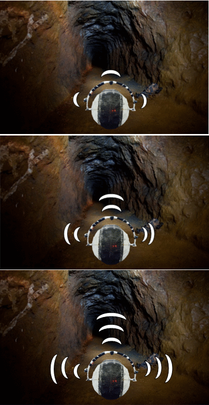
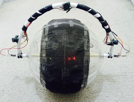
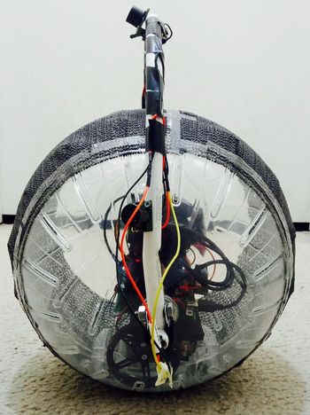
Robots are revolutionizing almost every industry, primarily in the sectors where human safety is at risk. In hazardous working conditions such as in the mining industry, the lack of knowledge about the geographic nature and the environmental conditions of the mine hinder the rescue operations. Autonomous robots are being employed to improve the plight of mine workers and rescue operators. The robotic vehicle can explore the inaccessible and unworkable mines and disaster-affected areas and send valuable information to the teams to assist in search and rescue operations. But traditional robots could be rendered useless if they are overturned or in terrains having staircases and ledges. Also, there is a possibility of failure of the electrical and mechanical components exposed to the harsh environmental conditions. An autonomous spherical robot is a better option since its shape offers better robustness and rigidity. The spherical robot will enclose all the components within it and will not have any wheels or legs on its exterior. This feature enables it to operate in any hazardous conditions since there will be very less chance for the components to get damaged by the surrounding environment. The spherical design allows it to easily maneuver in different types of terrain, be it stairs or corners, and have no risk of being overturned. These advantages enable the robot for many applications such as exploration and mapping of access routes, surveillance and rescue operations in uncomfortable working conditions.
Objectives & Introduction
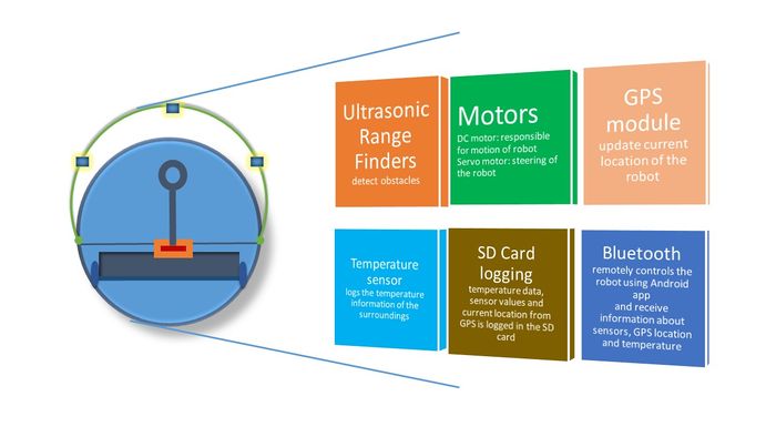
The objective of this project is to design an autonomous spherical robot with sensors, Global Positioning System (GPS) module, Bluetooth module and other control units interfaced to the microcontroller, which navigates its way to the destination avoiding obstacles. The temperature and the route followed by the robot can be logged on the SD card. These features enable the robot for many applications such as exploration and mapping of access routes, surveillance, and rescue operations in uncomfortable working conditions.
Team Members & Responsibilities
- Ultrasonic Range Finders
- Motors
- DC Motors
- Servo Motor
- GPS and Temerature Sensor
- SDCard
- Bluetooth module and Android Aplication
- PCB Designing
Schedule
| Week# | Start Date | End Date | Task | Status | Actual Completion Date | |
|---|---|---|---|---|---|---|
| 1 | 3/21 | 3/27 |
|
Done | 3/29 | |
| 2 | 3/28 | 4/3 |
|
Done | 4/9 | |
| 3 | 4/9 | 4/18 |
|
Done | 4/21 | |
| 4 | 4/18 | 4/25 |
|
Done | 4/28 | |
| 5 | 4/25 | 5/2 |
|
Done | 5/7 | |
| 6 | 5/2 | 5/9 |
|
In Progress | ||
| 7 | 5/9 | 5/20 |
|
Plan | ||
| 8 | 5/16 | 5/23 |
|
Plan |
Parts List & Cost
| Qty | Description | Manufacturer | Part Number | Cost | Links |
|---|---|---|---|---|---|
| 1 | SJ One Board [1] | Preet | SJ-one | $80 | http://www.socialledge.com/sjsu/index.php?title=SJ_One_Board |
| 2 | DC Motor | RobotShop | Pololu 4.5V, 80rpm Right Angle Plastic Gear Motor | $4.95 | http://www.robotshop.com/en/pololu-80rpm-right-angle-plastic-gear-motor.html |
| 1 | Servo Motor | Fry's electronics | Metal Gear Digital Servo Part No. LS-0009AF | $19.99 | http://www.frys.com/product/7027281 |
| 1 | Motor Driver | Fry's electronics | Motor Driver | $9.99 | http://www.frys.com/product/8353697 |
| 1 | GPS Logger | Spark fun Electronics | Venus638FLPx | $59.95 | https://www.sparkfun.com/products/10920 |
| 1 | Bluetooth Module | Amazon.com | HC-05 Bluetooth | $8.49 | https://www.amazon.com/dp/B01G9KSAF6?psc=1 |
| 3 | Ultrasonic sensor | Amazon.com | LV Maxsonar -EZ MB1010 | $74.85 | https://www.amazon.com/Maxbotix-MB1010-LV-MaxSonar-EZ1-Range-Finder/dp/B00A7YGVJI |
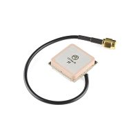
| 1 | Antenna GPS Embedded SMA | Spark fun Electronics | VTorch Datasheet | $11.95 | https://www.sparkfun.com/products/177 |
| 1 | PCB components | Amazon.com | (7805, 2 pin SPDT switch, 4004 diode, LD1117, Female pin header, male pin header, USB type B female jack, DC power jack, power supply module) | $72.00 | https://www.amazon.com/gp/product/B01LRXIJRY/ref=oh_aui_detailpage_o03_s02?ie=UTF8&psc=1 |
| 2 | Wheels | Amazon.com | 70 x 8mm Black Robot Wheels | $12.00 | https://www.amazon.com/gp/product/B00T3MQDHU/ref=oh_aui_detailpage_o08_s00?ie=UTF8&psc=1 |
| 2 | Bearing | Amazon.com | 2 Pcs 22mm Outside Dia Plastic Coated Ball | $7.93 | https://www.amazon.com/gp/product/B00HR5SJKE/ref=oh_aui_detailpage_o08_s01?ie=UTF8&psc=1 |
| 1 | Hollow spherical ball | Amazon.com | Giant Chinchilla Run-About 11-1/2-Inch Exercise Ball | $15.76 | https://www.amazon.com/gp/product/B0006IK0LA/ref=oh_aui_detailpage_o00_s00?ie=UTF8&psc=1 |
Design and Implementation
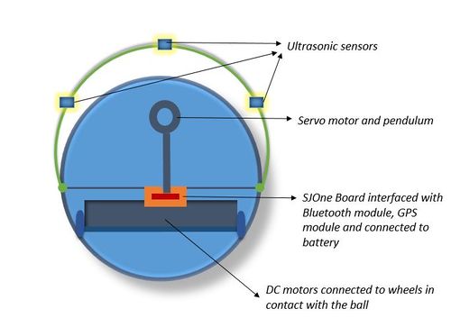
System Block diagram
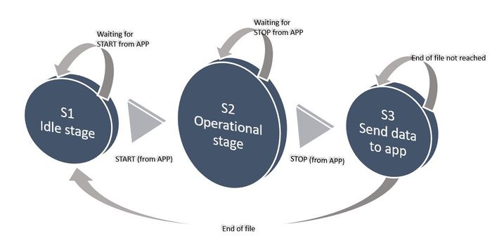
State Diagram
Ultrasonic Range Finders
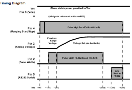
Hardware Design
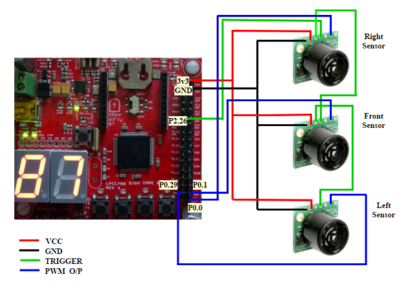
Hardware Interface
Software Design
Implementation
Motors
Hardware Design
Hardware Interface
- DC Motors
- Servo Motor
Software Design
Implementation
GPS Module
Hardware Design
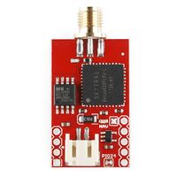
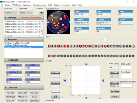
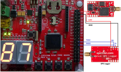
The GPS module used in our project is Venus GPS logger (Venus638FLPx) by Spark fun Electronics. This module is the successor of Venus634LPx and it has a higher update rate and can be configured to operate at an update rate of 20Hz.It can be connected to the PC using a serial to USB converter and configured with the help of a GPS viewer software by SkyTraq which has a GUI and is easy to use.This is handled by the software by sending appropriate commands to the GPS logger when any option is selected by the user.
By opening the correct COM port after connecting the GPS module to the PC, serial communication between the GPS module and PC can be established. The GPS logger works at a default baud rate of 9600bps but it can be configured to work at a baud rate of up to 115200bps. The changes in the configuration of the GPS module can be made permanent by writing the commands to the flash instead of the SRAM. The "Cold Start", "Warm Start" and "Hot Start" buttons on the bottom left corner of the screen define how fast a fix can be achieved by the GPS logger.
Hot Start: When a 3V battery is connected to the GPS module, it helps the GPS logger in saving information about the previous fix in its memory. This ensures that a fix is attained quickly when the system is switched on the next time. A warm start will happen if the module is switched on again before a specified amount of time, typically two hours.
Warm Start: As mentioned above if the module is switched on after about more than two hours then it will take a while for the module to attain a fix. It will take more time to attain a fix compared to the warm start, but is less than the time taken to attain a fix when the module is not fixed with a battery at all.
Cold Start: When a battery is not connected to the module at all then there is no information available about the previous fix and it would take a long time to attain a fix.
The output of the GPS module can be in NMEA format or SkyTraq Binary Message format. For sending the data from the GPS module to a controller it has to be configured to send data in the NMEA format. There are many message types in the NMEA format but for our project, the GGA type of NMEA output has been used which contains the time, position and fix related data for the GPS receiver.
The GGA message will have the following format
$GPGGA,hhmmss.sss,ddmm.mmmm,a,dddmm.m m m m,a,x,xx,x.x,x.x,M,,,,xxxx*hh<CR><LF>
1 2 3 4 5 6 7 8 9 10 11
             1   UTC of position in hhmmss.sss format
             2   Latitude in ddmm.mmmm
             3   Latitude hemisphere indicator, ‘N’ = North, ‘S’ = South
             4   Longitude in dddmm.mmmm
             5   Longitude hemisphere indicator, 'E' = East, 'W' = West
             6   GPS quality indicator
                    0: position fix unavailable
                    1: valid position fix, SPS mode
                    2: valid position fix, differential GPS mode
                    3: GPS PPS Mode, fix valid
                    4: Real Time Kinematic. System used in RTK mode with     fixed integers
                    5: Float RTK. Satellite system used in RTK mode. Floating integers
                    6: Estimated (dead reckoning) Mode
                    7: Manual Input Mode
                    8: Simulator Mode
             7   Number of satellites in use
             8   Horizontal dilution of precision
             9   mean sea level
             10  Differential reference station ID
             11  Checksum
Hardware Interface
Software Design
Implementation
SDCard
Hardware Design
Hardware Interface
Software Design
Implementation
Bluetooth module and Android Application
Hardware Design
Hardware Interface
Software Design
Implementation
PCB Designing
Hardware Design
|}
Hardware InterfaceSoftware DesignImplementation
Testing & Technical ChallengesDescribe the challenges of your project. What advise would you give yourself or someone else if your project can be started from scratch again? Make a smooth transition to testing section and described what it took to test your project. Include sub-sections that list out a problem and solution, such as: My Issue #1Discuss the issue and resolution. ConclusionConclude your project here. You can recap your testing and problems. You should address the "so what" part here to indicate what you ultimately learnt from this project. How has this project increased your knowledge? Project VideoUpload a video of your project and post the link here. Project Source CodeReferencesAcknowledgementAny acknowledgement that you may wish to provide can be included here. References UsedList any references used in project. AppendixYou can list the references you used. |
