S16: Motion Copy Bot

Contents
Motion Copy Bot

Abstract
Motion Copy Bot aims to copy the motion of the user. It can be used for day to day activities like in a supermarket. Instead of the user having to handle the cart, the cart can itself copy the motion of the user. Thus, freeing the user from the hassle of taking care of the cart along with the super market stuff. Robot mimics the direction of the user's movement. The Bot moves only when the user is in motion and stops as soon as the user halts. The user's wearable device communicates with the Bot and co-ordinates its movement. When the Bot detects an obstacle on its path it notifies the user by glowing a red LED and stops. In this project, we are using accelerometer and magnetometer sensor to replicate the motion of the user.
Objectives & Introduction
Project Objectives:
- Wireless Communication between user and Bot using Xbee.
- Determining direction and movement of the user with the help of Magnetometer and Accelerometer.
- Controlling the steering and throttle of the Bot.
- Obstacle Detection using Ultrasonic sensor.
Team Members & Responsibilities
- Ankita Singhal
- Wireless communication, Speed and Direction sensor module
- Manali Deshmukh
- Hardware Design and assembling, Motor Driver, Obstacle Avoidance
- Shaurya Jain
- Hardware Design and assembling, Motor Driver, Obstacle Avoidance
- Sukriti Choudhary
- Wireless communication, Speed and Direction sensor module
Schedule
| Week# | Date | Task | Actual | Status |
|---|---|---|---|---|
| 1 | 3/18/2016 |
|
|
Completed |
| 2 | 3/29/2016 |
|
|
Completed |
| 3 | 4/04/2016 |
|
|
Completed |
| 4 | 4/11/2016 |
|
|
Completed |
| 5 | 4/18/2016 |
|
|
Completed |
| 6 | 4/25/2016 |
|
|
Completed |
| 7 | 5/05/2016 |
|
|
Completed |
| 8 | 5/12/2016 |
|
|
Completed |
Parts List & Cost
| Item# | Part Description | Vendor | Qty | Cost |
|---|---|---|---|---|
| 1 | SJ One Board (LPC 1758) | From Preet | 2 | $160 |
| 2 | RC Car | Sheldon Hobbyist | 1 | $110 |
| 3 | Accelerometer/Magnetometer LSM303 | Adafruit | 2 | $40.00 |
| 4 | Wireless Module XBee S1 | From Preet | 2 | $0 |
| 5 | Motor Driver IC | From Amazon | 1 | $7 |
| 6 | Battery Pack | From eBay | 1 | $17.99 |
| 7 | Ultra Sonic Sensor | From Preet | 2 | $0 |
Design & Implementation
Block Diagram
-
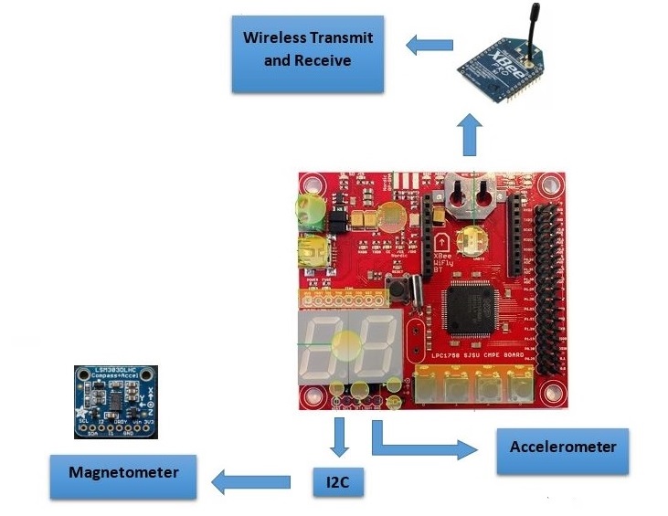 Master Block Diagram
 -
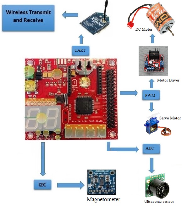 Bot Block Diagram


Hardware Design
Car Assembly
The car used in this project is a ready-to-run four-wheel drive RC car whose receiver is replaced with SjOne Board to control its motion. The assembly is made in such a way that the car is very durable and contains waterproof steering and throttle. The car uses a DC brushed motor which gets power from a 7.2 Volts 1300mAh six cells Nickel-Metal Hydride Battery. This motor is used for the forward and backward movement of the car. For the purpose of steering, the car uses a sg90 micro servo motor which works on a 50 Hz frequency with a maximum operating voltage of 4.8 Volts. The frame also has an adjustable suspension system for a shock proof motion.

Magnetometer

LSM303 is a triple-axis Accelerometer+Magnetometer (Compass) Board. It has a magnetic field full scale of ±1.3 / ±1.9 / ±2.5 / ±4.0 / ±4.7 /±5.6 / ±8.1 gauss. The system senses the magnetic field applied to it and generates a corresponding digital output. It includes an I2C serial bus interface that supports standard and fast mode 100 kHz and 400 kHz.
The structure of magnetometer is etched with microscopic coils. An excitation current is passed through the coils, and the Lorentz Force due to the magnetic field causes the structure to deflect. Once again the deflection is converted to an output voltage proportional to the strength of the magnetic field in that axis.
We use two magnetometers, one for obtaining the orientation of the user and the other for orientation of the Bot. The Bot aligns itself to match the user's orientation based on the error computed by comparison of the two orientations.
Accelerometer
The MMA8452Q is a smart low-power, three-axis, capacitive micro-machined accelerometer with 12 bits of resolution.The MMA8452Q has user selectable full scales of ±2g/±4g/±8g with high pass filtered data as well as non filtered data available real-time.
The internal structure of accelerometer are suspended by polysilicon springs which allow them to deflect when subject to acceleration in the X, Y and/or Z axis. Deflection causes a change in capacitance between fixed plates and plates attached to the suspended structure. This change in capacitance on each axis is converted to an output voltage proportional to the acceleration on that axis.
The movement of the user is sensed by the accelerometer sensor on the wearable device. This data is transmitted to the Bot, which in turn determines the start and stop motion of the Bot.
XBee Module
The XBee Modules meet IEEE 802.15.4 standards. The module operates within the ISM 2.4 GHz frequency band.The XBee®/XBee-PRO® RF Modules interface to a host device through a logic-level asynchronous serial port. Through its serial port, the module can communicate with any logic and voltage compatible UART. Devices that have a UART interface can connect directly to the pins of the RF module as shown in the figure. Data enters the module UART through the DI pin (pin 3) as an asynchronous serial signal.

Two Xbee Modules are being used in the project. One on the user side and the other on the Bot. Both act as transceivers and full duplex communication is established. The magnetometer and accelerometer data is transmitted over Xbee modules from user and Bot.
Ultrasonic Sensor
Ultrasonic sensors use high frequency sound to detect and localize objects in a variety of environments. Ultrasonic sensors transmits sound and measures the time interval between transmission and its reflection back from nearby objects. Based upon this time interval, it outputs a corresponding range reading.
LV-MaxSonar-EZ1 is an ultrasonic sensor IC that provides very short to long-range detection.It detects objects from 0-inches to 254-inches (6.45-meters) and provides sonar range information from 6-inches out to 254-inches with 1-inch resolution. It works on 2.5V to 5.5V and 2mA supply to generate a sound wave every 50ms. This sensor uses 3 protocols i.e. Pulse Width Modulatiom(PWM), ADC, serial communication to output the readings out of which we are using the ADC protocol.

Two ultrasonic sensors are used for this project which detects any obstacle that occurs in the path of the robot. As soon as the obstacle is detected, the robot stops.
Servo Motor

Servo Motor is controlled using PWM through wire controls. It can turn 90 degrees in either of the directions for a total of 180 degree movement. It is used to control the steering according to the commands given by the SJOne board. In this project, we are using SG90 Micro servo Motor which is tiny and lightweight with high output power.
Pin configuration for the servo motor is as follows:
| Sl. No | Servo Pin Color | Purpose |
|---|---|---|
| 1 | Brown | Ground |
| 2 | Red | VCC (max 4.8 Volts) |
| 3 | Yellow | PWM input to motor |
Below figure depicts the timing diagram of 1 cycle PWM for servo motor.

Sg90 Servo requires 50 Hz of frequency to drive its shaft. It means that the 1 PWM cycle is 20mS out of which 1 to 2 mS of duty cycle is required to drive the servo.
- 1mS duty cycle rotates the motor 90 degrees in anti-clockwise direction.
- 2mS duty cycle rotates the motor 90 degrees in clockwise direction.
- 1.5mS duty cycle brings the shaft at the center position.
DC Motor
The brushed DC motor is the classic motor which is useful for providing high speed and power in a relatively small package. It provides forward and backward movement of the robot. These movements are controlled by the SJOne board using PWM signals which are provided to the motor controller IC.

Motor Driver Controller
L298N is a high voltage, high current dual full-bridge driver designed to accept standard TTL logic levels and drive inductive loads like DC and stepping motors. Dual-channel H-bridge Motor Shield is composed of 2 discrete MOSFET H-bridge, designed to drive two DC motor with max current 7.2 A.
H Bridge configuration is used in electrical applications where the load needs to be driven in either direction. The H-bridge has four switching elements at the corners of the H and the motor forms the cross bar. A typical H-Bridge structure is shown below:

In the above figure, if only S1 and S4 switches are closed then the motor rotates clockwise and if S2 and S3 switches are closed then the motor rotates aniticlockwise. L298N is an H-Bridge motor driver IC uses MOSFET transistors for switching purposes. It controls the direction of two motors by driving the current in either polarity. It is controlled by PWM (Pulse Width Modulation).

The directions to the motor are given by the SJOne board through the input pins of L298N and the output is given to the motor through the output pins. The speed of the motor is controlled using PWM which is given to the Motor IC through the Enable pin. A power supply of 5V is given to the IC which drives the the output of the motor.
Hardware Interface
The pin configuration of both the Master and Slave is stated in table:

The block diagram along with the various pin connections are explained below


Software Design
Show your software design. For example, if you are designing an MP3 Player, show the tasks that you are using, and what they are doing at a high level. Do not show the details of the code. For example, do not show exact code, but you may show psuedocode and fragments of code. Keep in mind that you are showing DESIGN of your software, not the inner workings of it.

Movement Detect Algorithm (Master Controller)
As soon as the master is turned on, it checks if the user is moving or not. To determine the stop and forward motion of the Bot, the data obtained from the inbuilt acceleromoter of the SJ-One board is used. For determining the correct movement of the user, three acceleromoter values are collected from the sensor. A counter is set so as to make sure that the three values are obtained, before the start of comparison. After acquiring the three acclerometer values, absolute value of their difference is calculated.
i.e abs(sample1-sample2) and abs(sample2-sample3).
If the difference in any of the two mentioned cases is greater than 100, then the command for the Forward Throttle is transmitted to the Bot. If the difference is less than 100, then command to STOP is issued to the Bot. In this way whether or not the user is moving can be determined and corresponding command can be send to the Bot.
The following is the code for the Movement Detect Algorithm:
//Collect 3 consecutive data samples from accelerometer
if(numAccSample<3)

{

  zAccData[numAccSample] = AS.getZ();

}

else

{

  //if number of samples =3, start storing from 0 again

  numAccSample=0;

  zAccData[numAccSample] = AS.getZ();

}

numAccSample++;

//Compare the data sample values to determine user's movement

if((abs(zAccData[0]-zAccData[1])<=100)&&(abs(zAccData[1]-zAccData[2])<=100))

{

  botCommand = '2';                        //STOP

}

else

{

  botCommand = direction_command();	 //MOVE

}
Steering Controller Algorithm (Master Controller)
To understand the algorithm for controlling the steering, angles of rotation of the car and the master controller are compared. Following terms are used in this project:
- masterAngle = Magnetic angle of master controller board in degrees.
- slaveAngle = Magnetic angle of slave controller board in degrees.
- turningAngle = Saturation angle at which the car starts to turn in the direction of the master.
(Note: The turning angle in this project is taken as 25 degrees.)
angleDifference = masterAngle - slaveAngle

The following pseudo code shows the implementation of the above table:
if((abs(angleDifference) < turningAngle) || (abs(angleDifference) > (360 - turningAngle)))

{

	//Command Bot to move Straight

}

else if(((angleDifference < 0) && (abs(angleDifference) < 180)) || ((angleDifference > 0) && (abs(angleDifference) > 180)))

{

	//Command Bot to steer Left

}

else if(((angleDifference < 0) && (abs(angleDifference) > 180)) || ((angleDifference > 0) && (abs(angleDifference) < 180)))

{

	//Command Bot to steer Right

}

Slave side algorithm
The flow of the software starts from the slave side. The first step at the slave side is to perform the when alignment calibration of the servo motor. The servo motor needs 7.5% of the duty cycle to align the shaft in the center position. However, the wheel’s position might not be proper when the shaft is at center due to the non-alignment of the mechanical parts of the car body. So, to bring the wheels in position, wheel alignment is done at the starting of the code.
As soon as the, the master board is turned on, the magnetometer at the slave side starts to compute the magnetic angle at which the car is positioned. The slave angle found by the magnetometer ranges from 0 to 360 degrees. This angle is then scaled to the range of 0 to 255 so as to be transmitted by the XBee module in the form of a single byte. This range is named as “Rotation Character”. This rotation factor is then transmitted to the master board controller via XBee Module. The rotation character is converted back to the rotation angle range of 0 to 360 at the master receiver side after the character has been received.
In the meantime, the master computes the magnetic angle of the car. The master angle and the slave angle are then compared, and the desired direction for the car is calculated. The resulting direction is transmitted back to the slave in the form a character and the car moves in the desired direction. The car wheels turns in the best possible direction computed by the master controller. The slave side controller also check the readings of two ultra-sonic sensors to detect an obstacle. Ultra-sonic sensors are connected to the ADC input of the board which operates from 0 to 3.3 Volts. In this project, 2 ultrasonic sensors are used to increase the efficiency. Whenever, the car detects an obstacle in its path the ultra-sonic sensors gets triggered and the car is stopped. A red LED also glows to notify the presence of an obstacle.

DC Motor Controller Algorithm (Slave Controller)
The L298N motor controller IC used for this project require three logical inputs i.e. one PWM signal to control the speed and two GPIO inputs to control the direction of the rotation. Two GPIO Ports (i.e. P1.19 and P1.90) of the LPC1758 microprocessor are used.
motor.dc is an 8 bit char variable member of a global struct i.e. botDriver.
- Motor rotates in clockwise direction, If bit 0 = 1 and bit 1 = 0 of motor.dc
- Motor rotates in anti-clockwise direction, If bit 0 = 0 and bit 1 = 0 of motor.dc
- Motor stops moving, If bit 0 = 0 and bit 1 = 0 of motor.dc
Pseudo code for controlling the dc motor is as shown below:
PWM dc(PWM::pwm2, 1000); //enable PIN
dc.set(speed);
if((motor.dc & (1<<0)) && !(motor.dc & (1<<1))) //forward
{
   LPC_GPIO1 -> FIOSET = (1<<19); // input 1
   LPC_GPIO1 -> FIOCLR = (1<<20); // input 2
}
if(!(motor.dc & (1<<0)) && (motor.dc & (1<<1))) //backward
{
   LPC_GPIO1 -> FIOCLR = (1<<19);// input 1
   LPC_GPIO1 -> FIOSET = (1<<20);// input 2
}
if(!(motor.dc & (1<<0)) && !(motor.dc & (1<<1))) //stop
{
   LPC_GPIO1 -> FIOCLR = (1<<19); // input 1
   LPC_GPIO1 -> FIOCLR = (1<<20); // input 2
}
Servo Motor Controller Algorithm (Slave Controller)
The servo motor used in this project is a micro servo that operates on 50 Hz frequency and 5% to 10% duty cycle. Servo remains at the center when duty cycle is 7.5%. Servo moves clockwise when duty cycle is 10% and moves anti-clockwise when duty cycle is 5%. To avoid hardware wheel alignment problem, a Wheel Alignment Factor is taken whose value is made fixed according to the bot assembly.
motor.servo is an 8 bit char variable member of a global struct i.e. botDriver.
- Servo moves the steering towards left, If bit 0 = 1 and bit 1 = 0 of motor.servo
- Servo moves the steering towards right, If bit 0 = 0 and bit 1 = 0 of motor.servo
- Servo brings the steering to the center, If bit 0 = 0 and bit 1 = 0 of motor.servo
Pseudo code for controlling the dc motor is as shown below:
wheelAlignmentFactor = 0.45;
PWM servo(PWM::pwm1, 50);
if(!(motor.servo & (1<<0)) && !(motor.servo & (1<<1))) //Center aligned
{
   servo.set(7.5 - wheelAlignmentFactor); //center wheel alignment
}
else if((motor.servo & (1<<0)) && !(motor.servo & (1<<1))) //Steer left
{
   servo.set(10.0); // left alignment
}
else if(!(motor.servo & (1<<0)) && (motor.servo & (1<<1))) //Steer right
{
   servo.set(5.0); //right alignment
}
Obstacle Detection Algorithm (Slave Controller)
This project uses two ultrasonic motors that generates an ADC input of 0 to 3.3V operating voltage whenever there is an obstacle in front of the bot. The pseudo code is shown as below:
int adc4 = adc0_get_reading(4);
int adc5 = adc0_get_reading(5);
if(adc4 < 300 && adc5 < 300)
{
   obstacleDetected = true;
   stop();
}
else
{
   obstacleDetected = false;
}
Implementation
Actual Implementation Images:


Technical Challenges
Electro-Magnetic Interference:
Issue:
We get incorrect magnetometer reading due to electromagnetic interference in the surroundings. Due to this interference, the bot deviates from its desired path. The problem is more persistent in the areas where there are more electrical components and wiring.
At the initial stage of the development of this project, we placed the magnetometer sensor just above the chassis of the RC car where the DC motor and Servo motor are located. After several test runs, we found out that the magnetometer readings were anomalous. The reason behind this was the magnetic fields from the magnet bars inside the motors.
Solution:
To reduce the electro-magnetic interference down to a negligible value, the sensor was fixed high above the chassis with the help of a wooden support.
Wheel Alignment:
Issue:
The default hardware assembly of the RC Car had a wheel alignment issue. With the forward movement command, the car deflected from its straight path. We later found that the front wheels were slightly misaligned from the center. Due to this issue, the car took unnecessary turns to synchronize with the master’s direction.
Solution:
The front wheels were adjusted by setting an initial value of duty cycle. With this offset, the servo motor aligned the wheels in the center. Below is the snapshot that depicts the issue and the solution in a pictorial way:

Testing
The following tests were performed to verify the successful implementation of the project:
1. Data transfer between the two SJOne boards using the XBee module.
2. Synchronization between the user's direction with the steering of the servo motor.
3. The car halted when the master board stopped moving and the car resumed when the master movement was observed.
4. The Bot halted when an obstacle was detected and the led was turned on.
5. The entire implementation was verified by checking if all the movements of the user are getting copied by the Bot.
Thus it was verified that the implementation is working successfully.
Conclusion
In this project, our robot was successfully able to copy the motion and directions of the user using accelerometer and magnetometer sensor values. These values were sent to the user through XBee and were used to drive the DC motor and servo motor in the direction of the user. In this way, the robot was able to copy the movement of the user.
Through this implementation, we learnt the following:
- Calibration of the magnetometer and accelerometer sensor values
- Interface of XBee module using UART protocol with the SJOne board for communicating the sensor values to the user end
- Interfacing DC and servo motors with the SJOne board
- Use of I2C bus for acquiring the values of the sensors
- Use of PWM to control the speed of the DC motor and servo motor
- Interface of ultrasonic sensors with the board using ADC
- Use of FreeRTOS features like the semaphores and the interrupts
Applications
The Motion Copy Bot can find its applications in day to day life.
Supermarket: We usually have to push our carts everywhere while shopping which becomes tedious during shopping. The Motion Copy Bot can be used as a shopping cart that will follow or copy the motion of the user. The user will not have to drag the cart everywhere. Thus, making shopping easy and fun.
Defense Applications: It can also be used in defense applications like remote surveillance where the Bot can be sent to remote places which are not reachable by a human.
Project Video
Project Source Code
References
Acknowledgement
We would like to thank Preet for explaining the various Embedded Software concepts. The understanding of these concepts helped us in successful implementation of this project. Also, this project has helped us put into practice whatever we learned in the class.
References Used
https://cdn-shop.adafruit.com/datasheets/LSM303DLHC.PDF
http://www.nxp.com/files/sensors/doc/data_sheet/MMA8452Q.pdf
https://www.sparkfun.com/datasheets/Wireless/Zigbee/XBee-Datasheet.pdf
https://www.sparkfun.com/datasheets/Components/General/L298N.pdf
http://www.maxbotix.com/documents/LV-MaxSonar-EZ_Datasheet.pdf
https://learn.adafruit.com/lsm303-accelerometer-slash-compass-breakout/overview