S16: Motion Copy Bot

Contents
Grading Criteria
- How well is Software & Hardware Design described?
- How well can this report be used to reproduce this project?
- Code Quality
- Overall Report Quality:
- Software Block Diagrams
- Hardware Block Diagrams
- Schematic Quality
- Quality of technical challenges and solutions adopted.
Motion Copy Bot
Abstract
Motion Copy Bot aims to copy the motion of the user. Robot mimics the direction of the user's movement. The Bot moves only when the user is in motion and stops as soon as the user halts. The user's wearable device communicates with the Bot and co-ordinates its movement. When the Bot detects an obstacle on its path it notifies the user and stops. Upon this alert, the user determines the alternate path for the Bot.
Objectives & Introduction
Project Objectives:
- Wireless Communication between user and Bot using Xbee.
- Determining direction and movement of the user with the help of Magnetometer and Accelerometer.
- Controlling the steering and throttle of the Bot.
- Obstacle Detection using Ultrasonic sensor.
Team Members & Responsibilities
- Ankita Singhal
- Wireless communication, Speed and Direction sensor module
- Manali Deshmukh
- Hardware Design and assembling, Motor Driver, Obstacle Avoidance
- Shaurya Jain
- Hardware Design and assembling, Motor Driver, Obstacle Avoidance
- Sukriti Choudhary
- Wireless communication, Speed and Direction sensor module
Schedule
| Week# | Date | Task | Actual | Status |
|---|---|---|---|---|
| 1 | 3/18/2016 |
|
|
Completed |
| 2 | 3/29/2016 |
|
|
Completed |
| 3 | 4/04/2016 |
|
|
Completed |
| 4 | 4/11/2016 |
|
|
Completed |
| 5 | 4/18/2016 |
|
|
Completed |
| 6 | 4/25/2016 |
|
|
Completed |
| 7 | 5/05/2016 |
|
|
Completed |
| 8 | 5/12/2016 |
|
In Progress |
Parts List & Cost
| Item# | Part Description | Vendor | Qty | Cost |
|---|---|---|---|---|
| 1 | SJ One Board (LPC 1758) | From Preet | 2 | $160 |
| 2 | RC Car | Sheldon Hobbyist | 1 | $110 |
| 3 | Accelerometer/Magnetometer LSM303 | Adafruit | 2 | $40.00 |
| 4 | Wireless Module XBee S1 | From Preet | 2 | $0 |
| 5 | Motor Driver IC | From Amazon | 1 | $7 |
| 6 | Battery Pack | From eBay | 1 | $17.99 |
| 7 | Ultra Sonic Sensor | From Preet | 2 | $0 |
Design & Implementation
-
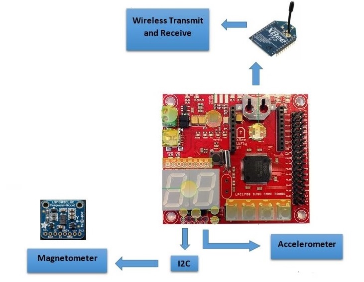 Master Block Diagram
 -
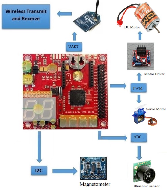 Bot Block Diagram


Hardware Design
Car Assembly
// add two lines about car framework shaurya

Magnetometer

LSM303 is a triple-axis Accelerometer+Magnetometer (Compass) Board. It has a magnetic field full scale of ±1.3 / ±1.9 / ±2.5 / ±4.0 / ±4.7 /±5.6 / ±8.1 gauss. The system senses the magnetic field applied to it and generates a corresponding digital output. It includes an I2C serial bus interface that supports standard and fast mode 100 kHz and 400 kHz.
The structure of magnetometer is etched with microscopic coils. An excitation current is passed through the coils, and the Lorentz Force due to the magnetic field causes the structure to deflect. Once again the deflection is converted to an output voltage proportional to the strength of the magnetic field in that axis.
We use two magnetometers, one for obtaining the orientation of the user and the other for orientation of the Bot. The Bot aligns itself to match the user's orientation based on the error computed by comparison of the two orientations.
Accelerometer
The MMA8452Q is a smart low-power, three-axis, capacitive micro-machined accelerometer with 12 bits of resolution.The MMA8452Q has user selectable full scales of ±2g/±4g/±8g with high pass filtered data as well as non filtered data available real-time.
The internal structure of accelerometer are suspended by polysilicon springs which allow them to deflect when subject to acceleration in the X, Y and/or Z axis. Deflection causes a change in capacitance between fixed plates and plates attached to the suspended structure. This change in capacitance on each axis is converted to an output voltage proportional to the acceleration on that axis.
The movement of the user is sensed by the accelerometer sensor on the wearable device. This data is transmitted to the Bot, which in turn determines the start and stop motion of the Bot.
XBee Module
The XBee Modules meet IEEE 802.15.4 standards. The module operates within the ISM 2.4 GHz frequency band.The XBee®/XBee-PRO® RF Modules interface to a host device through a logic-level asynchronous serial port. Through its serial port, the module can communicate with any logic and voltage compatible UART. Devices that have a UART interface can connect directly to the pins of the RF module as shown in the figure. Data enters the module UART through the DI pin (pin 3) as an asynchronous serial signal.

Two Xbee Modules are being used in the project. One on the user side and the other on the Bot. Both act as transceivers and full duplex communication is established. The magnetometer and accelerometer data is transmitted over Xbee modules from user and Bot.
Ultrasonic Sensor
Ultrasonic sensors use high frequency sound to detect and localize objects in a variety of environments. Ultrasonic sensors transmits sound and measures the time interval between transmission and its reflection back from nearby objects. Based upon this time interval, it outputs a corresponding range reading.
LV-MaxSonar-EZ1 is an ultrasonic sensor IC that provides very short to long-range detection.It detects objects from 0-inches to 254-inches (6.45-meters) and provides sonar range information from 6-inches out to 254-inches with 1-inch resolution. It works on 2.5V to 5.5V and 2mA supply to generate a sound wave every 50ms. This sensor uses 3 protocols i.e. Pulse Width Modulatiom(PWM), ADC, serial communication to output the readings out of which we are using the ADC protocol.

Two ultrasonic sensors are used for this project which detects any obstacle that occurs in the path of the robot. As soon as the obstacle is detected, the robot stops.
Servo Motor
Servo Motor is controlled using PWM through wire controls. It can turn 90 degrees in either of the directions for a total of 180 degree movement. It is used to control the steering according to the commands given by the SJOne board. In this project, we are using SG90 Micro servo Motor which is tiny and lightweight with high output power.

Pin configuration for the servo motor is as follows:
| Sl. No | Servo Pin Color | Purpose |
|---|---|---|
| 1 | Brown | Ground |
| 2 | Red | VCC (max 4.8 Volts) |
| 3 | Yellow | PWM input to motor |
Below figure depicts the timing diagram of 1 cycle PWM for servo motor.

Sg90 Servo requires 50 Hz of frequency to drive its shaft. It means that the 1 PWM cycle is 20mS out of which 1 to 2 mS of duty cycle is required to drive the servo.
1mS duty cycle rotates the motor 90 degrees in anti-clockwise direction.
2mS duty cycle rotates the motor 90 degrees in clockwise direction.
1.5mS duty cycle brings the shaft at the center position.
DC Motor
The brushed DC motor is the classic motor which is useful for providing high speed and power in a relatively small package. It provides forward and backward movement of the robot. These movements are controlled by the SJOne board using PWM signals which are provided to the motor controller IC.

Motor Driver Controller
L298N is a high voltage, high current dual full-bridge driver designed to accept standard TTL logic levels and drive inductive loads like DC and stepping motors. Dual-channel H-bridge Motor Shield is composed of 2 discrete MOSFET H-bridge, designed to drive two DC motor with max current 7.2 A.
H Bridge configuration is used in electrical applications where the load needs to be driven in either direction. The H-bridge has four switching elements at the corners of the H and the motor forms the cross bar. A typical H-Bridge structure is shown below:

In the above figure, if only S1 and S4 switches are closed then the motor rotates clockwise and if S2 and S3 switches are closed then the motor rotates aniticlockwise. L298N is an H-Bridge motor driver IC uses MOSFET transistors for switching purposes. It controls the direction of two motors by driving the current in either polarity. It is controlled by PWM (Pulse Width Modulation).

The directions to the motor are given by the SJOne board through the input pins of L298N and the output is given to the motor through the output pins. The speed of the motor is controlled using PWM which is given to the Motor IC through the Enable pin. A power supply of 5V is given to the IC which drives the the output of the motor.
Hardware Interface
The pin configuration is stated in table:

The block diagram along with the various pin connections are explained below


schematic pin connection table 3 4 lines explain
Software Design
Show your software design. For example, if you are designing an MP3 Player, show the tasks that you are using, and what they are doing at a high level. Do not show the details of the code. For example, do not show exact code, but you may show psuedocode and fragments of code. Keep in mind that you are showing DESIGN of your software, not the inner workings of it.

Algorithm for stop and move motion
To define stop as well as move motion of the Bot, we use data obtained from the acceleromoter present on SJ-One board. For determining the correct movement of the user, three acceleromoter values are collected from the sensor. A counter is set so as to make sure that the three values are obtained, before the start of comparison. After acquiring the three acclerometer values, absolute value of their difference is calculated i.e abs(sample1-sample2) and abs(sample2-sample3). If the difference in any of the two mentioned cases is greater than 100, then we command MOVE is transmitted to the Bot. If the difference is less than 100, then command STOP is issued to the Bot. In this way whether or not the user is moving can be determined and corresponding command can be send to the Bot.
Steering Controller Algorithm
masterAngle = Magnetic angle of master controller board in degrees.
slaveAngle = Magnetic angle of slave controller board in degrees.
turningAngle = Saturation angle at which the car starts to turn in the direction of the master.
(Note: The turning angle in this project is taken as 25 degrees.)
angleDifference = masterAngle - slaveAngle
Steering control table

Pseudo Code
if((abs(angleDifference) < turningAngle) || (abs(angleDifference) > (360 - turningAngle)))
{
//Command Bot to move Straight
}
else if(((angleDifference < 0) && (abs(angleDifference) < 180)) || ((angleDifference > 0) && (abs(angleDifference) > 180)))
{
//Command Bot to steer Left
}
else if(((angleDifference < 0) && (abs(angleDifference) > 180)) || ((angleDifference > 0) && (abs(angleDifference) < 180)))
{
//Command Bot to steer Right
}

Slave side algorithm
// fill this shuarya
software description with flowchart algo of each module
Implementation
Actual Implementation Images:


system algorithm pics of small implementations like led color when obstacle detected.
Testing & Technical Challenges
Describe the challenges of your project. What advise would you give yourself or someone else if your project can be started from scratch again? Make a smooth transition to testing section and described what it took to test your project.
Include sub-sections that list out a problem and solution, such as:
magnetic sensor obstacle accleration staright movement turns
My Issue #1
Discuss the issue and resolution.
Conclusion
Conclude your project here. You can recap your testing and problems. You should address the "so what" part here to indicate what you ultimately learnt from this project. How has this project increased your knowledge?
Project Video
Upload a video of your project and post the link here.
Project Source Code
References
Acknowledgement
Any acknowledgement that you may wish to provide can be included here.
References Used
https://cdn-shop.adafruit.com/datasheets/LSM303DLHC.PDF
http://www.nxp.com/files/sensors/doc/data_sheet/MMA8452Q.pdf
https://www.sparkfun.com/datasheets/Wireless/Zigbee/XBee-Datasheet.pdf
https://www.sparkfun.com/datasheets/Components/General/L298N.pdf
http://www.maxbotix.com/documents/LV-MaxSonar-EZ_Datasheet.pdf
https://learn.adafruit.com/lsm303-accelerometer-slash-compass-breakout/overview
Appendix
You can list the references you used.