S15: Swarm Robots
Contents
Grading Criteria
- How well is Software & Hardware Design described?
- How well can this report be used to reproduce this project?
- Code Quality
- Overall Report Quality:
- Software Block Diagrams
- Hardware Block Diagrams
- Schematic Quality
- Quality of technical challenges and solutions adopted.
Swarm Robots
Abstract
Swarm robots deals with coordination of multiple robots. The collective behavior of the robot swarm emerges from interaction with each other and surroundings. All the Robots can communicate with each other. The position of each robot is determined and monitored by an overlooking camera. Large number of simple robots can perform complex tasks in a more efficient way than a single robot, giving robustness and flexibility to the group.
Objectives & Introduction
- Initially all robots will go in search of the target, as and when the target is located, the bot which is near the target sends out a message about its present location to all other bots.
- Overhead camera serves the purpose of determining the location of individual bots.
- Once the message regarding the target position is received by other bots, each of them will move towards the target.
Team Members & Responsibilities
- Team Member 1
- Abhishek Gurudutt - OpenCV Image detection and OpenCV co-ordinate mapping.
- Team Member 2
- Bhargava Sreekantappa Gayithri - PID controller & PWM
- Team Member 3
- Chinmayi Divakara - Wireless communication and synchronization
- Team Member 4
- Praveen Prabhakaran - OpenCV co-ordinate mapping. OpenCV and SJone board communication.
- Team Member 5
- Tejeshwar Chandra Kamaal - PID controller & PWM
Schedule
Show a simple table or figures that show your scheduled as planned before you started working on the project. Then in another table column, write down the actual schedule so that readers can see the planned vs. actual goals. The point of the schedule is for readers to assess how to pace themselves if they are doing a similar project.
| Week# | Date | Task | Actual | Status |
|---|---|---|---|---|
| 1 | 4/14/2015 |
1) Hardware - Design of Motor Controller,
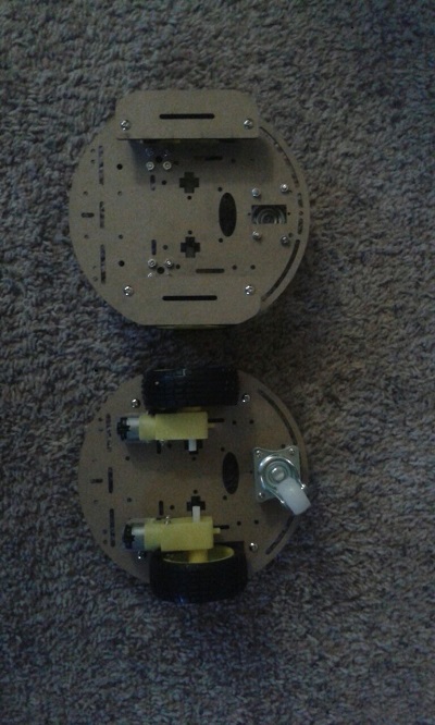
Robot assembly
2) Software - OpenCV environment setup,
Basic video processing
|
  1) Hardware, OpenCV setup - Completed
     Problems Encountered -  Hardware Bug discovered in version 0.1
     of motor controller circuit after testing.
  2) Software - Problems during filtering video for certain colors.
|
Completed |
| 2 | 4/21/2015 |
  1) Communication between OpenCV to SJone board
     using DB9 connector and UART3
  2) PWM and Ultrasonic sensor drivers
  3) Object detection and mapping
  4) Wireless communication between two nodes
|
  1) Modification of RS232 header file to support windows 7 file API.
     Was not able to communicate between OpenCV and SJone board using UART0
  2) Unable to receive the echo signal and was not able to use
     ultrasonic sensor without interrupt.
  3) HSV values had to be detected to recognize particular color.
     Had difficulties to find the HSV values for a color.
     This was solved by writing a program to print the
     HSV value of the color that is pointed in the video.
  4) Packet sending and recieving failure. System crash while
     transmitting and recieving packets
|
Completed |
| 3 | 4/28/2015 |
 1) PID Controller Design
 2) Co-ordinates communication between nodes
    and boundary mapping
 3) Inter board communication and
    communicating the Co-ordinates
|
1) Point to point travel using PID control loop. Code written PID tuning in progress. 2) Object detection completed. Co-ordinates mapping in progress. 3) Inter board communication completed. |
Completed |
| 4 | 05/05/2015 |
1) Integration, testing and Bug fixing |
- | Scheduled |
Parts List & Cost
| Serial No. | Part Description | Cost |
|---|---|---|
| 1 | Robot chassis and motors | $66.7 |
| 2 | Servo motors | $27.38 |
| 3 | Wireless camera | $26.21 |
| 4 | Ultrasonic sensor | $17.98 |
| 5 | Lipo Batteries and charger | $43.28 |
| 6 | H bridge IC - L293d | $10.91 |
| 7 | Connectors, cables etc | $45 |
| 8 | Antennas for wireless module | $15 |
| 9 | Foam board for arena | $65 |
Design & Implementation
The design section can go over your hardware and software design. Organize this section using sub-sections that go over your design and implementation.
Hardware Design
Discuss your hardware design here. Show detailed schematics, and the interface here.
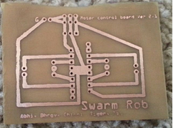
- The schematic was designed by the team and it was embedded on the PCB using the actual process carried on to embed a circuit on the PCB. This image provides the layout information of the motor driver.
- File:IR-Sensor.png


Hardware Interface
In this section, you can describe how your hardware communicates, such as which BUSes used. You can discuss your driver implementation here, such that the Software Design section is isolated to talk about high level workings rather than inner working of your project.
Software Design
Show your software design. For example, if you are designing an MP3 Player, show the tasks that you are using, and what they are doing at a high level. Do not show the details of the code. For example, do not show exact code, but you may show psuedocode and fragments of code. Keep in mind that you are showing DESIGN of your software, not the inner workings of it.
- Robot control and wireless communication is accomplished with the help of FreeRTOS software.
- Components of FreeRTOS utilized are:
- 1. FreeRTOS Task and Scheduler
- 2. FreeRTOS Queues
- 3. FreeRTOS Binary Semaphore
- 4. FreeRTOS Mutex
- FreeRTOS scheduler is used to run all the tasks on the robot.
- FreeRTOS Queues are used to communicate between tasks.
- FreeRTOS Binary Semaphore is used to enable a task.
- FreeRTOS Mutex helps in sharing resources.
- Robot to Robot communication is performed with the help of Wireless mesh network.
- PWM API developed by preet is used for controlling motors and interfacing ultrasonic sensor.
- API to read the analog values which is developed by preet is used to read the values from IR sensors
- Camera access and detection of robot is implemented on a computer with the help of openCV library.
Implementation


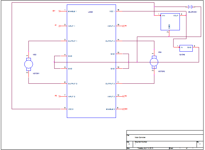
Motor Driver - This is achieved with the help of L293D H-bridge IC. It is used to drive inductive loads such as dc motors,relays etc. When the enable pin of the IC is high, respective driver is enabled. A PWM supplied to the enable pin will drive dc motor.
- Obstacle detection - This is achieved with help of an ultrasonic sensor. When the distance between two robots is less than the threshold an software Interrupt occurs and the robot changes its direction to avoid collision and moves in the direction where there is no obstacle.
- Target detection - Infrared sensors are used to detect the target,
- Detecting and locating robot - This is achieved with the help of an overhead wireless camera. Each robot will be updated with its present location.
- Detection of robot : Each robot is of a different color. This will help in differentiating the robots from one another. Images from the camera are captured every 30 millisecond, these images obtained will be in RGB format which is converted to HSV format. The converted image is then filtered. Hue(H), Saturation(S) and Value(V) are different for different color, hence the image can be filtered by defining the range for each color. The filtered image is then processed to remove noise.
- Location of robot : Each filtered image contains only one object, the outline of the object is found out and checked if the area is more than threshold. If the area is less than the threshold, then it is discarded as noise. The spatial coordinates of the outlined image is found out which gives the position of the robot.
- Communication - Each robot has unique IDs, this is utilized to communicate with a particular robot. The data between robots is exchanged with the help of inbuilt wireless module written by preet.
- Communicating locations to robots - Co-ordinates of each robot detected through openCV is transmitted to a SJone board using using DB9 connector and UART3 on SJone board. Each co-ordinate is sent with a header and Robot ID.
- If the value output from IR sensor is less than a threshold then it informs the robot that the target is found.
- SJone board connected to computer on which openCV is executed, receives the Robot Id and Co-ordinates which is transmitted to respective robots. The robots keep track of its location and direction of its movement is determined. Once the target is found, the respective robot will broadcast its present location to other robots and also indicates that the target is found.
- Upon receiving the message that target is found, the other robots will start moving towards the target location.
Testing & Technical Challenges
Describe the challenges of your project. What advise would you give yourself or someone else if your project can be started from scratch again? Make a smooth transition to testing section and described what it took to test your project.
Include sub-sections that list out a problem and solution, such as:
My Issue #1
Discuss the issue and resolution.
Conclusion
Conclude your project here. You can recap your testing and problems. You should address the "so what" part here to indicate what you ultimately learnt from this project. How has this project increased your knowledge?
Project Video
Upload a video of your project and post the link here.
Project Source Code
References
Acknowledgement
The hardware components were procured from HobbyKing, ebay, Amazon, getFPV, HomeDepot and various other sources for this project. Thanks to Preetpal Kang for teaching this class and inspiring, guiding and support us with our coursework and project. Thanks to entire team who helped and supported each other during all stages of the project and spending weekends and extra hours to get all parts of the project working.
References Used
List any references used in project.
Appendix
You can list the references you used.