Difference between revisions of "S15: SJeight Octocopter"
Proj user22 (talk | contribs) (→Team Members & Responsibilities) |
Proj user22 (talk | contribs) (→Team Members & Responsibilities) |
||
| Line 38: | Line 38: | ||
|AHRS (Attitude Heading Reference System) | |AHRS (Attitude Heading Reference System) | ||
|I2C PWM Expander | |I2C PWM Expander | ||
| + | | | ||
|- | |- | ||
|CAD Design | |CAD Design | ||
| Line 45: | Line 46: | ||
|- | |- | ||
|PID Control | |PID Control | ||
| − | | | + | |GPS |
|Remote Control | |Remote Control | ||
| | | | ||
|- | |- | ||
|GPS | |GPS | ||
| + | | | ||
|GPS | |GPS | ||
| − | | | + | | |
| + | |- | ||
| + | |AHRS (Attitude Heading Reference System) | ||
| + | | | ||
| + | | | ||
| | | | ||
|} | |} | ||
Revision as of 22:09, 16 May 2015
Contents
Grading Criteria
- How well is Software & Hardware Design described?
- How well can this report be used to reproduce this project?
- Code Quality
- Overall Report Quality:
- Software Block Diagrams
- Hardware Block Diagrams
- Schematic Quality
- Quality of technical challenges and solutions adopted.
Project Title
SJeight Octocopter
Abstract
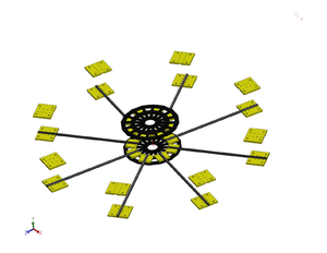
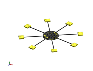
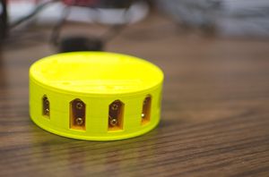
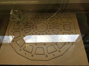
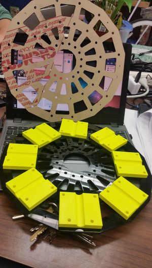
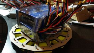
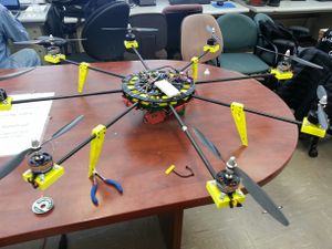
The purpose of the project is to create a large custom built octocopter. It will rely on AHRS (Attitude and Heading Reference System) to stabilize the copter. The advantage for using eight motors is reliability, since the copter can still operate with one motor disabled. Another advantage is the ability to carry a larger payload than quadcopters. There are many design challenges for this project. The first being structural support. To help this along, a professional grade laser cutter and 3D printers were used to create the frame. Power consumption, weight, thrust, and sensors were carefully considered for this project.
Objectives & Introduction
Show list of your objectives. This section includes the high level details of your project. You can write about the various sensors or peripherals you used to get your project completed.
Team Members & Responsibilities
| Christopher Sawtelle | Son Nguyen | Grant Welch | Noe Quintero |
|---|---|---|---|
| Component selection | Motor Mount | Power Hub | Frame |
| I2C PWM Expander | AHRS (Attitude Heading Reference System) | I2C PWM Expander | |
| CAD Design | CAD Design | CAD Design | CAD Design |
| PID Control | GPS | Remote Control | |
| GPS | GPS | ||
| AHRS (Attitude Heading Reference System) |
Schedule
| Week# | Date | Task | Actual |
|---|---|---|---|
| 1 | 4/12/15 | Interface with PWM expander | Work In Progress/(Problems with I2C Addressing) |
| 2 | 4/19/15 | Interface and Calibrate the AHRS with the SJone Board | |
| 3 | 4/26/15 | Add PID to SJone board | |
| 4 | 5/3/15 | Tune PID and Interface with RC Transmitter | |
| 5 | 5/10/15 | Test Flight and fine Tuning |
Parts List & Cost
| Name | Qty | Total Cost |
| Acrylic Sheet (Frame) | 1 | $30 |
| Lipo Battery | 3 | $220 |
| Carbon Fiber Rod | 8 | $120 |
| Motors | 8 | $120 |
| ESC | 8 | $192 |
| Carbon Fiber Propeller | 8 | $65 |
| Nuts and Bolts | 200 | $100 |
| Battery Connectors | 11 | $30 |
| Zip Ties | 8 | $10 |
| ABS Plastic (3D Printer) | 1 | $25 |
| 6 AWG Wire | 1 | $30 |
Design & Implementation
The design section can go over your hardware and software design. Organize this section using sub-sections that go over your design and implementation.
Hardware Design
Discuss your hardware design here. Show detailed schematics,and the interface here.
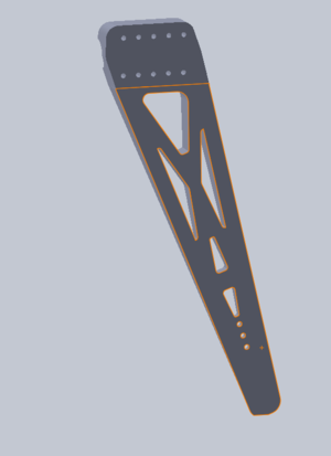
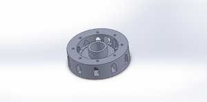
CAD Design
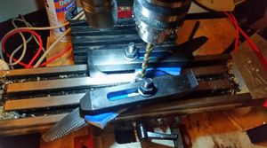
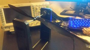
Propeller Preparation
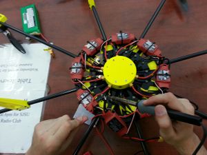
Power Hub
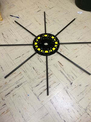
Main Frame
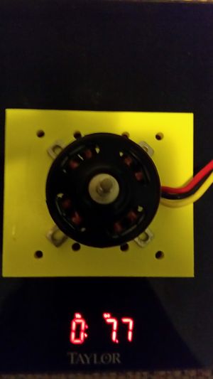
Motor and Battery
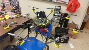
Assembly of Copter
Power Supply Circuit to 'OR' the Batteries
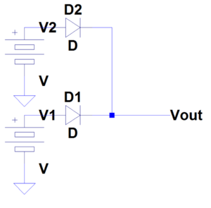
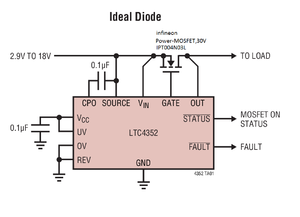
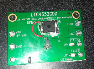
Three packs were necessary to power the copter. Unfortunately, LiPo batteries cannot be connected in parallel if the voltages are not closely matched. One solution is to use diode to prevent the batteries from back-charging one another. Luckily, there are circuits available to create diodes from transistors. One option was the LTC4352.
Hardware Interface
The SJeight interfaces with various peripherals. This includes the PCA9685 (16-channel, 12-bit PWM Fm+ I2C-bus LED controller) for PWM expansion, Razor IMU(Internal Measurement Unit) sparkfun, Adafruit Ultimate GPS Breakout Module, and 2.4GHz XBee module from Dig.
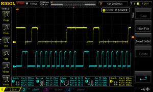
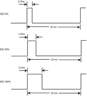
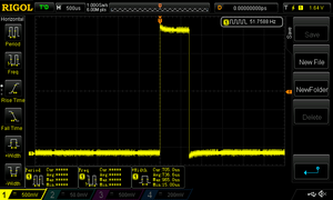
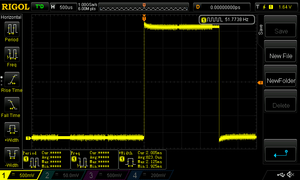
To overcome the limited number of PWM I/O on the SJone board, extra hardware needed to be added to the project. The solution was the PCA9685. It provides 16 channels for PWM for the ESC(Electronic Speed Controller). This device communicates via I2C or Inner IC communication. The following figure shows a scope shot of the I2C bus. Even though the ESC is not directly controlled by the SJone, understanding of the signals are important. The ESC accepts a very specific signal. The frequency must be 50 Hz and ave a minimum pulse width of 0.7 milliseconds. The speed of the motor is then determined by the pulse width: 0.7 ms is 0% speed, 1.5 ms is 50% speed, and 2.3 ms is 100% speed.
Software Design
Show your software design. For example, if you are designing an MP3 Player, show the tasks that you are using, and what they are doing at a high level. Do not show the details of the code. For example, do not show exact code, but you may show psuedocode and fragments of code. Keep in mind that you are showing DESIGN of your software, not the inner workings of it.
Implementation
This section includes implementation, but again, not the details, just the high level. For example, you can list the steps it takes to communicate over a sensor, or the steps needed to write a page of memory onto SPI Flash. You can include sub-sections for each of your component implementation.
Testing & Technical Challenges
Describe the challenges of your project. What advise would you give yourself or someone else if your project can be started from scratch again? Make a smooth transition to testing section and described what it took to test your project.
Include sub-sections that list out a problem and solution, such as:
Issue #1
One Issue that came up was the addressing of I2C. The datasheet for the PCA9685 presents the address as 0x40, but it is an 7-bit address. The SJeight function accepts an preshifted 8-bit address (0x80). This was discovered from probing the bus with an scope.
Issue #2
Safety!!! One of our group member was injured with the copter.
Conclusion
Conclude your project here. You can recap your testing and problems. You should address the "so what" part here to indicate what you ultimately learnt from this project. How has this project increased your knowledge?
Project Video
Upload a video of your project and post the link here.
Project Source Code
References
Acknowledgement
Any acknowledgement that you may wish to provide can be included here.
References Used
List any references used in project.
Appendix
You can list the references you used.
