Difference between revisions of "S15: Hand Gesture Recognition using IR Sensors"
Proj user9 (talk | contribs) |
Proj user9 (talk | contribs) (→Acknowledgement) |
||
| Line 248: | Line 248: | ||
=== Acknowledgement === | === Acknowledgement === | ||
<p style="text-indent: 1em; width: 700px; text-align: justify;"> | <p style="text-indent: 1em; width: 700px; text-align: justify;"> | ||
| − | All the components where procurred from Amazon, Adafruit and digikey. We are thankful to Preet for his continuous guidance during the project | + | All the components where procurred from Amazon, Adafruit and digikey. We are thankful to Preet for his continuous guidance during the project. |
</p> | </p> | ||
=== References Used === | === References Used === | ||
List any references used in project. | List any references used in project. | ||
Revision as of 19:51, 22 May 2015
Contents
Abstract
The aim of the project is to develop hand gesture recognition system using grid of IR proximity sensors. Various hand gestures like swipe, pan etc. can be recognized. These gestures can be used to control different devices or can be used in various applications. The system will recognize different hand gestures based on the values received from IR proximity sensors.
Objectives & Introduction
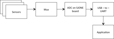
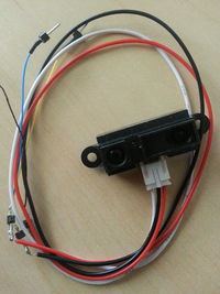
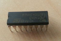
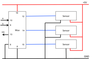
We use various hand gestures in our day-to-day life to communicate while trying to explain someone something, direct them somewhere etc. It would be so cool if we could communicate with various applications running on the computers or different devices around us understand the hand gestures and give the expected output. In order to achieve this, we are using a 3-by-3 grid of analog IR proximity sensors and connecting these sensors via multiplexers to the ADC pins on SJOne Board. As a hand is moved in front of the sensors, the sensor values would in a particular pattern enabling us to detect the gesture and instruct the application to perform the corresponding action.
Team Members & Responsibilities
- Harita Parekh
- Implementing algorithm for gesture recognition
- Implementation of sensor data filters
- Shruti Rao
- Implementing algorithm for gesture recognition
- Interfacing of sensors, multiplexers and controller
- Sushant Potdar
- Implementation of final sensor grid
- Development of the application module
Schedule
Show a simple table or figures that show your scheduled as planned before you started working on the project. Then in another table column, write down the actual schedule so that readers can see the planned vs. actual goals. The point of the schedule is for readers to assess how to pace themselves if they are doing a similar project.
| Week# | Start Date | End Date | Task | Status | Actual Completion Date |
|---|---|---|---|---|---|
| 1 | 3/22/2015 | 3/28/2015 | Research on the sensors, order sensors and multiplexers | Completed | 3/28/2015 |
| 2 | 3/29/2015 | 4/4/2015 | Read the data sheet for sensors and understand its working. Test multiplexers | Completed | 4/4/2015 |
| 3 | 4/5/2015 | 4/11/2015 | Interfacing of sensors, multiplexers and controller | Completed | 4/15/2015 |
| 4 | 4/12/2015 | 4/18/2015 |
|
Ongoing | |
| 5 | 4/19/2015 | 4/25/2015 |
|
Scheduled | |
| 6 | 4/26/2015 | 5/2/2015 |
|
Scheduled | |
| 7 | 5/3/2015 | 5/9/2015 | Testing and bug fixes | Scheduled | |
| 8 | 5/10/2015 | 5/16/2015 | Testing and final touches | Scheduled | |
| 9 | 5/25/2015 | 5/25/2015 | Final demo | Scheduled | |
Parts List & Cost
| SR# | Component Name | Quantity | Price per component | Total Price |
|---|---|---|---|---|
| 1 | Sharp Distance Measuring Sensor Unit (GP2Y0A21YK0F) | 9 | $14.95 | $134.55 |
| 2 | STMicroelectronics Dual 4-Channel Analog Multiplexer/Demultiplexer (M74HC4052) | 3 | $ | $ |
| 3 | SJ-One Board | 1 | $80 | $80 |
Design & Implementation
Hardware Design
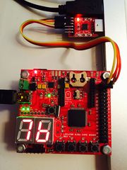
The image shows the setup of the project.
|
System Block Diagram:
|
|
|
Proximity Sensor:
|
|
|
Multiplexer:
|
|
|
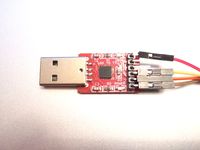
UART-to-USB convertor:
|
Hardware Interface
Software Design
Show your software design. For example, if you are designing an MP3 Player, show the tasks that you are using, and what they are doing at a high level. Do not show the details of the code. For example, do not show exact code, but you may show psuedocode and fragments of code. Keep in mind that you are showing DESIGN of your software, not the inner workings of it.
Implementation
This section includes implementation, but again, not the details, just the high level. For example, you can list the steps it takes to communicate over a sensor, or the steps needed to write a page of memory onto SPI Flash. You can include sub-sections for each of your component implementation.
Testing & Technical Challenges
Describe the challenges of your project. What advise would you give yourself or someone else if your project can be started from scratch again? Make a smooth transition to testing section and described what it took to test your project.
Include sub-sections that list out a problem and solution, such as:
My Issue #1
Discuss the issue and resolution.
Conclusion
Conclude your project here. You can recap your testing and problems. You should address the "so what" part here to indicate what you ultimately learnt from this project. How has this project increased your knowledge?
Project Video
Upload a video of your project and post the link here.
Project Source Code
References
Acknowledgement
All the components where procurred from Amazon, Adafruit and digikey. We are thankful to Preet for his continuous guidance during the project.
References Used
List any references used in project.
