S14: Power efficient security door system for light-rail using CAN bus
Contents
- 1 Grading Criteria
- 2 Power efficient security door system for light-rail using CAN bus
Grading Criteria
- How well is Software & Hardware Design described?
- How well can this report be used to reproduce this project?
- Code Quality
- Overall Report Quality:
- Software Block Diagrams
- Hardware Block Diagrams
- Schematic Quality
- Quality of technical challenges and solutions adopted.
Power efficient security door system for light-rail using CAN bus
Abstract
This project is about controlling the operations of doors and sensors in a light rail train, such that they are operated only when required, thus reducing power consumption. Currently, when a light rail halts at a station the driver opens all the doors of all the coaches. However, except for peak hours and especially during weekends and holidays, the number of people entering and exiting a train at a particular station is comparatively very low. Sometimes, only 2-3 people enter or exit a train and that too they use only 1 or 2 doors of the train. In such cases, operating all the doors is simply a waste of power. Our project provides a solution to this problem by allowing the driver to operate only selected doors as per the requirement. It senses from which coach the stop request was pressed or in front of which door the passengers are standing on a station to enter the train. Accordingly to these inputs it selectively operates only those particular doors. The rest are not operated and thus we not only save power but the reduced wear and tear of moving parts of doors enhances their lifetime. This project is based on the concept of CAN bus which is used for communication between sensors, switches and lights of different coaches of the train.
Objectives and Scope
The primary objective is to understand and implement CAN bus communication between two or more SJOne boards, such that any node can send message to any node and upon receiving a CAN message take a desired action immediately. Our secondary objective is to use CAN protocol in real time application such as to control doors, sensors and switches of different coaches of a light-rail train. This application aims at operating the doors of a train selectively as per the requirement, rather than operating all the doors. This will reduce the power consumption and increase the lifetime of the doors.
The scope of the project is:
- Successfully communicate between two or more nodes over CAN bus
- Interface a DC motor, stepper motor, smoke sensor, switches and LEDs as peripherals to SJOne board
- Develop and implement the logic to operate doors selectively as per requirement and be able to communicate between the above peripherals over three nodes
Introduction
The project insists to have LPC1758 (SJOne) controller board in each coach, which will control doors, emergency windows, indicator lights and sensors of that coach. All these SJOne boards will communicate with each other through CAN bus protocol. Whenever some event takes place like start the train, open the doors, etc. a CAN message will be sent over the bus from one board to another and it will cause the hardware to take appropriate actions. To save power consumption of the train, when a stop request switch is pressed by a passenger in one of the coach, only the doors of that coach will open at next station, while doors of other coaches will remain closed. If passengers in other coach need to exit one of them needs to press a stop request switch from that coach in order to open its doors. On the other hand, if there are passengers on the platform standing in front of the coach whose doors are closed, then they will have to press a manual switch placed near each door outside the coach, to enter the train. An alternative to this can be using a motion sensor to detect the passengers on the platform and open the door nearer to the passenger automatically. But the project first aims at implementing the CAN functionality successfully and then add other features.
Team Members & Responsibilities
- Ashish
- Concept and logic development, developing algorithm and hardware interface
- Anitha
- FreeRTOS software design, code development, verifying test cases
- Hasan
- Sensor, peripheral interface and testing of software code
Schedule
Show a simple table or figures that show your scheduled as planned before you started working on the project. Then in another table column, write down the actual schedule so that readers can see the planned vs. actual goals. The point of the schedule is for readers to assess how to pace themselves if they are doing a similar project.
| Week# | Date | Task | Actual |
|---|---|---|---|
| 1 | 02/27/2014 | Finalized scope of the project and ordered CAN transceiver TJA1040 | Completed. Deciding which tranceiver is compatible to SJone board |
| 2 | 03/06/2014 | Prepare complete block diagram with all components needed and draw the state diagram | Block diagram completed. State diagram finalization pending. Need to think more on different possibilities of event occurance when switching between states |
| 3 | 03/13/2014 | Complete state diagram and gather BOM of rest of the parts | Completed state diagram on book, but pending to draw in paint and upload on wikipage. BOM parts received. |
| 4 | 03/20/2014 | Prepare the hardware prototype boards for all three coaches | Task completed except for sensors, relays and motor interface (to be decided at the end after testing CAN functionality successfully) |
| 5 | 03/27/2014 | Read on CAN bus protocol and transceiver from datasheet | Task completed |
| 6 | 04/03/2014 | Check the transceiver along with SJone board and build basic driver to run CAN bus | Testing could not be completed successfully, understanding and testing of CAN code is in progress. |
| 7 | 04/10/2014 | Perform testing of CAN driver. Develop logic for the project and implement it on CAN bus. | Self test loop for CAN driver failed. Debugging it is in progress. (Running behind the schedule by 1 week, Need to work hard to cope-up and complete the project on time.) |
| 8 | 04/17/2014 | Testing the CAN protocol and verifying the logic. | Self test for CAN was successful, Tx and Rx between two CAN controllers was tested successfully. |
| 9 | 04/24/2014 | Interface sensors, motors and test with CAN bus protocol. | Interface of fire sensor, stepper motor was tested successfully, however DC motor is pending. CAN test for hardware level address filtering is still failing and its diagnosis is in progress |
| 10 | 05/01/2014 | Testing and debug of the prototype boards and code. | Completed DC motor interface. Successfully implemented CAN communication between all nodes using hardware level filtering |
| 11 | 05/08/2014 | Modifying the code and verifying for different test cases | Few test cases are failing. Need to fix them. |
| 12 | 05/15/2014 | Final touch-up on the design, code and prepare wikipage | Fixed the failing test cases and bugs in hardware board and the code. Wikipage is pending. |
| 13 | 05/22/2014 | Final demonstration |
Parts List & Cost
Give a simple list of the cost of your project broken down by components. Do not write long stories here.
Design & Implementation
Hardware Design
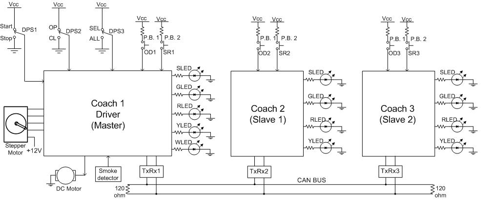
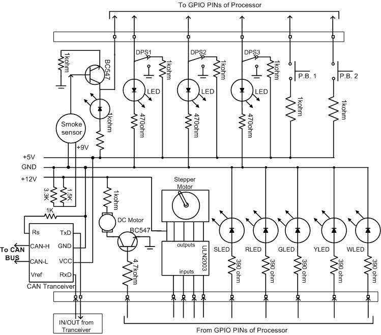
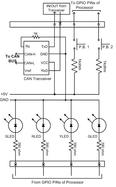
The project uses three SJOne boards and three identical prototype boards connected to each other. The prototype boards are used to interface peripherals to SJOne board. A pair of SJOne board and prototype board is considered as one node and it resembles one coach of the train. Thus, we have a train that has three coaches and we control the operation of their doors, switches and sensors. Among these three coaches, one acts as a master or engine, which will be operated by the driver and the other two works as slaves or followers of the engine. The different peripherals connected to the SJOne boards are as under.
Sensors and peripherals of engine (master) coach An engine consists of the following peripherals
- DPS1: It is a SPDT toggle switch to be operated by the driver, to “START” or “STOP” the train i.e. a DC motor
- DPS2: It is a SPDT toggle switch to be operated by the driver, to “OPEN” or “CLOSE” the doors of the train i.e. to operate a stepper motor
- DPS3: It is a SPDT toggle switch to be operated by the driver, to select whether to operate “ALL DOORS” or “SELECTED DOORS” of the train
- PB1 or OD1: It is a push button switch to be operated by passengers in the train, to request a stop
- PB2 or SR1: It is a push button switch to be operated by passengers on a station, to request opening of doors to enter the train, if the doors are closed.
- SLED: It is a red color LED that glows in response to a stop requested by a passenger
- YLED: It is a yellow color LED that glows if doors of that coach are opened
- RLED: It is a red color LED that flashes indicating it is an emergency but not safe to exit at that time
- GLED: It is a green color LED that flashes to indicate safe exit during emergency
- WLED: It is a yellow color LED that glows to indicate the driver about a open door request pressed by a passenger on the station
- Smoke sensor: To detect smoke and ring alarm indicating an emergency situation
Sensors and peripherals of follower (slave) coach In order to save the cost of identical hardware components, a slave coach does not have all the peripherals as that of a master coach. A slave consists of the following peripherals:
- PB1 or OD2/3: It is a push button switch to be operated by passengers in the train, to request a stop
- PB2 or SR2/3: It is a push button switch to be operated by passengers on a station, to request opening of doors to enter the train, if the doors are closed.
- SLED: It is a red color LED that glows in response to a stop requested by a passenger
- YLED: It is a yellow color LED that glows if doors of that coach are opened
- RLED: It is a red color LED that flashes indicating it is an emergency but not safe to exit at that time
- GLED: It is a green color LED that flashes to indicate safe exit during emergency
The block diagram of the complete system resembling a train having three coaches is as shown in figure 1. The schematic diagram of prototype board for master is shown in figure 2 and the schematic diagram of prototype board for slave is shown in figure 3.
 Figure 1. System block diagram
 Figure 2. Schematic diagram of prototype board for master (engine)
 Figure 3. Schematic diagram of prototype board for slave (followers)
Hardware Interface
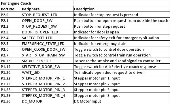
The table 1 defines the specific port pins used to interface peripherals to SJOne board for master (engine) node. The table 2 defines the specific port pins used to interface peripherals to SJOne board for slave (follower) node.
 Table 1. Pin configuration for master (engine)
 Table 2. Pin configuration for slave (followers)
Software Design
Show your software design. For example, if you are designing an MP3 Player, show the tasks that you are using, and what they are doing at a high level. Do not show the details of the code. For example, do not show exact code, but you may show psuedocode and fragments of code. Keep in mind that you are showing DESIGN of your software, not the inner workings of it.
Implementation
This section includes implementation, but again, not the details, just the high level. For example, you can list the steps it takes to communicate over a sensor, or the steps needed to write a page of memory onto SPI Flash. You can include sub-sections for each of your component implementation.
Testing & Technical Challenges
Describe the challenges of your project. What advise would you give yourself or someone else if your project can be started from scratch again? Make a smooth transition to testing section and described what it took to test your project.
Include sub-sections that list out a problem and solution, such as:
My Issue #1
Discuss the issue and resolution.
Conclusion
Conclude your project here. You can recap your testing and problems. You should address the "so what" part here to indicate what you ultimately learnt from this project. How has this project increased your knowledge?
Project Video
Upload a video of your project and post the link here.
Project Source Code
Send me your zipped source code and I will upload this to SourceForge and link it for you.
References
Acknowledgement
Any acknowledgement that you may wish to provide can be included here.
References Used
List any references used in project.
Appendix
You can list the references you used.