Difference between revisions of "S14: Need For Speed"
Proj user17 (talk | contribs) (→Team Members & Responsibilities) |
Proj user15 (talk | contribs) (→Android App Package) |
||
| (239 intermediate revisions by 3 users not shown) | |||
| Line 1: | Line 1: | ||
| − | + | [[File:Cmpe244_s14_NFS_Final.jpg|thumb|right|530px|NEED FOR SPEED..!!]] | |
| − | |||
| − | |||
| − | |||
| − | |||
| − | |||
| − | |||
| − | |||
| − | |||
| − | |||
| − | |||
| − | == | + | == '''Abstract''' == |
| + | [[File:CMPE_244_F14_PU17_fig2.png|thumb|250px|Icon for our Android App]] | ||
| + | This page contains design and implementation of our Embedded Software project, Need For Speed. It's about maneuvering an RC vehicle using the Acceleration Sensor in a smart phone. An Android Application is developed to transmit the Acceleration Sensor Signals to the vehicle via Bluetooth. The car is mounted with a Bluetooth module to receive data from the phone. And the acceleration and turning of the vehicle will be based on this data. | ||
| + | The vehicle is also mounted with two Infrared Sensor modules for collision detection, one in the front and other in the rear.Detection of any obstacle in the vehicles path will bring the vehicle to a halt state immediately. | ||
| − | == | + | == '''Introduction''' == |
| − | + | In this project we are using JY-MCU Bluetooth module to be the wireless link between the smartphone and the battery powered RC vehicle. The Android application is developed to transmit a particular byte for every threshold value of the Acceleration Sensor i.e. when the phone is one byte for front tilt and another for back. This received byte is compared by the SJOne board with few predefined values and accordingly PWM signals are given to the motors. | |
| − | + | The input of the IR sensors is connected to the hardware interrupts on the SJOne board, the interrupt subroutine will be called every time there is an obstacle in the path of the vehicle, this subroutine will in turn stop the vehicle. | |
| − | |||
| − | === | + | == '''Objectives''' == |
| − | + | As this project is both software and hardware based, our objectives were as follows; | |
| − | |||
| − | |||
| − | |||
| − | |||
| − | |||
| − | + | * '''Hardware Objectives''' | |
| − | + | ** To achieve a constant 6V DC supply for the motors and 5V DC for the board from the battery. | |
| + | ** To interface the motors to the SJOne board via L298 motor driver. | ||
| + | ** To calibrate the IR sensors to sense obstacle in 6" proximity. | ||
| + | * '''Software Objectives''' | ||
| + | ** To develop an Android application to send the data from Acceleration Sensor via Bluetooth. | ||
| + | ** To develop a FreeRTOS code to receive these signals and process them. | ||
| + | ** To develop a FreeRTOS code to send PWM sigal to the motor for variable speed. | ||
| + | ** To develop a FreeRTOS code to accept interrupt from the IR sensors and take actions accordingly. | ||
| + | |||
| + | == '''Team Members & Responsibilities''' == | ||
| + | * '''Amey Patil''' | ||
| + | ** Hardware Design | ||
| + | ** Free RTOS (Part 1: To interface motors and LPC1758 using PWM) | ||
| + | ** Free RTOS (Part 2: To configure the Bluetooth module) | ||
| + | * '''Siddhata Patil''' | ||
| + | ** Free RTOS (Part 3: To send and receive data between Bluetooth module and LPC1758) | ||
| + | ** Android Application(Part1: To send data from Android Phone to LPC1758) | ||
| + | ** Android Application(Part2: To send results of accelerometer sensor from Android Phone to LPC1758) | ||
| + | |||
| + | == '''Schedule''' == | ||
{| class="wikitable" | {| class="wikitable" | ||
|- | |- | ||
! scope="col"| Week# | ! scope="col"| Week# | ||
| − | ! scope="col"| Date | + | ! scope="col"| Planned Date |
| − | ! scope="col"| | + | ! scope="col"| Completed Date |
| − | ! scope="col"| | + | ! scope="col"| Tasks |
| + | ! scope="col"| Status | ||
| + | |- | ||
| + | | scope="row"| 1 | ||
| + | | 3/6 | ||
| + | | 3/13 | ||
| + | | Planning Hardware and placing order for the required components | ||
| + | | Completed | ||
| + | |- | ||
| + | | scope="row"| 2 | ||
| + | | 3/20 | ||
| + | | 3/20 | ||
| + | | Designing and Assembling the Hardware(Motors+Motor Driver+LPC1758) | ||
| + | | Completed | ||
| + | |- | ||
| + | | scope="row"| 3 | ||
| + | | 3/20 | ||
| + | | 3/20 | ||
| + | | Reviewing Datasheet, Pin Selection and Setting up the Software | ||
| + | | Completed | ||
| + | |- | ||
| + | | scope="row"| 4 | ||
| + | | 3/27 | ||
| + | | 3/27 | ||
| + | | Designing and Assembling the Hardware(Bluetooth Module+LPC1758) | ||
| + | | Completed | ||
| + | |- | ||
| + | | scope="row"| 5 | ||
| + | | 3/27 | ||
| + | | 3/27 | ||
| + | | Free RTOS pairing between LPC1758 and Bluetooth Module | ||
| + | | Completed | ||
| + | |- | ||
| + | | scope="row"| 6 | ||
| + | | 3/28 | ||
| + | | 3/28 | ||
| + | | Testing the pairing of Bluetooth and LPC1758 | ||
| + | | Completed | ||
| + | |- | ||
| + | | scope="row"| 7 | ||
| + | | 4/3 | ||
| + | | 4/3 | ||
| + | | Free RTOS code for PWM | ||
| + | | Completed | ||
| + | |- | ||
| + | | scope="row"| 8 | ||
| + | | 4/11 | ||
| + | | 4/18 | ||
| + | | Free RTOS code for sending and receiving data from Bluetooth | ||
| + | | Completed | ||
| + | |- | ||
| + | | scope="row"| 9 | ||
| + | | 4/18 | ||
| + | | 4/24 | ||
| + | | Android App Designing and learning basics of Android SDK | ||
| + | | Completed | ||
| + | |- | ||
| + | | scope="row"| 10 | ||
| + | | 4/24 | ||
| + | | 4/24 | ||
| + | | Android App Designing | ||
| + | | Completed | ||
| + | |- | ||
| + | | scope="row"| 11 | ||
| + | | 5/1 | ||
| + | | 5/4 | ||
| + | | Android App java code to transfer data from phone to LPC1758 | ||
| + | | Completed | ||
| + | |- | ||
| + | | scope="row"| 12 | ||
| + | | 5/7 | ||
| + | | 5/7 | ||
| + | | Android App java code to send values of accelerometer sensor to LPC1758 | ||
| + | | Completed | ||
| + | |- | ||
| + | | scope="row"| 13 | ||
| + | | 5/22 | ||
| + | | 5/22 | ||
| + | | Final Demo | ||
| + | | Completed | ||
|- | |- | ||
| − | |||
| − | |||
| − | |||
| − | |||
|} | |} | ||
| − | == Parts List & Cost == | + | == '''Parts List & Cost''' == |
| − | + | ||
| + | {| class="wikitable" | ||
| + | |- | ||
| + | ! scope="col"| Category | ||
| + | ! scope="col"| Item | ||
| + | ! scope="col"| Quantity | ||
| + | ! scope="col"| Unit Cost | ||
| + | ! scope="col"| Total Cost | ||
| + | |- | ||
| + | | scope="row"| Electronics | ||
| + | | SJOne Board | ||
| + | | 1 | ||
| + | | 80.00 | ||
| + | | 80.00 | ||
| + | |- | ||
| + | | scope="row"| | ||
| + | | 9.6V 1600mAh Rechargeable Ni-Mh Battery | ||
| + | | 1 | ||
| + | | 14.42 | ||
| + | | 14.42 | ||
| + | |- | ||
| + | | scope="row"| | ||
| + | | 6V DC Gear Motor with Tyres | ||
| + | | 4 | ||
| + | | 3.25 | ||
| + | | 13.00 | ||
| + | |- | ||
| + | | scope="row"| | ||
| + | | JY-MCU Bluetooth Module | ||
| + | | 1 | ||
| + | | 7.68 | ||
| + | | 7.68 | ||
| + | |- | ||
| + | | scope="row"| | ||
| + | | IR Transceiver Module | ||
| + | | 2 | ||
| + | | 1.00 | ||
| + | | 2.00 | ||
| + | |- | ||
| + | | scope="row"| | ||
| + | | L298 Motor Driver | ||
| + | | 1 | ||
| + | | 7.50 | ||
| + | | 7.50 | ||
| + | |- | ||
| + | | scope="row"| | ||
| + | | LM 7806 Voltage Regulator | ||
| + | | 1 | ||
| + | | 0.45 | ||
| + | | 0.45 | ||
| + | |- | ||
| + | | scope="row"| | ||
| + | | LM 7805 Voltage Regulator | ||
| + | | 1 | ||
| + | | 0.32 | ||
| + | | 0.32 | ||
| + | |- | ||
| + | | scope="row"| | ||
| + | | 10uF Electrolytic Capacitor | ||
| + | | 2 | ||
| + | | 0.13 | ||
| + | | 0.26 | ||
| + | |- | ||
| + | | scope="row"| | ||
| + | | 1uF Ceramic Capacitor | ||
| + | | 2 | ||
| + | | 0.10 | ||
| + | | 0.20 | ||
| + | |- | ||
| + | | scope="row"| Chassis | ||
| + | | Smart Car Chassis | ||
| + | | 1 | ||
| + | | 10.00 | ||
| + | | 10.00 | ||
| + | |- | ||
| + | | scope="row"| Connections | ||
| + | | Nuts, Bolts and Spacers | ||
| + | | | ||
| + | | | ||
| + | | 3.00 | ||
| + | |- | ||
| + | | scope="row"| Phone | ||
| + | | Android Smart Phone | ||
| + | | 1 | ||
| + | | | ||
| + | | | ||
| + | |- | ||
| + | | scope="row"| | ||
| + | | | ||
| + | | | ||
| + | | TOTAL | ||
| + | | $138.83 | ||
| + | |- | ||
| + | |} | ||
| + | |||
| + | =='''Design and Implementation'''== | ||
| + | |||
| + | [[File:cmpe244_s14_NFS_Block_Diagram.jpg|900px|centre|thumb|System Block Diagram]] | ||
| + | |||
| + | The above Block Diagram shows the overall implementation of the project. The accelerometer values (x, y, z) are used as an input by the android application. Depending on the instantaneous values, tilt will be determined. This tilt value will be provided to the Bluetooth for transmission. | ||
| + | At the receiver, this tilt data will be received by the Bluetooth Module and provided to the LPC 1758 board via an UART channel. The on board processor will compare the received data with the stored values and generate PWM signals accordingly. The motor driver upon reception of this will driver the vehicle in the respective direction. | ||
| + | We will see detailed explanation of the hardware and software in their respective sections. | ||
| + | |||
| + | |||
| + | ===Flowchart=== | ||
| + | [[File:Cmpe244_s14_NFS_fig19.jpg|center|thumb|400px|Flowchart for the System]] | ||
| + | |||
| + | ===Hardware Interface=== | ||
| + | |||
| + | Let us understand the whole structure piece by piece. | ||
| + | |||
| + | ====1. LPC 1758 SJOne Board==== | ||
| + | |||
| + | This board was a part of our course on Embedded Software at San Jose State University. For more information on the SJOne board [http://www.socialledge.com/sjsu/index.php?title=SJ_One_Board Click_me]. | ||
| + | |||
| + | [[File:Cmpe244_s14_NFS_Power_Schematic.jpg|thumb|400px|Power Supply Schematic.]] | ||
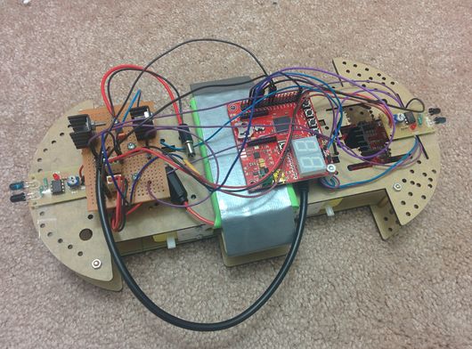
| + | ====2. Power Supply==== | ||
| + | We need to generate steady 5V supply for the board while 6V for the motors without any current limitation otherwise the motors will not give its optimum output. To our luck, LM7806 voltage regulators are also available in the market along with the LM7805. The circuit schematic is as shown in the figure above. | ||
| + | |||
| + | The total current requirement of the circuit is around 1Amp. If this much current is to be drawn through the regulators then we must make sure the heat generated is properly dissipated, so we use heat sink. Most of the current will be driven through the LM7806 regulator as it drives the motors hence, we made sure that it is not surrounded by any other component. As, the LM7805 regulator just drives the SJOne board and IR module, current flowing through it is around 100mA. Hence, this regulator won't heat as much as the other one. | ||
| + | |||
| + | |||
| + | |||
| + | [[File:Cmpe244_s14_NFS_L298_Schematic.jpg|thumb|400px|Motor Driver Schematic.]] | ||
| + | ====3. L298 Motor Driver==== | ||
| + | |||
| + | You must be thinking why didn't I use L293D as it is best for 6V motors and much easy to interface. Well, one of our motor consumes 200mA of current, which makes the total current 800mA that too in no load conditions. With load it might have seared upto 1A. Now the maximum handling capacity of L293D is 1A while that of L298 is 2A. Hence, for safety reasons I went for L298 motor driver. | ||
| + | The pin connect for this interface is as shown in the above figure. The functions of the pins are as follows; | ||
| + | |||
| + | IN1 receives 'PWM input for left motor +' from LPC 1758 and drives OUT1 | ||
| + | |||
| + | IN2 receives 'PWM input for left motor -' from LPC 1758 and drives OUT2 | ||
| + | |||
| + | IN3 receives 'PWM input for right motor +' from LPC 1758 and drives OUT3 | ||
| + | |||
| + | IN4 receives 'PWM input for right motor -' from LPC 1758 and drives OUT4 | ||
| + | |||
| + | SENSE A limits the current for Left Motor | ||
| + | |||
| + | SENSE B limits the current for Right Motor | ||
| + | |||
| + | VS: Supply voltage for the Motors | ||
| + | |||
| + | For more information on L298 Driver, [http://blog.pennybuying.com/down/f/F815A.pdf Click_me]. | ||
| + | |||
| + | |||
| + | [[File:Cmpe244_s14_NFS_IR_Schematic.jpg|thumb|400px|IR Module Schematic.]] | ||
| + | ====4. IR module==== | ||
| + | |||
| + | The IR module we are using is custom made. It is is designed to output logic '1' if any obstacle is detected or else logic '0'. The output signal from the IR receiver is directly proportional to the amount of IR waves falling on it. Hence, the output voltage for an obstacle far from the receiver will be less than that of a closer object. | ||
| + | |||
| + | In any case this output is in millivolts hence, we gave it as an input to LM358 which is a dual op-amp IC. This op-amp is configured in comparator mode. When the input at the non-inverting terminal is higher than the threshold voltage provided to the inverting terminal, the op-amp will give a logic high output. Hence, the threshold voltage is inversely proportional to the distance of the obstacle. So we connected a potentiometer at the input of the threshold voltage by which we can vary the range of obstacle detection. | ||
| + | |||
| + | In the case of IR the sensitivity of the reciever is not sufficient to detect obstacle at a longer distance. We were able to acheive obstacle detection in 2 inches of proximity. If, you are looking for detection at a longer distance, we would suggest you to go for Ultrasonic sensor modules which can even give you the distance of the obstacle from the vehicle. | ||
| + | |||
| + | Figure shows the circuit schematic of the IR module. This is circuit for one of the IR module. Two such circuits are implemented for front and back. | ||
| + | |||
| + | |||
| + | [[File:Cmpe244_s14_NFS_Bluetooth.jpg|thumb|right|400px|Bluetooth Module]] | ||
| + | ====5. Bluetooth Module==== | ||
| + | |||
| + | The module has 4 pins labeled on the back, VCC, GND, TXD and RXD. You might buy a module with two more pins KEY and STATE but it won't matter if you leave them open. The controller which it is interfaced with considers it as an serial UART device. So make sure you connect the RX and TX of the controller with TXD and RXD of the bluetooth module respectively. | ||
| + | |||
| + | |||
| + | This module works best if you are running on 3.3V, in case you are working on TTL logic then you might use a voltage divider for proper operation of the module. According to the datasheet the VCC pin is capable to handle supply ranging from 3-6V so it is fine to give TTL logic supply but, do not give TTL logic signal to the RXD pin, it cannot take anything more than 3.3V, doing such will damage the pin and hence the module. | ||
| + | |||
| + | The communication for configuration of the module is based on AT commands. There is one command for every thing, to set the device name, set the pin, set the baud rate and much more. All you have to do is to save these AT commands in the form of string and send each byte serially to the module using a simple for loop. Initially the baud rate is set to 9600. Following table shows few of the AT commands which you may require. | ||
| + | |||
| + | {| class="wikitable" | ||
| + | |- | ||
| + | ! scope="col"|Command | ||
| + | ! scope="col"|Response | ||
| + | ! scope="col"|Use | ||
| + | |- | ||
| + | | scope="row"|AT||OK || Used to verify communication | ||
| + | |- | ||
| + | | scope="row"|AT+NAMExyz||OKsetname||Sets the module name to “xyz” | ||
| + | |- | ||
| + | | scope="row"|AT+PIN1234||OKsetPIN||Sets the module PIN to 1234 | ||
| + | |- | ||
| + | | scope="row"|AT+BAUD1||OK1200||Sets the baud rate to 1200 | ||
| + | |- | ||
| + | | scope="row"|AT+BAUD2||OK2400||Sets the baud rate to 2400 | ||
| + | |- | ||
| + | | scope="row"|AT+BAUD3||OK4800||Sets the baud rate to 4800 | ||
| + | |- | ||
| + | | scope="row"|AT+BAUD4||OK9600||Sets the baud rate to 9600 | ||
| + | |- | ||
| + | | scope="row"|AT+BAUD5||OK19200||Sets the baud rate to 19200 | ||
| + | |- | ||
| + | | scope="row"|AT+BAUD6||OK38400||Sets the baud rate to 38400 | ||
| + | |- | ||
| + | | scope="row"|AT+BAUD3||OK4800||Sets the baud rate to 4800 | ||
| + | |- | ||
| + | | scope="row"|AT+BAUD4||OK9600||Sets the baud rate to 9600 | ||
| + | |} | ||
| + | |||
| + | ===Hardware Design=== | ||
| + | |||
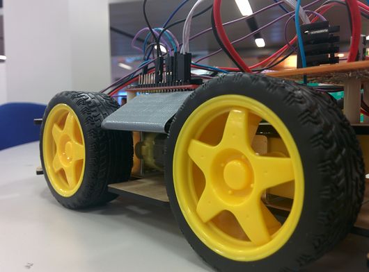
| + | It was really a task to adjust all the above mentioned tasks on an 25cm * 15 cm chasis which is made of some paper mache material (less strength). The BOT weighs around a pound increasing the load on the motor drastically. The following image on left shows the BOT in the design stage while the one on the right is our final product. | ||
| + | |||
| + | [[File:Cmpe244_s14_NFS_Hardware.jpg|thumb|left|530px|Work in progress...]] | ||
| + | [[File:Cmpe244_s14_NFS_fig1.jpg|thumb|530px|Android TA DA..!!]] | ||
| + | |||
| + | |||
| + | |||
| + | |||
| + | |||
| + | |||
| + | |||
| + | |||
| + | |||
| + | |||
| + | |||
| + | |||
| + | |||
| + | |||
| + | |||
| + | |||
| + | |||
| + | |||
| + | |||
| + | |||
| + | |||
| + | |||
| + | |||
| + | |||
| + | |||
| + | |||
| + | |||
| + | |||
| + | |||
| + | |||
| + | |||
| + | |||
| + | |||
| + | |||
| + | |||
| + | |||
| + | |||
| + | ===FreeRTOS Programming=== | ||
| + | |||
| + | In this section we will walk you through the source code for the SJOne board. Whenever a character is sent by the Bluetooth module, the UART interrupt handler code is executed. The code is as shown below. | ||
| + | |||
| + | |||
| + | |||
| + | |||
| + | |||
| + | |||
| + | |||
| + | |||
| + | |||
| + | |||
| + | |||
| + | |||
| + | |||
| + | |||
| + | |||
| + | |||
| + | |||
| + | |||
| + | |||
| + | |||
| + | |||
| + | |||
| + | void UART3_IRQHandler() | ||
| + | { | ||
| + | Uart3::getInstance().handleInterrupt(); | ||
| + | Uart3::getInstance().getChar(&in, 10000); | ||
| + | printf("%c", in); | ||
| + | motion = in; | ||
| + | } | ||
| + | |||
| + | As you can see above the data received from the Bluetooth module is stored in the motion variable. Make sure you declare the motion variable as volatile because in the main function we will be using it in an infinite while loop. Making it volatile will help the compiler understand that this variable is gonna get updated from some other source and it will compile it inside the while loop. | ||
| + | |||
| + | The following piece of code shows the initialization of the Port 2 pins P2.0, P2.1, P2.2, P2.3. Make sure you include the "lpc_pwm.hpp" before using this piece of code. | ||
| + | |||
| + | void PWM_init(){ | ||
| + | PWM left_positive(PWM::pwm1, 50); //P2.0 --> IN1 | ||
| + | PWM left_negative(PWM::pwm2, 50); //P2.1 --> IN2 | ||
| + | PWM right_positive(PWM::pwm3, 50); //P2.2 --> IN3 | ||
| + | PWM right_negative(PWM::pwm4, 50); //P2.3 --> IN4 | ||
| + | } | ||
| + | |||
| + | Below mentioned are the controlling functions for the motors. The code is well commented, one look through will be enough for you to understand the code. | ||
| + | |||
| + | void left_halt(){ | ||
| + | left_positive.set(0); | ||
| + | left_negative.set(0); | ||
| + | } | ||
| + | |||
| + | void right_halt(){ | ||
| + | right_positive.set(0); | ||
| + | right_negative.set(0); | ||
| + | } | ||
| + | |||
| + | void left_forward(float speed){ | ||
| + | if (LPC_GPIO2->FIOPIN & (1 << 7)){ // If front IR senses an obstacle. | ||
| + | left_halt(); | ||
| + | right_halt(); | ||
| + | } | ||
| + | else{ | ||
| + | left_positive.set(speed); | ||
| + | left_negative.set(0); | ||
| + | } | ||
| + | } | ||
| + | |||
| + | void left_reverse(float speed){ | ||
| + | if (LPC_GPIO2->FIOPIN & (1 << 6)){ // If rear IR senses an obstacle. | ||
| + | left_halt(); | ||
| + | right_halt(); | ||
| + | } | ||
| + | else{ | ||
| + | left_positive.set(0); | ||
| + | left_negative.set(speed); | ||
| + | } | ||
| + | } | ||
| + | |||
| + | void right_forward(float speed){ | ||
| + | if (LPC_GPIO2->FIOPIN & (1 << 7)){ // If front IR senses an obstacle. | ||
| + | left_halt(); | ||
| + | right_halt(); | ||
| + | } | ||
| + | else{ | ||
| + | right_positive.set(speed); | ||
| + | right_negative.set(0); | ||
| + | } | ||
| + | } | ||
| + | |||
| + | void right_reverse(float speed){ | ||
| + | if (LPC_GPIO2->FIOPIN & (1 << 6)){ // If rear IR senses an obstacle. | ||
| + | left_halt(); | ||
| + | right_halt(); | ||
| + | } | ||
| + | else{ | ||
| + | right_positive.set(0); | ||
| + | right_negative.set(speed); | ||
| + | } | ||
| + | } | ||
| + | |||
| + | The main function which we defined is sufficiently long hence we are giving few cases off our code to give an idea, you can use the above functions according to your requirement. Make sure the character which you send from the smartphone for a particular inclination is declared for that particular direction in the main. | ||
| + | |||
| + | int main(void) | ||
| + | { | ||
| + | LPC_GPIO2->FIODIR &= ~(1 << 7); //Front IR as input. | ||
| + | LPC_GPIO2->FIODIR &= ~(1 << 6); //Rear IR as input. | ||
| + | |||
| + | //INITIALIZED TO A HALT STATE | ||
| + | left_halt(); | ||
| + | right_halt(); | ||
| + | |||
| + | Uart3::getInstance().init(9600, 64, 64); | ||
| + | |||
| + | while(1){ | ||
| + | |||
| + | switch (motion){ | ||
| + | case 'a': // halt | ||
| + | left_halt(); | ||
| + | right_halt(); | ||
| + | break; | ||
| + | case 'n': // forward, left speed -> 50 & right speed -> 50 | ||
| + | left_forward(50); | ||
| + | right_forward(50); | ||
| + | break; | ||
| + | case 's': // forward, left speed -> 100 & right speed -> 100 | ||
| + | left_forward(100); | ||
| + | right_forward(100); | ||
| + | break; | ||
| + | case 'i': // reverse right turn, left speed -> 0 & right speed -> -50 | ||
| + | left_halt(); | ||
| + | right_reverse(50); | ||
| + | break; | ||
| + | default: | ||
| + | left_halt(); | ||
| + | right_halt(); | ||
| + | break; | ||
| + | } | ||
| + | } | ||
| + | |||
| + | return -1; | ||
| + | } | ||
| + | |||
| + | ===Android App Developement Design=== | ||
| + | |||
| + | [[File:CMPE_244_F14_PU17_fig4.png|thumb|300px|Bluetooth Pairing]] | ||
| + | ==== Using Android SDK ==== | ||
| + | In our Android Application our objective was to pair Bluetooth device on our phone with the Bluetooth module that we used with SJOne Board. For pairing of devices we used the search and scan method of Bluetooth devices instead of using IP address. Thus making it more User friendly. In the image on the right you can see how all the available Bluetooth connections show up when we start the application. | ||
| + | |||
| + | Once the pairing was done successfully we moved to the next step, which was designing of Controller for the RC Car. In this process we designed lots of controllers like remote based controller where, as you can see in the images, user can press buttons on the display to drive the BOT. | ||
| + | |||
| + | After the success in the first attempt we went for the joystick based approach where, as in the play station remote, you can swipe the joystick up and down to control the BOT. | ||
| + | |||
| + | Then finally, we went for what was our goal, motion controller, with the help of the in built Acceleration sensor of the android device. The device was calibrated to send one character for every threshold range. For example, send 'a' when the phone is held in proper viewing angle, for halt. Now when you incline the phone forward, send another character for forward motion, when you incline the phone backward, send another character for backward motion. | ||
| + | |||
| + | Sending character was opted because, it's easy to send one character than sending the values of x, y and z which are declared as float. Also, it's always efficient to send one byte (char) instead of 12 (float*3). | ||
| + | |||
| + | [[File:CMPE_244_S14_PU17_fig17.png|left|thumb|700px|Joystic controller screen]] | ||
| + | [[File:CMPE_244_F14_PU17_fig3.png|thumb|300px|Controller stage in Progress]] | ||
| + | [[File:CMPE_244_S14_PU17_fig18.png|left|thumb|700px|Accelerometer Controller screen]] | ||
| + | [[File:CMPE_244_F14_PU17_fig5.png|thumb|300px|Circled is our Android App]] | ||
| + | |||
| + | |||
| + | |||
| + | |||
| + | \ | ||
| + | |||
| + | |||
| + | |||
| + | |||
| + | |||
| + | |||
| + | |||
| + | |||
| + | |||
| + | |||
| + | |||
| + | |||
| + | ==== Android Application Developement==== | ||
| + | For Connection and Pairing of Devices, I have used the Bluetooth APIs available like Bluetooth Adapter, Bluetooth Device etc. | ||
| + | To work with Bluetooth it is very important that you add Permissions in the Android Manifest.xml. | ||
| + | The three permissions that I used were: | ||
| + | 1. android.permission.INTERNET(not needed since first we were trying to work with IP adress and wifi) | ||
| + | 2. android.permission.BLUETOOTH_ADMIN | ||
| + | 3. android.permission.BLUETOOTH | ||
| + | Here the Bluetooth Adapter is used as the first step to setup the Bluetooth connection and to verify if the bluetoothis supported or not. The Bluetooth Adapter is returned when we call static BluetoothAdapter.getDefaultAdapter(). | ||
| + | Secondly, it is very important that you enable the Bluetooth and this is done by calling startActivityForResult(). According to your requirement you can either BluetoothAdapter.ACTION_REQUEST_ENABLE or BluetoothAdapter.ACTION_STATE_CHANGED. | ||
| + | Third Task is the Discovery, for this we have to call startbtAdapter.startDiscovery(). | ||
| + | Next Task is to scan the devices available for Pairing. This is done by BluetoothAdapter.ACTION_DISCOVERY_STARTED and BluetoothAdapter.ACTION_DISCOVERY_FINISHED. And if nothing is happening check if the Bluetooth is ON if not turnOnBT(). | ||
| + | Next task is to pair the Devices. This is done by calling btAdapter.getBondedDevices(). This will return already paired devices with the Android Device you using. | ||
| + | Next step is to connect the devices which are not already paired. These devices are paired by entering the password for the device. | ||
| + | Next step is to initiate a Bluetooth Connection for sending the data. For this simply copy the code for "private class ConnectThread extends Thread" from the Bluetooth|Android Developer site. | ||
| + | Final task is set the UUID to "00001101-0000-1000-8000-00805F9B34FB" and you are good to go. | ||
| + | |||
| + | |||
| + | |||
| + | |||
| + | |||
| + | |||
| + | |||
| + | |||
| + | |||
| + | |||
| + | |||
| + | |||
| + | |||
| + | |||
| + | |||
| + | |||
| + | |||
| + | |||
| + | |||
| + | |||
| + | |||
| + | |||
| + | |||
| + | |||
| + | |||
| + | |||
| + | |||
| + | |||
| + | |||
| + | |||
| + | |||
| + | |||
| + | |||
| − | |||
| − | |||
| − | |||
| − | |||
| − | === | + | ==== Android App Package ==== |
| − | In | + | In our Android App Package, CMPE_244_NEED_FOR_SPEED, we have developed two activities. Our first Activity is the MainActivity which searches all the Bluetooth Devices possibly available and pairs the one we click on. For this purpose we have used the scanning of devices method instead of the IP Address technique. Once the pairing is successful, it will go to the next activity which is JSActivity which sends charachters and integers via bluetooth to the SJOne Board. This different data are send with the help of accelerometer Sensor in the Android Device. This is done by tilting the device. These sensor values were calibrated using the code in JSActivity. For accelerometer results, we find values of x, y and z values. These values are thus converted into integers and send via Bluetooth. We have made many projects before, until we finalized this one. We also made one spare application, in which we had a joystick kind of controller. This was done using Android Widgets. But we liked the accelerometer android app more and decided to go with it. Thus for this app, we have two files in source folder, one is MainActivity.java and other is JSActivity.java. Their corresponding xml file were written in Relative Layout format. One is activity_main.xml and other is remote_active.xml. And finally in AndroidManifest we declare the MainActivity first and after that we declare the JSActivity. |
| − | === | + | ==== Testing the Android Application ==== |
| − | |||
| − | |||
| − | |||
| − | + | [[File:CMPE_244_S14_PU17_fig6.png|right|thumb|600px|Testing on Hercules]] | |
| − | |||
| − | |||
| − | + | The Testing was carried out by using the android device in developement mode. In this mode, we had enabled USB debugging which allowed us to run our Android Application directly on our Android Device, thus saving lot of our time due to the slow emulator. When the project was build successfully, the APK file was then transfered to another android device and thus double testing was carried out. | |
| + | After the Android Application was ready, it was time to test the interface of the hardware. For this, we had to first check whether the android device was able to send data to the SJOne Board via bluetooth. This was done by connecting the SJOne Board to the Laptop. The result were seen on Hercules. If you enlarge the image you can see various numbers which show a successfull sending of the data. We have conditions like Forward, Backward, Right, Left and Halt. Each one is assigned a different integer value as seen in the screenshot. | ||
| − | == | + | == '''Technical Difficulties''' == |
| − | + | *The very first Technical Difficulty that we faced was even if the Android App Project was building successfully, it was crashing after we tried going to the controller screen. We searched online for answers and figured out that we had a problem with initialisation. So we made the required changes in onCreate method from our MainActivity and thus the problem was solved. | |
| + | *The second difficulty that we faced was that even if the devices are paired successfully, the JSActivity was not able to send data. This was happening because we first wrote a code such that the bluetooth connection was lost as soon as we switched to the next activity. Thus we modified our code and got our desired results. | ||
| − | == | + | == '''Acknowledgement''' == |
| − | |||
| − | + | We would like to thank our professor Preet. We appreciate him for the board which he has designed, it's very handy and fun to work on. | |
| − | + | To all the people who found this documentation helpful, always remember, "There is no such thing as magic. There is a reason behind everything, find the reason you will find the solution." | |
| − | == | + | == '''References''' == |
| − | + | * [https://sourceforge.net/projects/sjsu/files/CmpE244_SJSU_S2014/ Sourceforge source code link] | |
| − | == | + | === Datasheets === |
| − | + | * [1] Philips Semiconductors. LPC1758 datasheet | |
| − | + | * [2] LM 7805 - http://www.fairchildsemi.com/ds/LM/LM7805.pdf | |
| + | * [3] LM 7806 - http://www.fairchildsemi.com/pf/LM/LM7806.html | ||
| + | * [4] L298 - https://www.sparkfun.com/datasheets/Robotics/L298_H_Bridge.pdf | ||
| − | === | + | === Links === |
| − | + | * [1] Bluetooth Connectivity Thread - http://developer.android.com/guide/topics/connectivity/bluetooth.html | |
| + | * [2] Joystick Controller Display Screen - http://code.google.com/p/mobile-anarchy-widgets/source/browse/#svn%2Ftrunk%2FWidgets%2Fsrc%2Fcom%2FMobileAnarchy%2FAndroid%2FWidgets%2FJoystick%253Fstate%253Dclosed | ||
| + | * [3] Bluetooth Pairing Lectures - http://www.youtube.com/watch?v=OTQHZ16q0Ik | ||
| + | * [4] L298 Motor Driver - http://blog.pennybuying.com/down/f/F815A.pdf | ||
| + | * [5] Bluetooth Module - http://mcuoneclipse.com/2013/06/19/using-the-hc-06-bluetooth-module/ | ||
=== Appendix === | === Appendix === | ||
| − | + | * [Project source code is available at SourceForge] | |
| + | * [Project Demonstration Video] | ||
Latest revision as of 22:48, 3 June 2016
Contents
- 1 Abstract
- 2 Introduction
- 3 Objectives
- 4 Team Members & Responsibilities
- 5 Schedule
- 6 Parts List & Cost
- 7 Design and Implementation
- 8 Technical Difficulties
- 9 Acknowledgement
- 10 References
Abstract
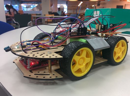
This page contains design and implementation of our Embedded Software project, Need For Speed. It's about maneuvering an RC vehicle using the Acceleration Sensor in a smart phone. An Android Application is developed to transmit the Acceleration Sensor Signals to the vehicle via Bluetooth. The car is mounted with a Bluetooth module to receive data from the phone. And the acceleration and turning of the vehicle will be based on this data. The vehicle is also mounted with two Infrared Sensor modules for collision detection, one in the front and other in the rear.Detection of any obstacle in the vehicles path will bring the vehicle to a halt state immediately.
Introduction
In this project we are using JY-MCU Bluetooth module to be the wireless link between the smartphone and the battery powered RC vehicle. The Android application is developed to transmit a particular byte for every threshold value of the Acceleration Sensor i.e. when the phone is one byte for front tilt and another for back. This received byte is compared by the SJOne board with few predefined values and accordingly PWM signals are given to the motors.
The input of the IR sensors is connected to the hardware interrupts on the SJOne board, the interrupt subroutine will be called every time there is an obstacle in the path of the vehicle, this subroutine will in turn stop the vehicle.
Objectives
As this project is both software and hardware based, our objectives were as follows;
- Hardware Objectives
- To achieve a constant 6V DC supply for the motors and 5V DC for the board from the battery.
- To interface the motors to the SJOne board via L298 motor driver.
- To calibrate the IR sensors to sense obstacle in 6" proximity.
- Software Objectives
- To develop an Android application to send the data from Acceleration Sensor via Bluetooth.
- To develop a FreeRTOS code to receive these signals and process them.
- To develop a FreeRTOS code to send PWM sigal to the motor for variable speed.
- To develop a FreeRTOS code to accept interrupt from the IR sensors and take actions accordingly.
Team Members & Responsibilities
- Amey Patil
- Hardware Design
- Free RTOS (Part 1: To interface motors and LPC1758 using PWM)
- Free RTOS (Part 2: To configure the Bluetooth module)
- Siddhata Patil
- Free RTOS (Part 3: To send and receive data between Bluetooth module and LPC1758)
- Android Application(Part1: To send data from Android Phone to LPC1758)
- Android Application(Part2: To send results of accelerometer sensor from Android Phone to LPC1758)
Schedule
| Week# | Planned Date | Completed Date | Tasks | Status |
|---|---|---|---|---|
| 1 | 3/6 | 3/13 | Planning Hardware and placing order for the required components | Completed |
| 2 | 3/20 | 3/20 | Designing and Assembling the Hardware(Motors+Motor Driver+LPC1758) | Completed |
| 3 | 3/20 | 3/20 | Reviewing Datasheet, Pin Selection and Setting up the Software | Completed |
| 4 | 3/27 | 3/27 | Designing and Assembling the Hardware(Bluetooth Module+LPC1758) | Completed |
| 5 | 3/27 | 3/27 | Free RTOS pairing between LPC1758 and Bluetooth Module | Completed |
| 6 | 3/28 | 3/28 | Testing the pairing of Bluetooth and LPC1758 | Completed |
| 7 | 4/3 | 4/3 | Free RTOS code for PWM | Completed |
| 8 | 4/11 | 4/18 | Free RTOS code for sending and receiving data from Bluetooth | Completed |
| 9 | 4/18 | 4/24 | Android App Designing and learning basics of Android SDK | Completed |
| 10 | 4/24 | 4/24 | Android App Designing | Completed |
| 11 | 5/1 | 5/4 | Android App java code to transfer data from phone to LPC1758 | Completed |
| 12 | 5/7 | 5/7 | Android App java code to send values of accelerometer sensor to LPC1758 | Completed |
| 13 | 5/22 | 5/22 | Final Demo | Completed |
Parts List & Cost
| Category | Item | Quantity | Unit Cost | Total Cost |
|---|---|---|---|---|
| Electronics | SJOne Board | 1 | 80.00 | 80.00 |
| 9.6V 1600mAh Rechargeable Ni-Mh Battery | 1 | 14.42 | 14.42 | |
| 6V DC Gear Motor with Tyres | 4 | 3.25 | 13.00 | |
| JY-MCU Bluetooth Module | 1 | 7.68 | 7.68 | |
| IR Transceiver Module | 2 | 1.00 | 2.00 | |
| L298 Motor Driver | 1 | 7.50 | 7.50 | |
| LM 7806 Voltage Regulator | 1 | 0.45 | 0.45 | |
| LM 7805 Voltage Regulator | 1 | 0.32 | 0.32 | |
| 10uF Electrolytic Capacitor | 2 | 0.13 | 0.26 | |
| 1uF Ceramic Capacitor | 2 | 0.10 | 0.20 | |
| Chassis | Smart Car Chassis | 1 | 10.00 | 10.00 |
| Connections | Nuts, Bolts and Spacers | 3.00 | ||
| Phone | Android Smart Phone | 1 | ||
| TOTAL | $138.83 |
Design and Implementation
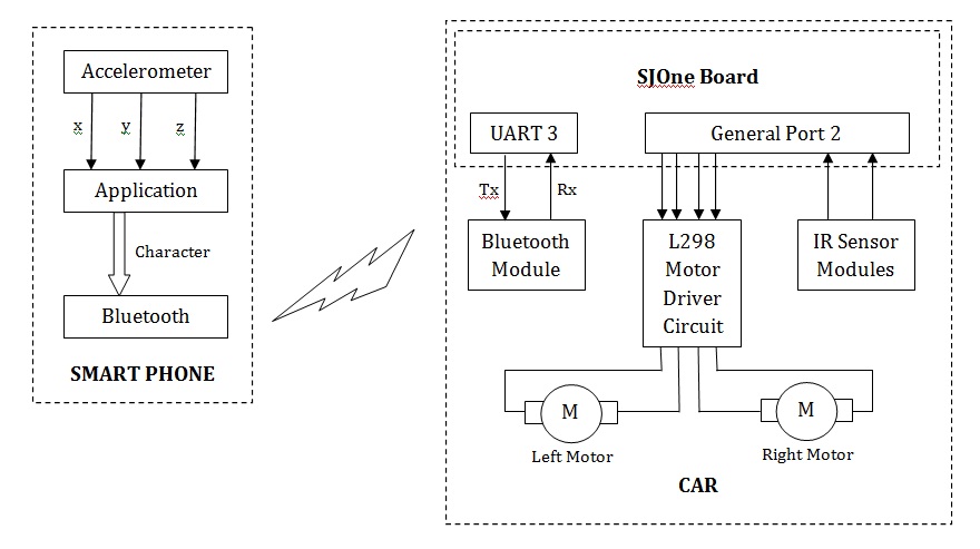
The above Block Diagram shows the overall implementation of the project. The accelerometer values (x, y, z) are used as an input by the android application. Depending on the instantaneous values, tilt will be determined. This tilt value will be provided to the Bluetooth for transmission. At the receiver, this tilt data will be received by the Bluetooth Module and provided to the LPC 1758 board via an UART channel. The on board processor will compare the received data with the stored values and generate PWM signals accordingly. The motor driver upon reception of this will driver the vehicle in the respective direction. We will see detailed explanation of the hardware and software in their respective sections.
Flowchart
Hardware Interface
Let us understand the whole structure piece by piece.
1. LPC 1758 SJOne Board
This board was a part of our course on Embedded Software at San Jose State University. For more information on the SJOne board Click_me.
2. Power Supply
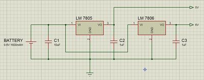
We need to generate steady 5V supply for the board while 6V for the motors without any current limitation otherwise the motors will not give its optimum output. To our luck, LM7806 voltage regulators are also available in the market along with the LM7805. The circuit schematic is as shown in the figure above.
The total current requirement of the circuit is around 1Amp. If this much current is to be drawn through the regulators then we must make sure the heat generated is properly dissipated, so we use heat sink. Most of the current will be driven through the LM7806 regulator as it drives the motors hence, we made sure that it is not surrounded by any other component. As, the LM7805 regulator just drives the SJOne board and IR module, current flowing through it is around 100mA. Hence, this regulator won't heat as much as the other one.
3. L298 Motor Driver
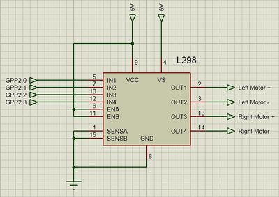
You must be thinking why didn't I use L293D as it is best for 6V motors and much easy to interface. Well, one of our motor consumes 200mA of current, which makes the total current 800mA that too in no load conditions. With load it might have seared upto 1A. Now the maximum handling capacity of L293D is 1A while that of L298 is 2A. Hence, for safety reasons I went for L298 motor driver. The pin connect for this interface is as shown in the above figure. The functions of the pins are as follows;
IN1 receives 'PWM input for left motor +' from LPC 1758 and drives OUT1
IN2 receives 'PWM input for left motor -' from LPC 1758 and drives OUT2
IN3 receives 'PWM input for right motor +' from LPC 1758 and drives OUT3
IN4 receives 'PWM input for right motor -' from LPC 1758 and drives OUT4
SENSE A limits the current for Left Motor
SENSE B limits the current for Right Motor
VS: Supply voltage for the Motors
For more information on L298 Driver, Click_me.
4. IR module
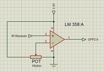
The IR module we are using is custom made. It is is designed to output logic '1' if any obstacle is detected or else logic '0'. The output signal from the IR receiver is directly proportional to the amount of IR waves falling on it. Hence, the output voltage for an obstacle far from the receiver will be less than that of a closer object.
In any case this output is in millivolts hence, we gave it as an input to LM358 which is a dual op-amp IC. This op-amp is configured in comparator mode. When the input at the non-inverting terminal is higher than the threshold voltage provided to the inverting terminal, the op-amp will give a logic high output. Hence, the threshold voltage is inversely proportional to the distance of the obstacle. So we connected a potentiometer at the input of the threshold voltage by which we can vary the range of obstacle detection.
In the case of IR the sensitivity of the reciever is not sufficient to detect obstacle at a longer distance. We were able to acheive obstacle detection in 2 inches of proximity. If, you are looking for detection at a longer distance, we would suggest you to go for Ultrasonic sensor modules which can even give you the distance of the obstacle from the vehicle.
Figure shows the circuit schematic of the IR module. This is circuit for one of the IR module. Two such circuits are implemented for front and back.
5. Bluetooth Module
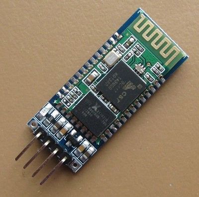
The module has 4 pins labeled on the back, VCC, GND, TXD and RXD. You might buy a module with two more pins KEY and STATE but it won't matter if you leave them open. The controller which it is interfaced with considers it as an serial UART device. So make sure you connect the RX and TX of the controller with TXD and RXD of the bluetooth module respectively.
This module works best if you are running on 3.3V, in case you are working on TTL logic then you might use a voltage divider for proper operation of the module. According to the datasheet the VCC pin is capable to handle supply ranging from 3-6V so it is fine to give TTL logic supply but, do not give TTL logic signal to the RXD pin, it cannot take anything more than 3.3V, doing such will damage the pin and hence the module.
The communication for configuration of the module is based on AT commands. There is one command for every thing, to set the device name, set the pin, set the baud rate and much more. All you have to do is to save these AT commands in the form of string and send each byte serially to the module using a simple for loop. Initially the baud rate is set to 9600. Following table shows few of the AT commands which you may require.
| Command | Response | Use |
|---|---|---|
| AT | OK | Used to verify communication |
| AT+NAMExyz | OKsetname | Sets the module name to “xyz” |
| AT+PIN1234 | OKsetPIN | Sets the module PIN to 1234 |
| AT+BAUD1 | OK1200 | Sets the baud rate to 1200 |
| AT+BAUD2 | OK2400 | Sets the baud rate to 2400 |
| AT+BAUD3 | OK4800 | Sets the baud rate to 4800 |
| AT+BAUD4 | OK9600 | Sets the baud rate to 9600 |
| AT+BAUD5 | OK19200 | Sets the baud rate to 19200 |
| AT+BAUD6 | OK38400 | Sets the baud rate to 38400 |
| AT+BAUD3 | OK4800 | Sets the baud rate to 4800 |
| AT+BAUD4 | OK9600 | Sets the baud rate to 9600 |
Hardware Design
It was really a task to adjust all the above mentioned tasks on an 25cm * 15 cm chasis which is made of some paper mache material (less strength). The BOT weighs around a pound increasing the load on the motor drastically. The following image on left shows the BOT in the design stage while the one on the right is our final product.
FreeRTOS Programming
In this section we will walk you through the source code for the SJOne board. Whenever a character is sent by the Bluetooth module, the UART interrupt handler code is executed. The code is as shown below.
   void UART3_IRQHandler()
   {
       Uart3::getInstance().handleInterrupt();
       Uart3::getInstance().getChar(&in, 10000);
       printf("%c", in);
       motion = in;
   }
As you can see above the data received from the Bluetooth module is stored in the motion variable. Make sure you declare the motion variable as volatile because in the main function we will be using it in an infinite while loop. Making it volatile will help the compiler understand that this variable is gonna get updated from some other source and it will compile it inside the while loop.
The following piece of code shows the initialization of the Port 2 pins P2.0, P2.1, P2.2, P2.3. Make sure you include the "lpc_pwm.hpp" before using this piece of code.
   void PWM_init(){
       PWM left_positive(PWM::pwm1, 50);   //P2.0 --> IN1
       PWM left_negative(PWM::pwm2, 50);   //P2.1 --> IN2
       PWM right_positive(PWM::pwm3, 50);  //P2.2 --> IN3
       PWM right_negative(PWM::pwm4, 50);  //P2.3 --> IN4
   }
Below mentioned are the controlling functions for the motors. The code is well commented, one look through will be enough for you to understand the code.
   void left_halt(){
       left_positive.set(0);
       left_negative.set(0);
   }

   void right_halt(){
       right_positive.set(0);
       right_negative.set(0);
   }

   void left_forward(float speed){
       if (LPC_GPIO2->FIOPIN & (1 << 7)){  // If front IR senses an obstacle.
           left_halt();
           right_halt();
       }
       else{
           left_positive.set(speed);
           left_negative.set(0);
       }
   }

   void left_reverse(float speed){
       if (LPC_GPIO2->FIOPIN & (1 << 6)){  // If rear IR senses an obstacle.
           left_halt();
           right_halt();
       }
       else{
           left_positive.set(0);
           left_negative.set(speed);
       }
   }

   void right_forward(float speed){
       if (LPC_GPIO2->FIOPIN & (1 << 7)){  // If front IR senses an obstacle.
           left_halt();
           right_halt();
       }
       else{
           right_positive.set(speed);
           right_negative.set(0);
       }
   }

   void right_reverse(float speed){
       if (LPC_GPIO2->FIOPIN & (1 << 6)){  // If rear IR senses an obstacle.
           left_halt();
           right_halt();
       }
       else{
           right_positive.set(0);
           right_negative.set(speed);
       }
   }
The main function which we defined is sufficiently long hence we are giving few cases off our code to give an idea, you can use the above functions according to your requirement. Make sure the character which you send from the smartphone for a particular inclination is declared for that particular direction in the main.
   int main(void)
   {
       LPC_GPIO2->FIODIR &= ~(1 << 7);     //Front IR as input.
       LPC_GPIO2->FIODIR &= ~(1 << 6);     //Rear IR as input.

       //INITIALIZED TO A HALT STATE
       left_halt();
       right_halt();

       Uart3::getInstance().init(9600, 64, 64);

       while(1){

           switch (motion){
           case 'a': // halt
               left_halt();
               right_halt();
               break;
           case 'n': // forward, left speed -> 50 & right speed -> 50
               left_forward(50);
               right_forward(50);
               break;
           case 's': // forward, left speed -> 100 & right speed -> 100
               left_forward(100);
               right_forward(100);
               break;
           case 'i': // reverse right turn, left speed -> 0 & right speed -> -50
               left_halt();
               right_reverse(50);
               break;
           default:
               left_halt();
               right_halt();
               break;
           }
       }

       return -1;
   }
Android App Developement Design
Using Android SDK
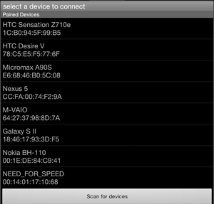
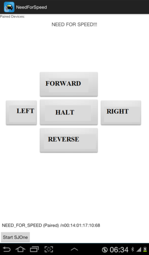
In our Android Application our objective was to pair Bluetooth device on our phone with the Bluetooth module that we used with SJOne Board. For pairing of devices we used the search and scan method of Bluetooth devices instead of using IP address. Thus making it more User friendly. In the image on the right you can see how all the available Bluetooth connections show up when we start the application.
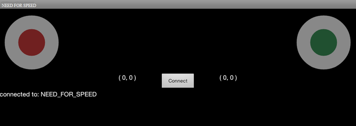
Once the pairing was done successfully we moved to the next step, which was designing of Controller for the RC Car. In this process we designed lots of controllers like remote based controller where, as you can see in the images, user can press buttons on the display to drive the BOT.
After the success in the first attempt we went for the joystick based approach where, as in the play station remote, you can swipe the joystick up and down to control the BOT.
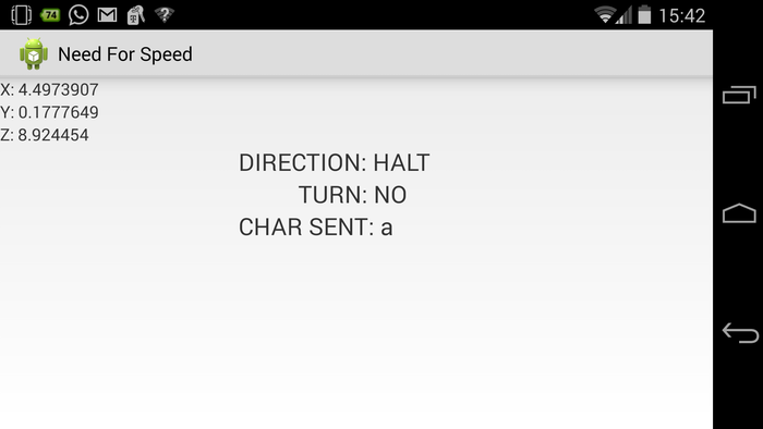
Then finally, we went for what was our goal, motion controller, with the help of the in built Acceleration sensor of the android device. The device was calibrated to send one character for every threshold range. For example, send 'a' when the phone is held in proper viewing angle, for halt. Now when you incline the phone forward, send another character for forward motion, when you incline the phone backward, send another character for backward motion.
Sending character was opted because, it's easy to send one character than sending the values of x, y and z which are declared as float. Also, it's always efficient to send one byte (char) instead of 12 (float*3).
\
Android Application Developement
For Connection and Pairing of Devices, I have used the Bluetooth APIs available like Bluetooth Adapter, Bluetooth Device etc. To work with Bluetooth it is very important that you add Permissions in the Android Manifest.xml. The three permissions that I used were: 1. android.permission.INTERNET(not needed since first we were trying to work with IP adress and wifi) 2. android.permission.BLUETOOTH_ADMIN 3. android.permission.BLUETOOTH Here the Bluetooth Adapter is used as the first step to setup the Bluetooth connection and to verify if the bluetoothis supported or not. The Bluetooth Adapter is returned when we call static BluetoothAdapter.getDefaultAdapter(). Secondly, it is very important that you enable the Bluetooth and this is done by calling startActivityForResult(). According to your requirement you can either BluetoothAdapter.ACTION_REQUEST_ENABLE or BluetoothAdapter.ACTION_STATE_CHANGED. Third Task is the Discovery, for this we have to call startbtAdapter.startDiscovery(). Next Task is to scan the devices available for Pairing. This is done by BluetoothAdapter.ACTION_DISCOVERY_STARTED and BluetoothAdapter.ACTION_DISCOVERY_FINISHED. And if nothing is happening check if the Bluetooth is ON if not turnOnBT(). Next task is to pair the Devices. This is done by calling btAdapter.getBondedDevices(). This will return already paired devices with the Android Device you using. Next step is to connect the devices which are not already paired. These devices are paired by entering the password for the device. Next step is to initiate a Bluetooth Connection for sending the data. For this simply copy the code for "private class ConnectThread extends Thread" from the Bluetooth|Android Developer site. Final task is set the UUID to "00001101-0000-1000-8000-00805F9B34FB" and you are good to go.
Android App Package
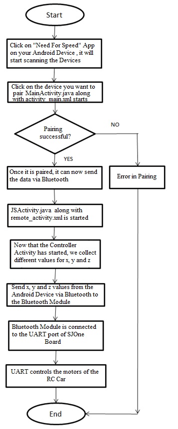
In our Android App Package, CMPE_244_NEED_FOR_SPEED, we have developed two activities. Our first Activity is the MainActivity which searches all the Bluetooth Devices possibly available and pairs the one we click on. For this purpose we have used the scanning of devices method instead of the IP Address technique. Once the pairing is successful, it will go to the next activity which is JSActivity which sends charachters and integers via bluetooth to the SJOne Board. This different data are send with the help of accelerometer Sensor in the Android Device. This is done by tilting the device. These sensor values were calibrated using the code in JSActivity. For accelerometer results, we find values of x, y and z values. These values are thus converted into integers and send via Bluetooth. We have made many projects before, until we finalized this one. We also made one spare application, in which we had a joystick kind of controller. This was done using Android Widgets. But we liked the accelerometer android app more and decided to go with it. Thus for this app, we have two files in source folder, one is MainActivity.java and other is JSActivity.java. Their corresponding xml file were written in Relative Layout format. One is activity_main.xml and other is remote_active.xml. And finally in AndroidManifest we declare the MainActivity first and after that we declare the JSActivity.
Testing the Android Application
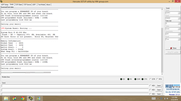
The Testing was carried out by using the android device in developement mode. In this mode, we had enabled USB debugging which allowed us to run our Android Application directly on our Android Device, thus saving lot of our time due to the slow emulator. When the project was build successfully, the APK file was then transfered to another android device and thus double testing was carried out. After the Android Application was ready, it was time to test the interface of the hardware. For this, we had to first check whether the android device was able to send data to the SJOne Board via bluetooth. This was done by connecting the SJOne Board to the Laptop. The result were seen on Hercules. If you enlarge the image you can see various numbers which show a successfull sending of the data. We have conditions like Forward, Backward, Right, Left and Halt. Each one is assigned a different integer value as seen in the screenshot.
Technical Difficulties
- The very first Technical Difficulty that we faced was even if the Android App Project was building successfully, it was crashing after we tried going to the controller screen. We searched online for answers and figured out that we had a problem with initialisation. So we made the required changes in onCreate method from our MainActivity and thus the problem was solved.
- The second difficulty that we faced was that even if the devices are paired successfully, the JSActivity was not able to send data. This was happening because we first wrote a code such that the bluetooth connection was lost as soon as we switched to the next activity. Thus we modified our code and got our desired results.
Acknowledgement
We would like to thank our professor Preet. We appreciate him for the board which he has designed, it's very handy and fun to work on. To all the people who found this documentation helpful, always remember, "There is no such thing as magic. There is a reason behind everything, find the reason you will find the solution."
References
Datasheets
- [1] Philips Semiconductors. LPC1758 datasheet
- [2] LM 7805 - http://www.fairchildsemi.com/ds/LM/LM7805.pdf
- [3] LM 7806 - http://www.fairchildsemi.com/pf/LM/LM7806.html
- [4] L298 - https://www.sparkfun.com/datasheets/Robotics/L298_H_Bridge.pdf
Links
- [1] Bluetooth Connectivity Thread - http://developer.android.com/guide/topics/connectivity/bluetooth.html
- [2] Joystick Controller Display Screen - http://code.google.com/p/mobile-anarchy-widgets/source/browse/#svn%2Ftrunk%2FWidgets%2Fsrc%2Fcom%2FMobileAnarchy%2FAndroid%2FWidgets%2FJoystick%253Fstate%253Dclosed
- [3] Bluetooth Pairing Lectures - http://www.youtube.com/watch?v=OTQHZ16q0Ik
- [4] L298 Motor Driver - http://blog.pennybuying.com/down/f/F815A.pdf
- [5] Bluetooth Module - http://mcuoneclipse.com/2013/06/19/using-the-hc-06-bluetooth-module/
Appendix
- [Project source code is available at SourceForge]
- [Project Demonstration Video]
