Difference between revisions of "S14: Autonomous Control System"
Proj user8 (talk | contribs) (→References Used) |
(→Project Source Code) |
||
| Line 481: | Line 481: | ||
=== Project Source Code === | === Project Source Code === | ||
| − | + | * [https://sourceforge.net/projects/sjsu/files/CmpE244_SJSU_S2014/ Sourceforge source code link] | |
== References == | == References == | ||
Latest revision as of 00:00, 7 August 2014
Contents
Spartan Superway Control System

Abstract
SJSU’s Spartan Superway will provide an automated, solar-powered PRT system. The objective of this particular project, within the Superway initiative, was to develop an autonomous control system for all pods (vehicles) using a wireless mesh architecture. The control system is to communicate with a central computer that would send new destinations to pods as they arrive at a station. The pods are to navigate the track system autonomously and communicate updates on their location to the master computer. This project is part of the larger SJSU Spartan Superway, more information on the project can be found at: Spartan Superway Homepage
Objectives & Introduction
The main purpose of this project is to design an Autonomous Control System for the Spartan Superway project initiative. The control system must be able to do the following:
- Wireless Communication
- Pods must communicate their location to a master computer and tell the master computer when ready for new route.
- A master computer must send new destinations to pods when their route is complete.
- Master computer knows the location of each pod on the system, throughout the travel time.
- Pods must display intelligence, and navigate a track autonomously.
- A line follower must be designed to demonstrate a working control system.
- A State Machine will operate the pods as the central component on each pod.
- Pods (vehicles) on the system must autonomously navigate a given track using a combination of IR sensors and directions generated by a shortest path algorithm (Dijkstra).
- All operations must be executed in real time, therefore use of the FreeRTOS is necessary.
Team Members & Responsibilities
- Elizabeth Poche
- Driver & Line Follower Development
- Eriberto Velazquez
- FreeRTOS Software Design
- Trent Smith
- SNAP Communication
Schedule
| Week# | Date | Planned | Actual |
|---|---|---|---|
| 1 | 3/28 |
|
|
| 2 | 4/4 |
|
|
| 3 | 4/11 |
|
|
| 4 | 4/18 |
|
|
| 5 | 4/25 |
|
|
| 6 | 5/2 |
|
|
| 7 | 5/9 |
|
|
| 8 | 5/16 |
|
|
Parts List & Cost
| Name | Part | Quantity | Cost Each | Total Cost |
|---|---|---|---|---|
| Pod Chassis | Arduino Compatible Magician Chassis | 3 | $15 | $45 |
| H-Bridge | L298 | 3 | $3.64 | $10.92 |
| IR LED/Sensor | TCRT5000 | 15 | $0.58 | $8.69 |
| DC Battery | Tenergy 9.6V 2000mAh NiMH Battery | 3 | $23.55 | $70.65 |
| SJOne Board | LPC1758 Development Board | 3 | $60 | $180 |
| Buck Converter | LM2596 | 3 | $3.00 | $9.00 |
| Voltage Regulator | NTE 960 | 3 | $2.00 | $6.00 |
| 4-1 Mux | 74HC153 | 3 | $1.00 | $3.00 |
| Hex Inverters | 74LS04N | 3 | $0 | $0 |
| SNAP Wireless | RF266PC1 | 3 | $0 | $0 |
Design & Implementation
Hardware Design

The main hardware components used in this project include:
- SJOne LPC1758 Development Board
- Motor Driver
- IR LEDs
- Mux
- Inverters
- Battery
- Buck Converter
- 5V Voltage Regulator
- SNAP Wireless
- Chassis and Motors
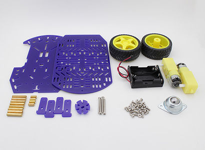
Pod Chassis and Motors
This is the frame of the pod where parts can be attached to. The chassis includes two DC motors.
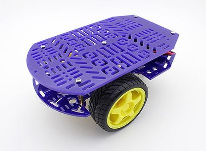
Figure 1: Pod Chassis


SJOne LPC1758 Development Board
This is the 'brains' of this project. The development board package uses FreeRTOS C/C++ and provides UART and SPI ports which are used in this project.

Mux Logic
When the pod reached a node it will take a new instruction from the state machine to either continue straight, turn right, or stop. Figure 3 and Table 1 show the mux logic and the four different modes it can be in depending on a and b inputs. If the pod was instructed to continue straight through node, the software chose straight mode and turned on both wheels until either Left AND Right, OR LLeft AND Left AND RRight, OR LLeft AND Right AND RRight signals saw white. If the pod was instructed to turn right, the software chose right mode and turned off the right wheel and turned on the left wheel until LLeft AND Left OR LLeft AND Right signals saw white. If the pod was instructed to stop, the software went into RC mode and since the station was black, the sensors did not see a reflection and therefor stopped both wheels. The pod remained stopped and waited for the next instruction.
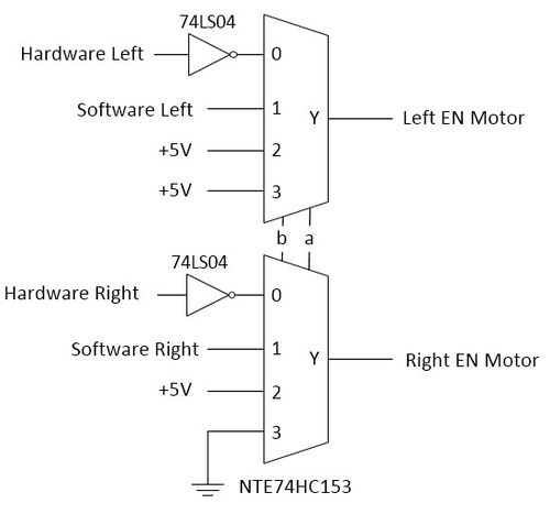
Figure 3: Mux Logic
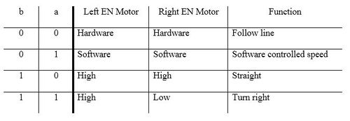
Table 1: Mux Table


IR LEDs
The IR LEDs contain and emitter and a sensor. The emitter will always provide an IR signal. The sensor will only sense the IR if the IR is reflected back.

When IR signal hits reflective ground, the signal will reflect back to the sensor and the sensor will output a false logic.

When IR signal hits non-reflective ground, the signal will not reflect back to the sensor and the sensor will output a true logic.

Motor Driver
The motor driver controls the left and right motors. The Left EN Motor and Right EN Motor pins will enable or disable the motors. Both wheels are tied to go only forward.

Voltage Regulators
The voltage regulators are used to step down the voltage from the battery pack. The buck converter is used control the voltage level to the motors, shown in Figure 8. To increase the speed of the motors, adjust the POT.

The 5V voltage regulator is used for the SJOne board, inverter, mux, and pin enables.

Battery
This provides power to all components on pod.

Station Design
The station design allows the pod to fork to another track and off the main track. The pod will sense a node using LLeft and RRight sensors and receive a new instruction from the queue.
When a right instruction is given, the pod will stop its right wheel and turn on the left wheel. When straight instruction is given, the pod will turn on both right and left wheels. When stop instruction is given, the pod will stop both left and right wheels.

Track Design
The track was designed to have three stations and a fork and merge, not counting station's fork and merge. Between each node there is a given weight of the path. This represents the length of the track. The algorithm will calculate the shortest path using these weights.


SNAP Wireless
This is used to connect the pod with the master controller.

Hardware Interface
To implement the pod system, small steps had to be taken to avoid periods if the hardware design did not work and could not isolate the issue. In the event the design did not work there was a previous design that worked. The design process started with a baseline using a simple prototype. A simple line follower was built to learn the basics of the line follower. To make the pod intelligent, a microprocessor was integrated. To get the line follower working, hardware and software were combined. Hardware controlled the pod, which followed the line and software gave user the control over the pod’s path traversal. The line follower followed a line using IR emitters and receivers, which pointed down, toward the ground. The emitter sent a constant IR signal. If the signal hit white part of the track layout, the signal reflected, and if the signal hit black tape, the signal did not reflect. Using this technology, Left and Right IR signals were used to follow the line.
Figure 15 shows the SJOne Board pinout and the connections between the SJOne board, multiplexer gate, and inverter gate. The SJOne board uses outputs a and b to select which direction the pod should perform when reaching a node; straight, right turn, or stop. Figure 2 and 3 show the logic of the mux. Left and Right IR LED output was inverted because with out the inverter the IR LED did not give HIGH and LOW logic within the voltage levels of the mux. LLeft, Middle, and RRight were not inverted because outputs gave correct voltage levels for HIGH and LOW to the SJOne board. The pins used in IR LEDs and mux are GPIO. If pin is an output, it can output a HIGH or LOW depending on the software. If pin is an input, it will sense a HIGH or LOW and use that input in the software.

The H-Bridge receives input power from Buck Converter. By adjusting the POT will increase or decrease the voltage to the motors. More voltage increases speed, lower voltage decreases speed.


Figure 18 shows the pinout of the IR LEDs. The five array of IR LEDs give outputs: LLeft, Left, Middle, Right, RRight

The five array of IR LEDs allow many logic combinations. Left and Right sensors follow the line. LLeft and RRight sensors detect if there is a node.

The SNAP wireless connects the pod to the master controller. The state machine is the central server that has access to all pods and has the authority to override any current commands and other controllers. Figure 20 shows the communication between the master controller and pods.

Software Design
The Superway Control system takes advantage of the FreeRTOS’ multi-tasking capabilities. The control system is divided into multiple tasks, each having their own separate responsibilities.
State Machine Task
This is the central component within the system, it communicates with all other tasks in the system via shared queues. It is responsible for transitioning the vehicle from a ready state, in which it is ready to receive new directions, to a traveling state. The states are as follows:
- Startup – This is the initial state where all initializations occur.
- Ready – SM remains in this state whilst no new destination has been received by the pod (vehicle. It signifies that the pod is ready to begin a new route and is awaiting a new destination. If a new destination arrives, the state machine sends the starting location and destination to the path generating algorithm and then transitions to the next state, receiveDir.
- ReceiveDir – Here, the state machine receives a list of directions, from the Dijkstra algorithm, that will help the pod navigate the track system and reach its new destination, once all directions are received it transitions to the next state, load.
- Load – Currently, this state does nothing but transition into the “travel” state. It remains in the code for future progress on the control system, where a loading of passengers sequence must be simulated for a real transit system.
- Travel – This is the main state the state machine will remain in during navigation. During this state, the state machine communicates with the line follower task and sends the instructions necessary for navigation. This state also updates the master computer with location information. Once the pod reaches its destination, the system transitions into the arrive state.
- Arrive – In this state, if the line follower sends a signal, it tells the state machine that the pod has successfully reached its destination and a delay is put in place to simulate the offloading of passengers. Now the system returns to the ready state.
- Error – While not used in this implementation the error state remains in the control system’s state machine for future use. This would become the default state when initializations fail or any other state fails.

Pathing Task
This task contains the path generating algorithm, Dijkstra’s shortest-path algorithm. It communicates directly with the State machine task at the beginning of a new route. This task is responsible for determining the set of instructions the pod must follow in order to reach its destination from its current location. When a path is determined, a set of instructions corresponding to which turns must be made and at what points is generated and then passed back to the state machine.

Line Follower Task
This task has the sole responsibility of controlling the motors and reading from the Infra-red sensors that keep the pod on the track. The task also communicates with the State Machine in order to receive the list of instructions that it must execute as it traverses the track. As a node is approached all five IR sensors are triggered, at this time the line follower task must read the next instruction in the list. These instructions will tell the line follower to go straight, make a turn, or stop at the given node. Once the destination is reached, denoted by a special character at the end of the list, the line follower task sends a signal to the state machine task. The pod will then wait for a new destination. Figure 11 shows the logic of the pod for one iteration.

Code Function Description:
- getRRight() – return RRightsensor value
- The purpose of this function was to read RRight sensor and return a boolean value. This function does not have any arguments.
- getRight() – return Rightsensor value
- The purpose of this function was to read Right sensor and return a boolean value. This function does not have any arguments.
- getMiddle() – return Middlesensor value
- The purpose of this function was to read Middle sensor and return a boolean value. This function does not have any arguments.
- getLeft() – return Leftsensor value
- The purpose of this function was to read Left sensor and return a boolean value. This function does not have any arguments.
- getLLeft() - return LLeftsensor value
- The purpose of this function was to read LLeft sensor and return a boolean value. This function does not have any arguments.
- setup() – initialize pod
- This function initializes the pod to the correct state. All used GPIO pins were set to either input or output. Clock is set to CLK/1. Interrupt was enabled. This function does not have any arguments or return any values.
- loop() – forever loop
- The pod stays in this function after setup(). It was an infinite loop to allow the pod to receive new instructions. This function does not have any arguments or return any values.
- RCmode() – follow line
- Using RC circuitry, the pod will follow line until it reached a node. Nodes were defined when LLeft and RRight sensors see black the pod will exit this function. This function does not have any arguments or return any values.
- straight() – travel straight through node
- When pod received straight instruction, it will call straight() function to travel straight through node. This function turned on both wheels to continue forward until either Left and Right, LLeft and Left and RRight, or LLeft and Right and RRight see white on track. This function does not have any arguments or return any values.
- turnRight() – Pod turn right at node
- This function was used to turn the pod right. If the instruction from the queue was a right turn, this function is called. AMUX and BMUX are set to high to select the mux to turn right. It terminated right turn with either LLeft and Left sensor saw white or LLeft and Right sensor saw white.
- station() – station stop
- When pod is at the end of its journey, it will stop at a station. This function will select RC mode. This function does not have any arguments or return any values.
- SWmode() – special case
- In the case where LLeft, Middle, and RRight see white and Left and Right saw black, this function went straight for a short amount of time for the pod to get out of this reading. This function does not have any arguments or return any values.
- tickFunction() – tick interrupt
- This function occured when RRight sensor sensed a tick on the track. This function sent a binary semaphore called ticks_sem to wireless.
Wireless Task
This task is responsible for communicating between the master computer (laptop) and the state machine. Currently, this task is responsible for supplying the state machine with the new destination scheduled by the master computer. It is also responsible for sending the master computer regular updates on the pod’s location as it traverses the track. Communication is done via a wireless SNAP module (RF) with the master computer. The SNAP RF2466PC1 module uses UART to communicate with the control system and relay new messages received. The wireless task on the SJONE was programmed using C++, while the RF2466PC1 script as well as the portal script were written using Python and snappy script. Key features:
- Updated time - updates the RTC of the pods SJONE with the current time from the master.
- Register - registers the pod with the master before the pod can change operate.
- Update - the pod sends the current location, tick count, current destination, and time since last tick to the master.
- Get Destination - the pod requests a new destination from the master based on current location.
Testing & Technical Challenges
Track Design
Design Constraints
The design constraints for this project were: initially, there was no track to test the software on. The solution was to create a pod that would follow a black line on paper. This made building the track simple and cheap. The main goal was to make the pods intelligently follow the track.
Design Problems and Challenges
During the first test phases of the line follower, a white flexible mat was used as a track and black electrical tape was used as the line. However, the tape stretched and caused the mat to have ripples in it. When the pod traveled over the ripples, it needed a certain amount speed to travel over the bump. If the speed was too fast, the pod would go off track. Another problem was the tape on the track. When the pod made a right turn, it went off track. The electrical tape was black but it still had a little of reflection. A less reflective tape was tested and improved slightly. Non-reflective tape was also tested but did not improve the performance of the pod turning right and continuing straight.
Design Solutions and Trade-Offs
Since the first design track mat had problems with the ripples, another track was made using particle board and the same tape. This allowed the pod to go slower and lower the chances of the pod getting off track.
Testing
With every new track design the pod were placed on the track and we observed how will it followed.
Line Following
Design Constraint
The pod needed to follow a black line accurately and consistency. The pod also needed to follow the line through intersections and maintain a knowledge of it's position on the track.
Design Problems and Challenges
The component that was the most difficult to design program were the pod’s movements on the track. The parts purchased were very inexpensive and caused difficulties later in making the pod more accurate. Using a RC circuit to have the pod follow the line was simple and reliable but lacked intelligence to turn left or right. Using software to control the pod to follow the line became a challenge because it was not responsive enough to follow the line once additional tasks were implemented on the SJONE.
Design Solutions and Trade-Offs
Software controlling the line following was slower than the hardware. Hardware was used to control the line following, and software for the decision making at each node. The hardware followed the line decently but software could have made it more intelligent in following the line. The design could have been improved by implementing PID, but this work was not pursued because the main focus of this project was to build a control system, not a line follower. The line follower was used only to provide a visual for our software-based control system. The solution was to us the RC circuit to follow the track most of the time, and at intersections let the SJONE take over driving. This allowed for the pod to be responsive when traveling the track, and intelligent when navigating intersections.
Testing
Problems came up while testing different designs. Starting with a simple design and making small progressions helped isolate problems. Using RC circuitry for following the line worked great. Since the pod needs to make decisions it will need a microprocessor. The logic to follow the line was moved to software control using Arduino. It was found the software logic was much slower than hardware controlled. Both technologies were combined; hardware to control the pod to follow the line and software to make decisions at merge, fork, and stations.
Hardware problems occurred while the pod was following the line. Too fast of speed the pod will go off the line. Too slow of speed the pod could not make a turn with one wheel. The first design track used a flexible mat with electrical tape as the line. Over time the mat begun to ruffle and if pod was going to slow it would be challenging for the pod to drive over the ruffles. Another problem related to the tape. The electrical tape is black but can also reflect. If the tape is not flat, it is possible for the sensors see a reflection of the IR emitter and output it is seeing white.
One of our major challenges was finding the right material to be used for our track. Early development saw the use of matte sheets with a glossy finish, but these proved difficult to work with because the material would wrinkle not unlike paper does when rolled up. Another variation saw the use of particle board with electric tape for the line. This implementation worked out well for the project because the infrared sensors reflected their light off the tape fairly well.
While the electric tape saw much success in our line follower implementation, our track design would still cause problems for the pods. It was discovered that merge points in the track needed to be 90-degree angles for the pods to accurately recognize that point as a node.
Yet another challenge that was encountered during the line follower implementation was with the placement of the tape. If ever the tape were to be wrinkled, the light reflected back to the IR sensors would occasionally be redirected to the wrong sensors causing the pod to misread the track and, as a result, leave the track altogether. The simple remedy to this issue is to cut smaller pieces of tape and overlay them such that the pieces remain straight and are not twisted. This is especially important during turns in the system, because the tape is twisted just enough to make it wrinkle. It was crucial that the tape slices remain flat.
Determining Location
Design Constraint
- The pod needs to send an update periodically to the master
- The master needs to knows where the pod is and its status
- Update only when needed, and as infrequent as possible.
- The pods needs to know its location.
Design Problems and Challenges
- Tracking the pods location accurately was difficult due to the small area the track was operating. This made GPS, and triangulation impossible due to low resolution.
- Sending updates infrequently makes the master less up to date.
- Sending updates to frequently makes the network noisy and slow.
Design Solutions and Trade-Offs
- Tick marks were placed on the track to determine location.
- The pod also tracks its location along the graph and can send this to the master.
- When ever a tick mark it reached the pod sends and updated to the master.
- Position resolution is only as accurate as the number of tick marks used.
- Updates only happen if a ticks is reached, and this depends on the movements of the pod.
- The pod sometimes misses ticks due to its inconsistent movements.
Testing
This was tested by running the pods on the track and check for received data on the master's end.
IR Interference
Design Constraint
- The pods need to be able to properly operate even with external IR interference.
Design Problems and Challenges
- When outdoors at the Maker Fair 2014, the pods couldn't read the line correctly due to interference from the sun.
- Pods lost the track and moved randomly.
Design Solutions and Trade-Offs
- A mask of black tape was placed around the IR sensors to prevent external IR from hitting the sensors.
Testing
After tape was applied the pods were placed back on the track. If the pods continued to miss the line, more tape was added.
Conclusion
Taking part in the Spartan Superway project as part of the Controls sub-team was a great experience for us. While the focus of our project was mainly on the software side of the control system, we did have the opportunity to work with Mechanical Engineering students in other parts of the project including work done on an alternative control system for a 1/12th scale model of our track and a 1/12th Scale model of the pods (vehicles) that run on a rail, see figures below.
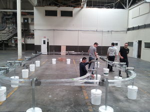
1/12th Scale Track Design
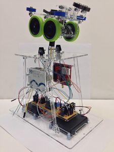
1/12th Scale Pod Design
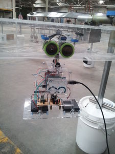
1/12th Scale Pod on Rail


One of the biggest challenges in our design was having the line follower interface with the rest of the system components. Having an understanding of how FreeRTOS manages multiple tasks during operation was critical to having the system operate properly. Very early on in the project, it was decided that the system would take advantage of the shared queues concept to do communication between various tasks. Surprisingly, getting the pods to seem autonomous was the easy part. The path generating algorithm, Dijkstra, was fairly straight forward to use and very easy to interface with the rest of our system.
This project also enabled our members to learn more about writing serial bus drivers, using a real-time operating system, working with wireless communications, and algorithms that enable autonomous control. As mentioned earlier, we contributed to a much larger SJSU project called the Spartan Superway and this project was just the initial step in creating a fully autonomous transit network. There is much more that must be done going forward. For example, there is a need for collision avoidance protocols in the system, this can be achieved by allowing the pods in the system to communicate and determine which has the right of away. Alternatively, a master computer could oversee the operation of the entire network and decide which pods have the right of way at a junction.
We concluded our project by having the opportunity to present as part of an exhibit at Maker Faire in San Mateo on May 17th and 18th. It was both exciting and rewarding as many of our audiences were thoroughly impressed by the amount of work the SJSU Engineering students accomplished. The control’s team had attracted the most attention and it was often the case that the audiences came to our demo first. This project was a great way to end our SJSU college careers as it encompassed a majority of the topics learned in the Computer Engineering program, and it really tested our abilities to work as part of a team of multi-disciplinary engineering students.
Project Video
Upload a video of your project and post the link here.
Project Source Code
References
Acknowledgement
We would like to give thanks to the following people for their contributions towards the project.
- Preet Kang: For teaching us about the FreeRTOS and various serial communication busses that became the basis of our project.
- Keith Perry: Our project advisor, without whom we may not have known about this project. Also, for pushing us to be the best that we can be.
- Marjo Mallari: Another member of our Senior Project group, she worked on our path generating algorithm (Dijkstra).
- Cory Ostermann: Mechanical Engineering student who worked closely with us on the 1/12th Scale Model implementation.
- Barry Swenson: For providing us with an offsite location to work on the project.
- Dr Furman (ME dept): For allowing us to join the Spartan Superway Project and guiding us throughout the process.
- Ron Swenson, Bryan Burlingame, the rest of the Spartan Superway Team, and the various sponsors of our project, Thank You!
References Used
- [1] FreeRTOS website: FreeRTOS Homepage
- [2] SNAP device Reference Manual: PDF link
- [3] Portal Reference Manual: PDF link