Difference between revisions of "S14: Autonomous Control System"
Proj user8 (talk | contribs) (→Conclusion) |
Proj user8 (talk | contribs) (→Abstract) |
||
| Line 16: | Line 16: | ||
== Abstract == | == Abstract == | ||
| − | + | SJSU’s Spartan Superway will provide an automated, solar-powered PRT system. The objective of this particular project, within the Superway initiative, was to develop an autonomous control system for all pods (vehicles) using a wireless mesh architecture. The control system is to communicate with a central computer that would send new destinations to pods as they arrive at a station. The pods are to navigate the track system autonomously and communicate updates on their location to the master computer. This project is part of the larger SJSU Spartan Superway, more information on the project can be found at: | |
| − | + | [http://www.engr.sjsu.edu/smssv/ Spartan Superway Homepage] | |
| − | |||
| − | |||
| − | SJSU’s Spartan Superway will provide an automated, solar-powered PRT system. The objective of this particular project within the Superway initiative was to develop | ||
| − | |||
| − | This | ||
== Objectives & Introduction == | == Objectives & Introduction == | ||
Revision as of 20:09, 22 May 2014
Contents
Grading Criteria
- How well is Software & Hardware Design described?
- How well can this report be used to reproduce this project?
- Code Quality
- Overall Report Quality:
- Software Block Diagrams
- Hardware Block Diagrams
- Schematic Quality
- Quality of technical challenges and solutions adopted.
Spartan Superway Control System

Abstract
SJSU’s Spartan Superway will provide an automated, solar-powered PRT system. The objective of this particular project, within the Superway initiative, was to develop an autonomous control system for all pods (vehicles) using a wireless mesh architecture. The control system is to communicate with a central computer that would send new destinations to pods as they arrive at a station. The pods are to navigate the track system autonomously and communicate updates on their location to the master computer. This project is part of the larger SJSU Spartan Superway, more information on the project can be found at: Spartan Superway Homepage
Objectives & Introduction
Show list of your objectives. This section includes the high level details of your project. You can write about the various sensors or peripherals you used to get your project completed.
Team Members & Responsibilities
- Elizabeth Poche
- Driver & Line Follower Development
- Eriberto Velazquez
- FreeRTOS Software Design
- Trent Smith
- SNAP Communication
Schedule
Show a simple table or figures that show your scheduled as planned before you started working on the project. Then in another table column, write down the actual schedule so that readers can see the planned vs. actual goals. The point of the schedule is for readers to assess how to pace themselves if they are doing a similar project.
| Week# | Date | Task | Actual |
|---|---|---|---|
| 1 | 3/28 |
|
|
| 2 | 4/4 |
|
|
| 3 | 4/11 |
|
|
| 4 | 4/18 |
|
|
| 5 | 4/25 |
|
|
| 6 | 5/2 |
|
|
| 7 | 5/9 |
|
|
| 8 | 5/16 |
|
|
Parts List & Cost
Give a simple list of the cost of your project broken down by components. Do not write long stories here.
| Part | Quantity | Cost Each | Total Cost |
|---|---|---|---|
| Pod Chassis | 3 | $15 | $45 |
| H-Bridge | 3 | $3.64 | $10.92 |
| IR LED/Sensor | 15 | $0.58 | $8.69 |
| DC Battery | 3 | $23.55 | $70.65 |
| SJOne Board | 3 | $60 | $180 |
Design & Implementation
The design section can go over your hardware and software design. Organize this section using sub-sections that go over your design and implementation.
Hardware Design
Discuss your hardware design here. Show detailed schematics, and the interface here.
Superway’s control system employed known architectures used in many systems, such as peer-to-peer and distributed systems. These architectures were utilized in Superway’s design and modified to fit with our system. Overall, the system had a wireless mesh network architecture. The state machine represented the center of the mesh which connected communication between peripherals. The peripherals received instructions from the master controller and communicated necessary information to the master controller. Shown in Figure 4.2, the state machine was the central server that had access to all pods through SNAP wireless and had the authority to override any current commands and other controllers.
The hardware components of this project consisted of the SJOne Board, H-Bridge, mux, IR LEDs, and voltage converters. The SJone Board allows the pod to have a state machine to control the direction of the pod. The H-Bridge controls the left and right motors. The mux changes the state of the pods direction. IR LEDs track the line. Figure 1 shows the pinout of the H-bridge.
Figure 1 shows the SJOne Board pinout and how it is connected to a 153 multiplexer gate and 04 gate. The SJOne board uses a and b to choose which type of direction the pod should perform when reaching a node; straight, right turn, or stop. Figure 2 and 3 show the logic of the mux.
Figure 1: SJOne Board Pinout

Figure 2: Mux Logic

Table 1: Mux Logic Table

Figure 3 shows the pinout of the IR LEDs. Right and Left outputs are connected through an 04 gate to the mux and SJOne board.
Figure 3: IR LED Pinout

Figure 4: H-Bridge Pinout


Hardware Interface
In this section, you can describe how your hardware communicates, such as which BUSes used. You can discuss your driver implementation here, such that the Software Design section is isolated to talk about high level workings rather than inner working of your project.
To implement the pod system, small steps had to be taken to avoid periods if the
design does not work and cannot isolate the issue. In the event the design did not work
there was a previous design that worked. The design process started with a baseline using
a simple prototype. A simple line follower was built to learn the basics of the line
follower. To make the pod intelligent, a microprocessor was integrated. To get the line
follower working, hardware and software were combined. Hardware controlled the pod,
which followed the line and software gave user the control over the pod’s path traversal.
The line follower followed a line using IR emitters and receivers, which pointed
down, toward the ground. The emitter sent a constant IR signal. If the signal hit white
part of the track layout, the signal reflected, and if the signal hit black tape, the signal did
not reflect. Using this technology, Left and Right IR signals were used to follow the line.
LLeft and RRight were signals to inform the microprocessor that the pod has reached a
node.
Figure 4.5 shows the fork, merge, and station design of the line. When the pod reached a node it tok a new instruction from the state machine to either continue straight, turn right, or stop. The pod had four modes it can be in: straight mode, right mode, RC mode, and software mode, shown in Table 4.A. If the pod was instructed to continue straight through node, the software chose straight mode and turned on both wheels until either Left AND Right, OR LLeft AND Left AND RRight, OR LLeft AND Right AND RRight signals saw white. If the pod was instructed to turn right, the software chose right mode and turned off the right wheel and turned on the left wheel until LLeft AND Left OR LLeft AND Right signals saw white. If the pod was instructed to stop, the software went into RC mode and since the station was black, the sensors did not see a reflection and therefor stopped both wheels. The pod remained stopped and waited for the next instruction. Figure 4.5 shows the station design of the tape. Each black block represented a node where the pod received the next instruction from the instructions queue.
Figure 4.5: Station Design Other hardware components of the pod consisted of the SJOne Board microcontroller, L298 H-bridge, logic gates, and voltage converters. Figure 4.6 shows the hardware’s logic.
Software Design
The Superway Control system takes advantage of the FreeRTOS’ multi-tasking capabilities. The control system is divided into multiple tasks, each having their own separate responsibilities.
State Machine Task
This is the central component within the system, it communicates with all other tasks in the system via shared queues. It is responsible for transitioning the vehicle from a ready state, in which it is ready to receive new directions, to a traveling state. The states are as follows:
- Startup – This is the initial state where all initializations occur.
- Ready – SM remains in this state whilst no new destination has been received by the pod (vehicle. It signifies that the pod is ready to begin a new route and is awaiting a new destination. If a new destination arrives, the state machine sends the starting location and destination to the path generating algorithm and then transitions to the next state, receiveDir.
- ReceiveDir – Here, the state machine receives a list of directions, from the Dijkstra algorithm, that will help the pod navigate the track system and reach its new destination, once all directions are received it transitions to the next state, load.
- Load – Currently, this state does nothing but transition into the “travel” state. It remains in the code for future progress on the control system, where a loading of passengers sequence must be simulated for a real transit system.
- Travel – This is the main state the state machine will remain in during navigation. During this state, the state machine communicates with the line follower task and sends the instructions necessary for navigation. This state also updates the master computer with location information. Once the pod reaches its destination, the system transitions into the arrive state.
- Arrive – In this state, if the line follower sends a signal, it tells the state machine that the pod has successfully reached its destination and a delay is put in place to simulate the offloading of passengers. Now the system returns to the ready state.
- Error – While not used in this implementation the error state remains in the control system’s state machine for future use. This would become the default state when initializations fail or any other state fails.

Pathing Task
This task contains the path generating algorithm, Dijkstra’s shortest-path algorithm. It communicates directly with the State machine task at the beginning of a new route. This task is responsible for determining the set of instructions the pod must follow in order to reach its destination from its current location. When a path is determined, a set of instructions corresponding to which turns must be made and at what points is generated and then passed back to the state machine.
Line Follower Task
This task has the sole responsibility of controlling the motors and reading from the Infra-red sensors that keep the pod on the track. The task also communicates with the State Machine in order to receive the list of instructions that it must execute as it traverses the track. As a node is approached all five IR sensors are triggered, at this time the line follower task must read the next instruction in the list. These instructions will tell the line follower to go straight, make a turn, or stop at the given node. Once the destination is reached, denoted by a special character at the end of the list, the line follower task sends a signal to the state machine task.
Wireless Task
This task is responsible for communicating between the master computer (laptop) and the state machine. Currently, this task is responsible for supplying the state machine with the new destination scheduled by the master computer. It is also responsible for sending the master computer regular updates on the pod’s location as it traverses the track. Communication is done via a wireless SNAP module (RF) with the master computer. The SNAP RF2466PC1 module uses UART to communicate with the control system and relay new messages received. The wireless task on the SJONE was programmed using C++, while the RF2466PC1 script as well as the portal script were written using Python and snappy script. Key features:
- Updated time - updates the RTC of the pods SJONE with the current time from the master.
- Register - registers the pod with the master before the pod can change operate.
- Update - the pod sends the current location, tick count, current destination, and time since last tick to the master.
- Get Destination - the pod requests a new destination from the master based on current location.
Implementation
This section includes implementation, but again, not the details, just the high level. For example, you can list the steps it takes to communicate over a sensor, or the steps needed to write a page of memory onto SPI Flash. You can include sub-sections for each of your component implementation.
Testing & Technical Challenges
Describe the challenges of your project. What advise would you give yourself or someone else if your project can be started from scratch again? Make a smooth transition to testing section and described what it took to test your project.
Include sub-sections that list out a problem and solution, such as:
Design Constraints
The design constraints for this project were: initially, there was no track to test the software on. The solution was to create a pod that would follow a black line on paper. This made building the track simple and cheap. The main goal was to make the pods intelligently follow the track.
Design Problems and Challenges
The component that was the most difficult to design program were the pod’s movements. The parts purchased were very inexpensive and caused difficulties later in making the pod more accurate. Using hardware to have the pod follow the line was simple and reliable. Using software to control the pod to follow the line became a challenge because the objective was to make the software as efficient and reliable as the hardware. During the first test phases of the line follower, a white flexible mat was used as a track and black electrical tape was used as the line. However, the tape stretched and caused the mat to have ripples in it. When the pod traveled over the ripples, it needed a certain amount speed to travel over the bump. If the speed was too fast, the pod would go off track. Another problem was the tape on the track. When the pod made a right turn, it went off track. The electrical tape was black but it still had a little of reflection. A less reflective tape was tested and improved slightly. Non-reflective tape was also tested but did not improve the performance of the pod turning right and continuing straight.
Design Solutions and Trade-Offs
Since the first design track mat had problems with the ripples, another track was made using particle board and the same tape. This allowed the pod to go slower and lower the chances of the pod getting off track. Software controlling the line following was slower than the hardware. Hardware was used to control the line following and software for the decision making at each node. The hardware followed the line decently but software could have made it more intelligent to follow the line. This work was not pursued because the main focus of this project was to build a control system, not a line follower. The line follower was used only to provide a visual for our software-based control system.
System Testing
Testing for the control system was done at first by testing the individual tasks, then as integration of the system occurred. Each time components were integrated into the system, testing was done to verify that communication between them worked properly. The components and their testing procedures are listed below.
Conclusion
Conclude your project here. You can recap your testing and problems. You should address the "so what" part here to indicate what you ultimately learnt from this project. How has this project increased your knowledge?
Taking part in the Spartan Superway project as part of the Controls sub-team was a great experience for us. While the focus of our project was mainly on the software side of the control system, we did have the opportunity to work with Mechanical Engineering students in other parts of the project including work done on an alternative control system for a 1/12th scale model of our track and a 1/12th Scale model of the pods (vehicles) that run on a rail, see figures below.
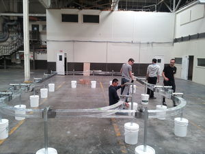
1/12th Scale Track Design
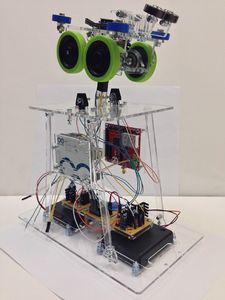
1/12th Scale Pod Design
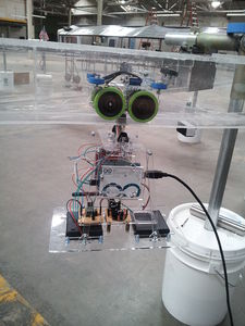
1/12th Scale Pod on Rail


One of the biggest challenges in our design was having the line follower interface with the rest of the system components. Having an understanding of how FreeRTOS manages multiple tasks during operation was critical to having the system operate properly. Very early on in the project, it was decided that the system would take advantage of the shared queues concept to do communication between various tasks. Surprisingly, getting the pods to seem autonomous was the easy part. The path generating algorithm, Dijkstra, was fairly straight forward to use and very easy to interface with the rest of our system.
This project also enabled our members to learn more about writing serial bus drivers, using a real-time operating system, working with wireless communications, and algorithms that enable autonomous control. As mentioned earlier, we contributed to a much larger SJSU project called the Spartan Superway and this project was just the initial step in creating a fully autonomous transit network. There is much more that must be done going forward. For example, there is a need for collision avoidance protocols in the system, this can be achieved by allowing the pods in the system to communicate and determine which has the right of away. Alternatively, a master computer could oversee the operation of the entire network and decide which pods have the right of way at a junction.
We concluded our project by having the opportunity to present as part of an exhibit at Maker Faire in San Mateo on May 17th and 18th. It was both exciting and rewarding as many of our audiences were thoroughly impressed by the amount of work the SJSU Engineering students accomplished. The control’s team had attracted the most attention and it was often the case that the audiences came to our demo first. This project was a great way to end our SJSU college careers as it encompassed a majority of the topics learned in the Computer Engineering program, and it really tested our abilities to work as part of a team of multi-disciplinary engineering students.
Project Video
Upload a video of your project and post the link here.
Project Source Code
Send me your zipped source code and I will upload this to SourceForge and link it for you.
References
Acknowledgement
Any acknowledgement that you may wish to provide can be included here.
References Used
List any references used in project.
Appendix
You can list the references you used.