Difference between revisions of "S13: Garage Parking Aid"
(→Acknowledgement) |
(→Hardware Interface) |
||
| Line 185: | Line 185: | ||
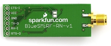
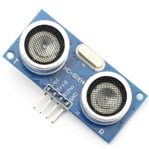
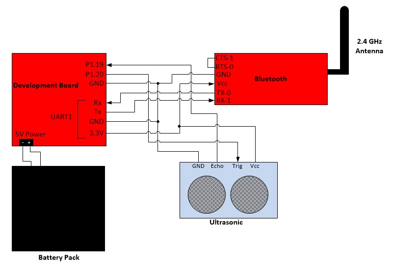
Hardware Communication: The development board is connected to the bluetooth chip and ultrasonic receiver/transmitter. The bluetooth receives data through the pins and transmits the data over bluetooth. The ultrasonic receives a trigger signal through the pins then sends an ultrasonic pulse. When the echo is read back it will send an echo pulse back to the board. The battery gives 5V power to development board and ultrasonic. | Hardware Communication: The development board is connected to the bluetooth chip and ultrasonic receiver/transmitter. The bluetooth receives data through the pins and transmits the data over bluetooth. The ultrasonic receives a trigger signal through the pins then sends an ultrasonic pulse. When the echo is read back it will send an echo pulse back to the board. The battery gives 5V power to development board and ultrasonic. | ||
| + | |||
| + | The UART2 driver is made from one object of the class Uart2. To prevent copies of the object, the constructor of Uart2 class is private. To use UART2, the object must be found using getInstance(). | ||
=== Software Design === | === Software Design === | ||
Revision as of 03:01, 22 May 2013
Contents
Grading Criteria
- How well is Software & Hardware Design described?
- How well can this report be used to reproduce this project?
- Code Quality
- Overall Report Quality:
- Software Block Diagrams
- Hardware Block Diagrams
- Schematic Quality
- Quality of technical challenges and solutions adopted.
Project Title
Garage Parking Aid
Abstract
This section should be a couple lines to describe what your project does.
The purpose of this project is to aid when parking a car. This device will send to an Android phone the distance between the car and an obstacle.
Objectives & Introduction
Show list of your objectives. This section includes the high level details of your project. You can write about the various sensors or peripherals you used to get your project completed.
The purpose of this project is to build a parking aid that will measure the distance between an object and a car and send the data to the user's Android phone. An ultrasonic transmitter/receiver is used to measure the distance and bluetooth is used to send data to the Andoid phone.
Objectives:
- Measure distance and display on computer screen
- Send data over bluetooth
Team Members & Responsibilities
- Elizabeth
- Create UART2 driver
- Wire peripherals
- Send messages with Bluetooth
- Tian
- Create Android app
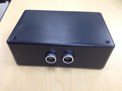
- Assemble project into a box
- Configure ultrasonic distance meter
Schedule
| Week Number | Planned Items | Actual |
|---|---|---|
| 1 |
|
|
| 2 |
|
|
| 3 |
|
|
| 4 |
|
|
| 5 |
|
|
Parts List & Cost
| Parts | Cost |
|---|---|
| SJ One Board | $65 |
| Bluetooth | $0 |
| 2.4 GHz Antenna | $5 |
| Ultrasonic transmitter and receiver | $10 |
| Blackbox | $0 |
| Wire | $10 |
| Batteries | $7 |
| Total: | $97 |
Design & Implementation
The design section can go over your hardware and software design. Organize this section using sub-sections that go over your design and implementation.
Hardware Design
Discuss your hardware design here. Show detailed schematics, and the interface here.
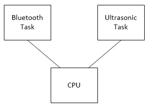
The Bluetooth device is connected to UART1 and the ultrasonic device is connected to GPIO. To communicate with the Bluetooth, the program sends data to UART1 and then is sent to bluetooth. To comunicate with the ultrasonic, the program sends and receives data from the board's pins P1.19 and P1.20.
Another option to capture the time of the ultrasonic's pulse is to program the GPIO pins to be PWM and capture. The PWM pin will output a pulse to the ultrasonic and the ultrasonic will send an ultrasonic pulse. When it receives an echo of the pulse it will send a pulse to the caputure pin. When the capture pin receives a change in voltage, it will store the time into a designated register.
Hardware Interface
In this section, you can describe how your hardware communicates, such as which BUSes used. You can discuss your driver implementation here, such that the Software Design section is isolated to talk about high level workings rather than inner working of your project.
Hardware Communication: The development board is connected to the bluetooth chip and ultrasonic receiver/transmitter. The bluetooth receives data through the pins and transmits the data over bluetooth. The ultrasonic receives a trigger signal through the pins then sends an ultrasonic pulse. When the echo is read back it will send an echo pulse back to the board. The battery gives 5V power to development board and ultrasonic.
The UART2 driver is made from one object of the class Uart2. To prevent copies of the object, the constructor of Uart2 class is private. To use UART2, the object must be found using getInstance().
Software Design
Show your software design. For example, if you are designing an MP3 Player, show the tasks that you are using, and what they are doing at a high level. Do not show the details of the code. For example, do not show exact code, but you may show psuedocode and fragments of code. Keep in mind that you are showing DESIGN of your software, not the inner workings of it.
Implementation
This section includes implementation, but again, not the details, just the high level. For example, you can list the steps it takes to communicate over a sensor, or the steps needed to write a page of memory onto SPI Flash. You can include sub-sections for each of your component implementation.
Testing & Technical Challenges
Describe the challenges of your project. What advise would you give yourself or someone else if your project can be started from scratch again? Make a smooth transition to testing section and described what it took to test your project.
Include sub-sections that list out a problem and solution, such as:
Wifi Connection Issues
Many wifi connection issues were encountered. To solve this problem, a dedicated task was created to re-connect to wifi if the connection was ever lost.
Conclusion
Conclude your project here. You can recap your testing and problems. You should address the "so what" part here to indicate what you ultimately learnt from this project. How has this project increased your knowledge?
Project Video
Upload a video of your project and post the link here.
Project Source Code
Send me your zipped source code and I will upload this to SourceForge and link it for you.
References
Acknowledgement
- Preet Kang
- Dr. Haluk Ozemek
References Used
List any references used in project.
- https://www.sparkfun.com/products/158
- http://www.micropik.com/PDF/HCSR04.pdf
- https://s3-ap-northeast-1.amazonaws.com/sain-amzn/20/20-019-100/HC-SR04.rar
Appendix
You can list the references you used.
