S13: 2D Plotter
Contents
2D Plotter
2D Plotter

Abstract
The following text describes the design, programming, and testing of a simple plotter. A plotter is a computer output device similar to a printer that is designed to print a design based on vectors.
This plotter was developed as the final project for the Embedded Systems class (CmpE146) at San Jose State University, California. It consists of a wooden chassis, two stepper motors to position the print head, a print head using an electromagnet to lift or lower the pen, and an ARM-based controller board running FreeRTOS.
To test the plotter, a set of simple geometric shapes will be printed once the device has been completed.
Objectives & Introduction
The purpose of this project is to design a simple 2D plotter that can then be modified to serve as a CNC router, a laser cutter, or any other vector-based 2D output device. In addition, the design of the plotter is intended as a preliminary step towards the design of a 3D printer. The experience from the design of the plotter will allow us to asses which of our ideas are current ideas can be realized with the hardware and software options available to use at the current time.
One main objective of the design is to reuse as many existing components as possible. For example, belts, gears, and motors from old inkjet printers have been collected to be used in this design.
As far as the operation of the plotter is concerned, the objectives of this project are:
1. Use the ARM-based SJSUONE board to control all necessary hardware through GPIOs.
2. Design a wooden enclosure for the hardware.
3. Create a program that allows control of the hardware to create some useful output.
Team Members & Responsibilities
- Matthias
- Hardware Development
- William
- Driver Development
- Sergey
- Wiki and Documentation
Schedule
| Week | Planned Tasks | Actual Tasks |
|---|---|---|
| 1 |
|
|
| 2 |
|
|
| 3 |
|
|
| 4 |
|
|
| 5 |
|
|
Parts List & Cost
| Parts | Cost |
|---|---|
| 2012 SJ One Board | $65 |
| 3 x Nema 17 Stepper Motors | $33.20 |
| 4 x Steel shapes, round | $14.76 |
| 3 x Stepper Motor Controller | $12.39 |
| Power supply | $10 |
| New wood (various sizes) | $8.94 |
| Breadboard | $7 |
| 6 x Hollow metal tubes | $4.74 |
| 4 to 16 decoder | $3 |
| Old wood | $0 |
| Screws | $0 |
| Old printer gears | $0 |
| Old printer belts | $0 |
| Wires | $0 |
| Glue | $0 |
| Total: | $159.03 |
Design & Implementation
In designing the plotter, three main components need to be considered. These are the mechanical design, which consists of the chassis, motors and timing belts, and rails to position the print head on a two-dimensional grid, the electronics to control the stepper motors and any limit switches used to ensure proper position, and the software to communicate with the hardware in order to produce the expected output.</ br>
Hardware Design
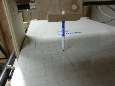
The plotter base consists of a 48 cm x 48 cm x4.5 cm enclosure (see Illustration 1) that holds the motors, the mechanical components to move the timing belts, and the electronic components.
Each of the two motor guides consist of one NEMA 17 stepper motor, a large gear to hold the timing belt, and a smaller gear to position the timing belt near the top of the motor guide. To mount the motor, a large hole for the gear shaft and two small screw holes to mound the motor were drilled on one side. The gears can be attached using screws. For this particular plotter, special pins to hold plastic hears were glued into small holes. These pins were salvaged form an old inkjet printer.
The rails to move the print head are attached to columns on the side of the printer. These rails were cut to fit from 8 mm metal bars and should be placed in parallel on opposite sides of the printer for each of the two directions. A thin opening is cut in the base where the timing belt is located. This will be the point where the two sliders are mounted to the timing belts.
The slider is currently comprised of a block of wood with a fitting guide hole. Caution should be taken that the guide block fits snugly yet can move without too much friction. Ideally, these wooden blocks would be replaced with linear ball bearings. If the rails are not completely parallel, it might be necessary to cut the guide slider on one side so that it rests loosely on the rail. This involves cutting the bottom of the slider with a saw so that the hole is turned into a half-circular groove.
Two thin wooden boards with a cut-out center are mounted crisscross on the sliders. The pen mounting mechanism is then positioned in the intersection of the two boards. It should move smoothly as the sliders are positioned in the x and the y directions. For this plotter, an empty wire-wrapping cable spool was cut in half and placed in the opening. To re-attach the two halves, a 3” strip of thin cardboard was rolled up and pushed inside the spool, holding the two pieces together. An electro-magnet on top of this assembly is used to lift or lower the pen. For this purpose, a Sharpie is cut in half, and the opening is glued shut with a metallic top (in this case the head of a large screw).</ br>
Hardware Interface
The stepper motor are controlled using two STMicroelectronics L298N Full-bridge motor drivers, which are attached to the SJSU-One ARM-based controller board. </ br>
The L298N can control a 4-wire bipolar stepper motor using a 4-bit binary input. The required sequence is 4’b0001, 4’b0010’ 4’b0100’ and 4’b1000 for clockwise operation. Reversing the inputs will produce a counter-clockwise rotation. An input of 4’b1111 or 4’b0000 will not affect the current position of the stepper motor. Therefore, it is possible to control up to four motors with a 4 of 16 decoder such as a 74LS154. We are currently using a 4-of-16 decoder and three stepper motor controllers to test the hardware performance with the z-axis motor of the 3D printer in mind. However, the current hardware only does need 2 motors.</ br>
Software Design
Show your software design. For example, if you are designing an MP3 Player, show the tasks that you are using, and what they are doing at a high level. Do not show the details of the code. For example, do not show exact code, but you may show psuedocode and fragments of code. Keep in mind that you are showing DESIGN of your software, not the inner workings of it.
Implementation
This section includes implementation, but again, not the details, just the high level. For example, you can list the steps it takes to communicate over a sensor, or the steps needed to write a page of memory onto SPI Flash. You can include sub-sections for each of your component implementation.
Testing & Technical Challenges
Describe the challenges of your project. What advise would you give yourself or someone else if your project can be started from scratch again? Make a smooth transition to testing section and described what it took to test your project.
Include sub-sections that list out a problem and solution, such as:
Wifi Connection Issues
Many wifi connection issues were encountered. To solve this problem, a dedicated task was created to re-connect to wifi if the connection was ever lost.
Conclusion
Conclude your project here. You can recap your testing and problems. You should address the "so what" part here to indicate what you ultimately learnt from this project. How has this project increased your knowledge?
Project Video
Upload a video of your project and post the link here.
Project Source Code
Send me your zipped source code and I will upload this to SourceForge and link it for you.
References
Acknowledgement
None. Preet Kang and Dr. Ozemek did not really help us. They just graded us. If only they spent more time helping us rather than grading us. Just saying.
References Used
3D printing. (2013). Retrieved from http://en.wikipedia.org/wiki/3D_printing
Benchoff, B. (2012). Print huge stuff with the Makerbot Replicator. Retrieved from http://hackaday.com/2012/01/09/print-huge-stuff-with-the-makerbot-replicator/
Chace, Z. (2013). 3-D Printing Is (Kind Of) A Big Deal. Retrieved from http://www.npr.org/blogs/money/2013/01/04/168627298/3-d-printing-is-kind-of-a-big-deal
Deckard, C. (1986). Method and apparatus for producing parts by selective sintering. United States. 4863538. Austin, Texas: Board of Regents, The University of Texas System
Evans, Brian. (2012). The Sciene and Art of 3D Printing. New York, NY: Springer Science + Business Media.
Eveleth, R. (2012). Our three-dimensional future: how 3D printing will shape the global economy. Retrieved from http://www.smartplanet.com/blog/report/our-three-dimensional-future-how-3d-printing-will-shape-the-global-economy/559
Kelly, James F. and Hood-Daniel, P. (2011). Printing in Plastic: Build Your Own 3D Printer. New York, NY: Springer Science + Business Media.
Hartmann, K. et al. (1994). Robot-Assisted Shape Deposition Manufacturing. San Diego, CA: Proceedings of the 1994 IEEE International Conference on Robotics and Automation
Hotz, R. (2012). Printing Evolves: An Inkjet for Living Tissue. Retrieved from http://online.wsj.com/article/SB10000872396390443816804578002101200151098.html
RepRap. (2013). Retrieved from http://www.reprap.org/wiki/Main_Page
RepRap Options. (2013). Retrieved from http://reprap.org/wiki/RepRap_Options
Appendix
You can list the references you used.