S12: Eyes-Free GPS
Contents
Project Title
Eyes-Free GPS
Abstract
This project is a stepping stone for an Eye’s Free GPS device. An Eyes-Free GPS device allows the user to enjoy the benefits of GPS at the ease of only 1 button and a microphone for user input, and audio out for the device output. Focus is not on the actual device itself, but more of where this 1 button concept can be installed (a car or mp3 player). In this project, the longitude and latitude of every building at San Jose State University will be recorded. Pressing the button will alert the user via audio clip what building they are currently standing next to. The goal is to become more familiar with the FreeRTOS operating system and the LPC2148 Microcontroller.
Objectives & Introduction
This project uses the LPC 2148 Microcontroller that is equipped with FreeRTOS which is in open source operating system. FreeRTOS is used not only because of the small memory footprint but also because it can context switch between tasks and execute these tasks at very high speeds. On the microcontroller, since the UART0 port is already used for the console window (debugging purposes), the UART1 port is used to receive data from the GPS module. Below are the 4 main objectives of this project.
- Initialize UART1 driver on LPC and set up a pin to get data from the GPS
- Parse the data to grab only the longitude and latitude coordinates and store the numbers in a temporary container
- Set up a FreeRTOS task that executes whenever the button is pushed
- This task plays a specific sound clip depending on the coordinates
Team Members
Michael Mariani
Roles and Responsibilities
There is only 1 team member (myself), so I got the opportunity to play all of the roles. I gathered the hardware, connected up the GPS with the microcontroller/audio board, wrote all of the software, and was the tester and debugger. Some might say its bad for the designer and the tester to be the same person because it will be hard to catch the mistakes. I took it as a learning experience.
Parts List & Cost
| Parts | Cost |
|---|---|
| ARM7-NXP LPC2148 Microcontroller | $60 |
| MP3 Development Board | $60 |
| GlobalSat ET-318 GPS Engine Board | $40 |
| Jumper Wires | $6 |
| SD Card | $10 |
| Total: | $176 |
Design & Implementation
Unfortunately, poor time management caused the project to be incomplete by the time it was due. This hardware and software design that follows is subject to change during testing and debugging stages, however, this documentation is a good place to start.
Hardware Design
The 3 main components are the LPC2148 Microcontroller, the MP3 Development , and the ET-318 GPS Engine Board.
GlobalSat ET-318 GPS Engine Board
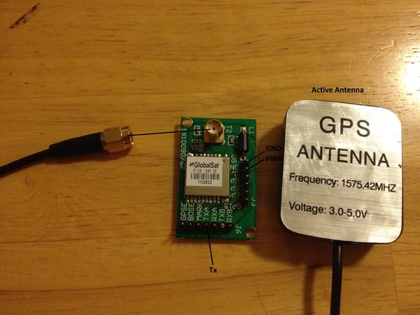
GPS chips send data in certain formats. If no control is sent to the GPS, the default data format is returned. If displayed to screen, the data would look like this: $GPGGA,hhmmss.ss,llll.ll,a,yyyyy.yy,a,x,xx,x.x,x.x,M,x.x,M,x.x,xxxx (where llll.ll and yyyy.yy and latitude and longitude respectively). Below if a picture of the GPS module with the pins used.
This GPS module is not the best choice for the project if an actual device is what you want. The antenna is very long and bulky. However, if installed in a car, the antenna can run internally throughout the whole car. Detailed schematics and datasheet can be found here: http://www.investigacion.frc.utn.edu.ar/sensores/Equipamiento/gps/ET-318-user-manual-V2.0.pdf . Other GPS data formats can be found here: http://aprs.gids.nl/nmea/ .
Microcontroller + Audio Board
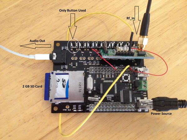
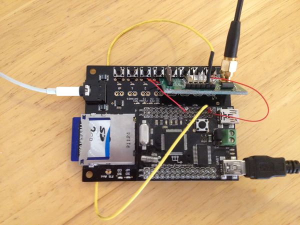
As in the MP3 lab, the microcontroller sits right on top of the audio board. All of the audio clips are stored in the SD card. When the microcontroller knows what the closest building is (for example: building 12), then it tells the audio board to play song 12.
Above in figure , the yellow wire is giving the GPS module 3.3V. The red wire on the right is ground and the red wire on the left is Rx (Tx from the GPS). As for audio out, the cheapest way was just to plug in headphones but a speaker can go there as well (or connect the audio out to your vehicle's audio system). Detailed schematics of the microconotroller can be found here: https://sjvalley.com/shop/images/stories/Schematic/LPC2148Plugin%20Schematics.pdf . Detailed schematics of the audio board can be found here: https://sjvalley.com/shop/images/stories/Schematic/Audio%20Board%20Schematics.pdf .
Hardware Interface
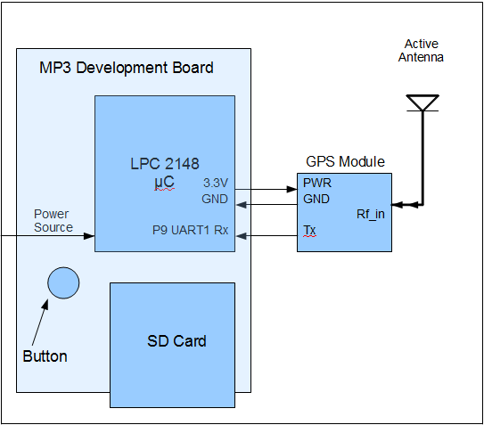
The connections in this project are very straight forward. The magic is in the software, not the hardware. Below is a block diagram of how everything is connected.
UART1 is used for receiving GPS data and UART0 (usb to computer) is used to display characters on the console (for testing and debugging).
UART1 Initialization
When the power is turned on, the first thing FreeRTOS does is initialize the the UART1 driver. When the function is called it first clears the 16-19th bits of PINSEL0 and then sets them to 0101 (this control is for uart1 RX and TX). According to the datasheet, the UART1 RX port is activated through pin 9 (P0.9). Tx is pin 8 but this pin is not used since no data gets sent to the GPS. Below is some source code showing the initialization process.
PINSEL0 &= ~(0xF << 16); //unset bits 19-16
PINSEL0 |= (5 << 16); //sets bits 19-16 to 0101 (5 in binary)
After the pin is selected, the UART1 control registers need to be set. These include:
U1LCR (UART1 Line Control Register): 7th bit is set to 1 so baud rate can be modified.
U1DLL (Divisor Latch LSB) : set to PCLK/(16*baudRate) (from lab 1)
U1DLM (Divisor Latch MSB) : set to 0
Next, the 7th bit in U1LCR gets set back to 1 and the rest of the bits get set in order to have an 8-bit word length, 1 stop bit, and no parity. Following this is all in software until the button is pushed. This button causes an interrupt. The microcontroller stops what it is doing (constantly updating the currentLocation buffer with new coordinates) and sends a copy of the current location to all of the buildings (this is still in software). When the closest building is calculated and matched up to a certain mp3 on the SD card, an audio clip is played the same way it is played in the MP3 lab.
Software Implementation
The software objectives can be broken into 3 main tasks:
- Parse GPS data to find coordinates
- A building class that has "Distance from current Location" as one of the fields
- A task to play an MP3
Parsing
All the fields within the GPS data string are separated by commas. Below is some pseudocode on how the data can be parsed.
while (NULL != token)
{
  token = strtok(0, "\n");
  while(NULL != strtok()
  {
    int time = strtok(datastr, ",");
  }
  float latitude = atof(strtok(datastr, ","));
}
float longitude = atof(strtok(datastr, ","));
The function strtok returns a pointer to the next token within the string. The first parameter is the string and the second parameter is the deliminator. The way the above code works is by first parsing the time stamp. This is the first set of data after the format header ($GPGGA). Once the token reaches a comma the nested while loop is complete. The next numbers in the GPS data is the latitude. It gets parsed and stored. Following that is the longitude which of course is separated by another comma.
Building Class
An easier way to implement this is to just immediately find the distance between the current location and all of the points on all of the buildings and then play a song based off which point the current location is closest to. Instead of doing that, since most programming languages these days are object oriented, why not have some practice? It will making debugging easier as well. In C there are no classes so a struct is constructed instead:
struct building {
  int ID;
  float p1;
  float p2;
  float p3;
  float p4;
  float distFromCL;
  audioFlag = 0;
};
Every struct has a building ID (so there aren't magic coordinate numbers everywhere, these ID numbers can be mapped up to the map of SJSU in the appendix). Every struct has AT LEAST 4 points (1 point per building was not accurate enough). Every struct has a distance from current location (which gets updated when button is pushed). Every struct has an audio play flag that is set to 1 when distFromCL is smallest (setting to 1 will alert the mp3 task to play that song).
MP3 Task
This task is in charge of taking in the building ID number and playing a song based off of that ID number. For example, building 12 is the closest building so the audioflag within that stuct gets set to 1. This is a signal that that specific struct is the closest building. The ID field (12) gets sent to the MP3 task which then chooses the 12th song in the SD Card and streams it continuously to the MP3 decoder. Below is how the task is created in main:
xTaskCreate( mp3Task, (signed char*)"MP3", STACK_BYTES(1024*6), &SysHandles, PRIORITY_HIGH, &SysHandles.task.mp3)
Since this is the only task after the interupt, priority is set to high to ensure it gets executed quickly and thoroughly.
Software Design
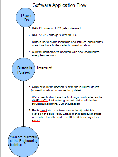
This diagram is small because user interaction is at a minimum.
Testing & Technical Challenges
There were major technical challenges that were encountered with the GPS module. The UART1 port reads all zeros at times and all garbage characters at other times. These bugs were not worked out because of lack of time. The next major difficult part was to play a specific song from the playlist as opposed to just play the first one that is read.
Conclusion
This project taught a lot about driver initialization and the fact that nothing comes easy when it comes to computer engineering. I had some major technical difficulties in the early stages of the project and this prevented progress.
Further Implementation
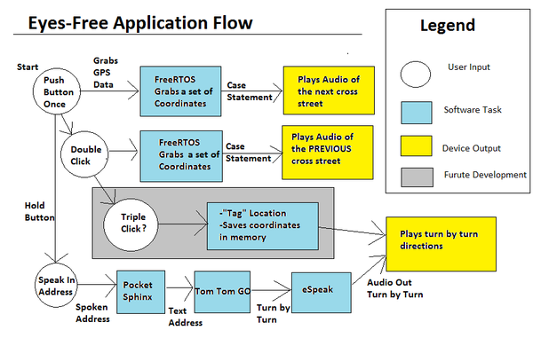
This summer, I will continue working on this project because it is a major stepping stone for my senior project. The idea is the same, but much more open source code will be used which is why I chose to hard code my own map for the CmpE 146 project. Below is the application flow diagram for the Eye's Free GPS:
Laws have been placed to ban cell phone usage while driving a car. Keep in mind, these laws are regarding the actual usage of the mobile phone. Laws have also been placed regarding GPS devices. However, these laws only take care of where the device itself is mounted so the drivers view will not be obstructed. These laws do not protect the driver when he or she is actually looking at the GPS device itself and not the road. It is only a matter of time before looking at and analyzing a moving, real-time map is outlawed while driving a vehicle.
Most "safe" drivers who use GPS, have their passenger read them the turn by turn directions anyway. This is precisely what my finished project will do (without a passenger). My project will also enable people who are visually impaired or people who wont take the time to learn how to use modern devices(non-technical savvy people) to enjoy the benefits of a GPS Navigational System.
References
Acknowledgement
Preet and Bryan [CmpE 146 Lab TAs]
References Used
Links to datasheets are found in the Hardware Design Section
Appendix
Zipped Up Project File:
