F22: Bob Burgers

Contents
Project Title
SOCCER PONG
Abstract
At the time this project was created (fall 2022), the soccer world cup was taking place. Having caught a little of the world cup fever, Soccer Pong looks to combine the gameplay from soccer and the original Pong. Two games from different mediums but with great symmetry. Two players will face each trying to avoid being scored on. A ball will bounce from any surface that is not in the penalty area. Once a player has read the set maximum number of goals, a victor will be crowned. Press the reset button and let’s go again!!! Soccer Pong brings a new flavor to a historic game, taking you into the world of soccer.
Objectives & Introduction
The main objecive of this game was to create a simple pong game and then change it to something more unique. The following were the objectives we had to reach our goal.
- Create a Matrix Driver to display all of the visuals of the game.
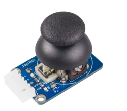
- Implement ADC joysticks controllers Driver to handle the players blocks movement
- Implement Reset and Pause buttons using semaphores interrupts to reset the game and pause the ball movement
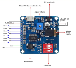
- Incorporate music and special effects by adding a mp3 modules with UART interface.
- Design a PCB that will combine all of the peripherals dfevics with the sj2 board and matrix.
- Create a task that will refresh the matrix driver buffer with the ball and player movement.
- Develop control system with the ability to modify speed and size of blocks
- Create task that will handle ball movement, placement, and hit detection.
- Incorporate the music and sound effects after specific time based events (hitting block, goal, etc).
- Integrate the pause and reset buttons
Team Members & Responsibilities
William Hernandez

Responsibilities
- Led Matrix Graphics
- Gameplay Logic
- Music System Integration
- Game Objects and Hit Detection
- Debugging and Testing
Tin Nguyen
- File:Put picture file here
- PCB
- Music Development
Matthew Hanna

Responsibilities
- Joystick input with ADC reading potentiometer positions for paddle movement
- GPIO input for button pressing pause and reset
- locking mechanism for game pausing and game reset loop entrance
- enclosure fabrication
Schedule
| Week# | Start Date | End Date | Task | Status |
|---|---|---|---|---|
| 1 |
|
|
|
|
| 2 |
|
|
|
|
| 3 |
|
|
|
|
| 4 |
|
|
|
|
| 5 |
|
|
|
|
| 6 |
|
|
|
|
| 7 |
|
|
|
|
| 8 |
|
|
|
|
| 9 |
|
|
|
|
| 10 |
|
|
|
|
General Parts
| Item # | Part | Seller | Quantity | Total Cost |
|---|---|---|---|---|
| 1 | 64x64 RGB LED Matrix | Sparkfun | 1 | $85.95 |
| 2 | SJ-2 Boards | SJSU | 1 | $50.00 |
| 4 | PEMENOL Voice Playback Module | Amazon | 1 | $10.19 |
| 5 | Joysticks | Amazon | 2 | $20.00 |
| 6 | 5v Power Supply | Amazon | 1 | $15.19 |
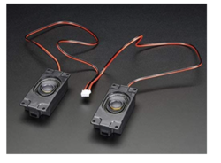
| 7 | Enclosed Speaker Set - 3W 4 Ohm | Amazon | 1 | $12.48 |
| 8 | Buttons | Amazon | 2 | $8.95 |
| 9 | Standoffs | Amazon | 1 | $24.95 |
| 10 | PCB | [link Seller] | 1 | $40.00 |
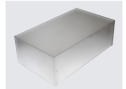
| 11 | Aluminum Enclosure | Anchor Electronics | 1 | $45.12 |
Design & Implementation
Pin Configuration
-
Pin# LED Matrix Pin SJ-2 PIN R1 High Red Led Data P0_6 G1 High Green Led Data P0_7 B1 High Blue Led Data P0_8 R2 Low Red Led Data P0_26 G2 Low Green Led Data P0_9 B2 Low Blue Led Data P1_31 A Mux row select A P1_20 B Mux row select B P1_23 C Mux row select C P1_28 D Mux row select D P1_29 E Mux row select E P2_4 OE Output Enable P2_2 LAT Data Latch P2_1 CLK Clock Signal P2_0 MP3 Module RX UART Receive P4_28 TX UART Transmitter P4_29 Buttons Either Pin Pause Button P2_5 Either Pin Reset Button P2_6 Joysticks X Player 1 P1_30 X Player 2 P0_25 -
Hardware Design
Block Diagram
The full system runs on 5 volts power supply. It powers the SJ2 board and Led Matrix. On The block diagram, the red lines represent the vcc and the black lines represent the ground. The blue lines represent the outputs from peripherals to SJ2 inputs. In the current code, the joysticks and buttons are powered from the SJ2 3v3 vcc pin, however, the PCB powers everything with 5 volts and provides a common ground. The code was left as is, because we did not have enough time to thoroughly test the PCB but the block diagram provides a view of how everything will be connected.
The Joysticks work like potentiometers and supply an ADC signal to the SJ2 board. The joysticks were connected to ADC channels 2 and 4. The mp3 module used UART protocol and were connected to UART 3. The top of the board UART3 pins were used because of their output leds for debugging purposes. The speakers input and ground come from the mp3 module. Both buttons used gpio to connect to the SJ2 board and the other pin were connected to VCC.
Hardware Interface
In this section, you can describe how your hardware communicates, such as which BUSes used. You can discuss your driver implementation here, such that the Software Design section is isolated to talk about high level workings rather than inner working of your project.
Software Design
Show your software design. For example, if you are designing an MP3 Player, show the tasks that you are using, and what they are doing at a high level. Do not show the details of the code. For example, do not show exact code, but you may show psuedocode and fragments of code. Keep in mind that you are showing DESIGN of your software, not the inner workings of it.
Led Matrix
Hardware Implementation and Design
All the pins were set up to be close to each other for better readability. The led matrix required 16 pins as specified above with two being ground. It required 5v with at least 2.1A current. The led matrix uses daisy chaing shift registers to set up the rows. The RGB1 pins set up the color of the top half leds and the RGB2 pins set up the color of the lower half leds. To control the lower half leds both RGB1 and RGB2 need to be set simultaneously. The matrix is 64x64, but works more like a 32x64 matrix. Pins A through E will select the row of the top half. For example, pixel 32x1, will light up when pixel 1x1 is on. This means that both RGB1 and RGB2 need to be set or reset simultaneously. For one pixel to be set, all other pixels need to be reset.
Software Implementation and Design
The led driver drawboard function below was set to draw anything that was set up in the led matrix buffer. By just modifying the buffer every time something changes, the display run smothers and faster. To set up a pixel requires to set up 2 whole lines. First, we tried to have every pixel be set whenever something changes. This lead to a lot of lag and flickering. Since the delay was being call every time one pixel was change. Instead the drawboard function display the buffer, while the refresh buffer function updates the function with any changes done in main.
void led_driver__drawBoard(void) {
 int row, col;
 for (row = 0; row < 32; row++) {
   for (col = 0; col < 64; col++) {
     led_driver__colors_RGB1(led_matrix_refresh_array[row][col]);
     led_driver__colors_RGB2(led_matrix_refresh_array[row + 32][col]);
     led_driver__clock_toggle();
   }
   gpio__set(pins.LAT);
   gpio__set(pins.OE);
   led_driver__drawRow(row);
   gpio__reset(pins.LAT);
   gpio__reset(pins.OE);
 }
 led_driver__insync_row();
}
A background driver was created to introduced full objects to the game. Instead of updating every pixel at a time to create a ball or block, the background driver takes in different size arrays and adds them to the game. There are multiple functions for different game objects but they work the same. Using the fill_word function, all they require is the axis of the pins and the size of the arrays. This made it easier to code the movement of the objects by just following the first pixel of the object in the display. This made it possible to display full 64x64 displays at the same speed as changing one pixel. An important aspect that this function does as well, is to set the color. All the arrays could be set to one color, and the fill word function will changed them to the desired color. This was great for setting score and players objects to look different without adding more arrays to the driver.
static void fill_word(uint8_t y, uint8_t x, uint8_t array_x, uint8_t array_y, uint8_t insert_word[array_y][array_x],
                     color_code color) {
 for (int row = 0; row < array_y; row++) {
   for (int col = 0; col < array_x; col++) {
     if (insert_word[row][col] == 1) {
       led_driver__setPixel(row + y, col + x, color);
     } else {
       led_driver__setPixel(row + y, col + x, insert_word[row][col]);
     }
   }
 }
}
Finally, the led task is runs all of this functions to set up the display. The psuedocode below demonstrate the events the task goes through.Pseudocode initiate the values of top and bottom edge start while loop if the game just started set up the starting screen and wait for a button to be press to start the game fill up the buffer with the original background set up the movement of the joysticks and added them to the buffer delay display what currently is in the buffer
GamePlay Implementation
The gameplay follows a simple pattern as seen in the gameplay flowchart. There is a state machine that determines the states of the ball. This could be where its going or to restart its position after a goal or out of bounce.
The gameplay methodology follows:
- After the game starts, the ball we be placed in the middle of field at location 32x32.
- There is an if statement that waits for both players to move for the ball to start moving. The direction it move is set to any of the for direction states(up-left, upright, down-left ,down-right).
- The ball will then freely move until it reacts to something. The first pixel of the ball is used to detect where it is at all time. The walls and block have hit boxes that take into account where the ball is.
- If the ball detects that its in a compromise location, it will ask it self what did it hit. If the balls detects no collision but its out of the play area, it will be return to the center.
- If it hit a wall, the state machine will use it previous state direction and return it the opposite way. For, example if it can up-right, it will return it up-left.
- If it hit a block, the state machine will use it previous state direction and the position where ball hit the block to return the ball. If the ball hits an edge it will return the ball back where it came from. If the ball hit the opposite edge, the state machine will return the ball, the same it would for if it hit the wall.
- If it hit the area inside the penalty area, then that will signal a goal. The ball will be place back in the center and it will increment the scoring board. The player goal count will be incremented according to whoever scored.
- After a goal is score, the score task will check if the maximum numbers of goals was reach. Depending on who reach the maximum number of goals first a celebration song and display will be activated.
- The Celebration screen will remain and the game will be over, unless the reset button is hit. The reset button will reset all global variables and the game will restart.
Testing & Technical Challenges
Technical Challenges
Our main challenges hardware wise came from loose connections. If we were to do the project again from scratch, the first priority would be to create and assemble the pcb. Having everything set up would save us a lot of time debugging hardware thinking that some of the matrix issues were software related.
Additionally, some of the movements are rigids, with the values changing at a constant rate instead of slowing increasing or decreasing. We would have like to assigning someone to work on specific delays and modifications to make the movement more dynamic.
Testing
Since we only had one Led Matrix, we would first test are assigned peripherals using individual Leds or by using printfs. Then we would meet and integrated those components and tested them individually with the Led Matrix.
This game required a lot of geometry because of the freedom of movement of the ball. A lot, of testing was done to find all of the angles where the ball will disappear or hit the incorrect angles. The ball sometime was set to stop as soon as it left a playable area to find the correct wholes in the play area.
The joysticks were manipulated to find the correct speed for playability. Sometimes, we would just change the values and only move the blocks to find the correct speed.
Similarly, multiple different games tested the correct speed of the ball. If it was too fast it provided a clear resolution of the ball but hard to play. While, if it was too slow, the refresh rate will make the ball translucent. All, we could do is keep playing the game, until we reach a good medium.
<Bug/issue name>
- Joystick input had a fixed paddle speed
- Pause and Reset buttons service with ISR was difficult to debounce, moving button input detection to a Task would be more practical
- If a ball hit the edges of the play area, they will fly out of bounce. Everything outside the main area was to put the ball back in the middle.
- Strangely, we had a lot of flickering and thought it was a software bug but it was a hardware issue. Not all power adaptors work, even if they had the same voltage and current values.
- The music would stop playing or ending earlier. The mp3 module was set to gpio first and then change to UART. The datasheet did not provide all necessary codes for the correct use of the commands. Research was done to find that an extra command was needed for all commands that require the mp3 module to jump between songs.
- FPS issues with the ball looking like it was hitting one area but it was delay. The leds lights don't light up as always expected, therefore accommodations were done, where if the ball is around the area and its close enough it will count as a hit or goal.
- The PCB rows were backwards. The pcb was created to hold the sj2 board, however, the row were backwards and needed to be remade. A second board was made and bought, but it got delayed and lost in Los Angeles, by the time it arrived, we did not want to mess with the system. We did not have enough time to integrate the pcb into the game but were able to logically tested using another sj2 board. Checking if the connections match.
Conclusion
We are quite satisfied with the project. We would had like to add more dynamism to the gameplay but had to deal with unfortunates situations which negated some of the time we had set for improving the gameplay. As simple as the game might seem, making it two player game added longevity to the play time. For some of us, this was our first semester as a master student. It was a pretty tough introduction to embedded systems, but a fun introduction as well. We got to work more with peripherals that we had not used before. Learning about FreeRtos, UART, SPI, and I2C made us feel more prepare for future jobs. Working as a team for this project thought as a lot as well. It thought how important communication is for a project fluidity. Overall, the project provided and tested us on new knowledge, thought us new skills that we believe will be essential for our future career in embedded systems.
Project Video
Project Source Code
References
Acknowledgement
We would like to thank Preet for providing and teaching a course that gives a more unique hands on approach to teaching. To be able to learn and perform lab/projects that are more relevant to what currently being used in industry, gives a since of optimism for what we will face in the near future.
Appendix
You can list the references you used.


