F21: FollowMe
Contents
Abstract
FollowMe is a video game where you follow the correct directions. The LED matrix will display a series of arrows and the player or players need to correctly wave their hand over their gesture sensor to earn points. However, watch out for the background color of the arrow. If the background is green, then the players need to wave their hand in that direction; i.e, an arrow pointing left with a green background means wave your hand from the right to the left (wave left). If the background is red, then the players need to wave their hand in the opposite direction; i.e, an arrow pointing up with a red background means wave your hand from the top to the bottom (wave down).
There'll be two modes:
1. Timed mode: each player tries to get the most correct waves until the time runs out. The rate at which the arrows change will increase as the timer counts down.
2. Endurance mode: each player tries to stay alive the longest. One wrong wave then you're eliminated, the last player standing wins.
At the end, the LED matrix will display the leaderboard for the players and how many waves/instructions they got correct.
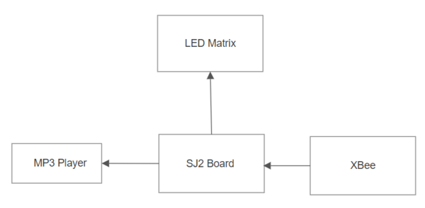
- Block Diagram of Follow Me needs to be added
Objectives & Introduction
Project Introduction
1.Analyse hand waving/movement using a gesture sensor
2.Connect different microcontrollers wirelessly to exchange information
3.Read a file from SD card on the microcontroller and get the MP3 data using MP3 decoder
4.Display different screens according to the game level(Title screen, Arrows and leaderboards)
Project Objectives
1. Gestor Control: APDS-9960 gesture sensor on SJ2 board should respond to hand waving. I2C interface will be used for this sensor.
2. ZIGBEE wireless: UART interface used to connect the wireless devices, which will send information to other boards.
3. MP3 decoder: MP3 data will be fetched from mini SD card reader using SPI interface.
4. 64x64 RGB LED matrix: LED will be controlled by GPIO of SJ2 board. The LED will display game graphics.
5. 3D Printed enclosure: The system will be enclosed in a 3D printed enclosure.
Team Objectives
1.Learn and understand the APIs of the Real Time Operating System
2.Use different embedded protocol to interface the system
3.Learn to design a module and interface the modules by reading datasheets
4.Integration and testing to deliver the final product
5.Track and respond to the reported bug and document the bugs and solutions.
Team Members & Technical Responsibilities
- Jonathan Doctolero
- Gesture Sensor Driver
- Gameplay Development
- Enclosure Design
- Priyanka Rai
- RGB Matrix Driver
- Gameplay Development
- Ravi Kiran Dendukuri
- XBEE functionality
- Gameplay Develoopment
- PCB Design
- Yashwanth Kumar Nelakuditi
- MP3 Decoder Design
- Gameplay Development
- Wiki Update
Schedule
| Week# | Start Date | End Date | Task | Status | Deliverable |
|---|---|---|---|---|---|
| 1 |
|
|
|
|
|
| 2 |
|
|
|
|
|
| 3 |
|
|
|
|
|
| 4 |
|
|
|
|
|
| 5 |
|
|
|
|
|
| 6 |
|
|
|
|
|
| 7 |
|
|
|
|
|
| 8 |
|
|
|
|
|
| 9 |
|
|
|
|
|
| 10 |
|
|
|
||
| 11 |
|
|
|
Bill of Materials (General Parts)
| PART NAME |
PART MODEL & SOURCE |
QUANTITY |
COST PER UNIT (USD) |
|---|---|---|---|
|
|
|
|
|
|
| |
|
|
| |
|
|
|
|
|
|
|
|
|
|
|
|
|
|
| |
|
|
|
|
Design & Implementation
PCB Design
We chose EasyEDA for PCB design,it is an online free software.
Schematic Design:
Our project is divided into two main circuits, first is main and master controller circuit and second is a slave controller circuit.
Master Controller PCB schematic:
This circuit will do the wire interfacing of SJTwo board to xbee, mp3 decoder, led matrix. This is the master board and it will recieve values from all the controllers and peripherals
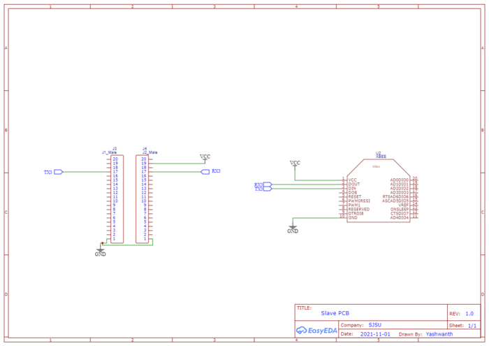
Slave Controller PCB schematic:
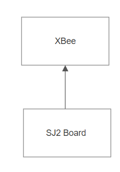
This circuit will do the wire interfacing of SJTwo board to xbee which will send the values of Gesture to the master Xbee.
PCB Layout:
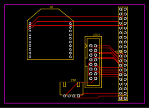
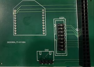
With EasyEDa we can conver schematic to PCB it auto routes itself.
Hardware Interface
Hardware Interface gives an overview of the entire system which consists of the two SJ2 controllers, one board is used as Main/Master controller and other as Slave controller.
- The Slave controller uses the onboard Gesture on SJ2 which is interfaced via UART protocol.
- The Main controller board is used to control LED Matrix.This matrix displays the Arrows and accordingly player should play and value received from the slave through Wireless Module is used to determine whether it is right or wrong.
Hardware Components Implementation
LED Matrix
A 64 x 64 RGB LED Matrix will be powered up through a 5V/4A DC adapter and is interfaced with the board to play the game FOLLOW ME with the background music. The matrix has 2 planes (upper and lower), both of which will be programmed separately. Planes are made by dividing 64 rows into 2 halves, i.e. first 32 rows in plane 1 and the remaining 32 rows in plane 2. Five signals (viz. A, B, C, D, and E) which are connected to 5 GPIOs of the SJ-2 board are used to select rows from each plane. R1, G1, B1 signals with 64-bit registers are used to address individual led from the selected row in plane 1. Similarly, R2, G2, B2 signals used to address individual led from the selected row in plane 2.
A single clock is interfaced to these 6 64bit shift registers. Hence, at one clock signal, we fill and enable a column corresponding to two selected rows. Once the clocking and register shifting is done, the data need to be latched to the register which in turn enables the corresponding LED. Then the LATCH is set to mark end of the row and reset to move to next row. The output enable signal is enabled to push the data to the selected row. The output enable signal is disabled again to select the other row. All of these steps are repeated at very less time intervals so that the human eye perceives it as one complete frame (Persistence of Vision).
Pin Configuration
| Pin | Pin Description |
|---|---|
| R1 | Sets upper panel's Red data |
| G1 | Sets upper panel's Green data |
| B1 | Sets upper panel's Blue data |
| R2 | Sets lower panel's Red data |
| G2 | Sets lower panel's Green data |
| B2 | Sets lower panel's Blue data |
| A | Sets row bit 0 |
| B | Sets row bit 1 |
| C | Sets row bit 2 |
| D | Sets row bit 3 |
| E | Sets row bit 4 |
| nOE | Set to switch the LEDs off when transitioning from one row to the next |
| LATCH | Set to mark completion of one row |
| CLK | Set to access each pixel |
| GND | Ground pins to be connected with board's GND. |
Software Design
1. Timer - Mode
a) Set the timer to finish the game in given time
b)
2. Endurance -Mode
a) Play until Far gesture is detected
b)
Game rules:
a) Game comprises of 3 levels (level 2 on reaching score 15 and level 3 on reaching score 30).
b) Primary objective is to move hands in direction of arrow if the color is GREEN and in opposite direction if the color is RED.
c) Score increases by 1 point for right hand movement.
d) Level 3 is faster so make sure you tune your reflexes up.
e) Reach score 50 to win the game.
There are 2 tasks involved to ensure functioning of the game.
a) Task 1:
- Display the game's title screen. The game begins with receiving gesture from any of the player.
- Also used to display game over screen / win screen.
b) Task 2:
- Enter into game mode to play the game.
- Generate arrow matrix frame for random direction(horizontal, vertical, up and down) and random color(Red/Green).
- Detect the player's gesture from his board, compare it with arrow's location and color.
- Display score and level.
- Upon receiving Far gesture from the player, stop game and return to title screen or to restart the game once it is over.
Implementation
Testing & Technical Challenges
RGB LED Matrix
1. RGB LED Matrix
- The ordered matrix was faulty, needed to order another one, project start got delayed a bit due to this.
- Getting control of the matrix was challenging as it needs to follow specific sequence of pin enabling/disabling at appropriate timing.
- Setting right delays to avoid flickers and get smooth transitioning between frames by using delays or for loops.
- Designing elements of the game (title screen and arrow objects) which required careful plotting of pixel data.
Conclusion
Conclude your project here. You can recap your testing and problems. You should address the "so what" part here to indicate what you ultimately learnt from this project. How has this project increased your knowledge?
Project Video
Upload a video of your project and post the link here.
Project Source Code
References
Acknowledgement
Any acknowledgment that you may wish to provide can be included here.
References Used
RGB LED Matrix Interfacing and Designing
- Datasheet and Hookup guide
- Wiring and pin information
- Hex code generator to build the led matrix [3]
MP3 Decoder
Gesture & Orientation Sensors
General/Miscellaneous
Appendix
You can list the references you used.

