Difference between revisions of "F19: Tower Defense in Space"
Proj user10 (talk | contribs) |
Proj user10 (talk | contribs) (→Source Code) |
||
| Line 508: | Line 508: | ||
=== <font color="000000"> Source Code </font> === | === <font color="000000"> Source Code </font> === | ||
| − | |||
| − | |||
=== Advice for Future Students === | === Advice for Future Students === | ||
Revision as of 16:15, 17 December 2019
Contents
Grading Criteria
- How well is Software & Hardware Design described?
- How well can this report be used to reproduce this project?
- Code Quality
- Overall Report Quality:
- Software Block Diagrams
- Hardware Block Diagrams
- Schematic Quality
- Quality of technical challenges and solutions adopted.
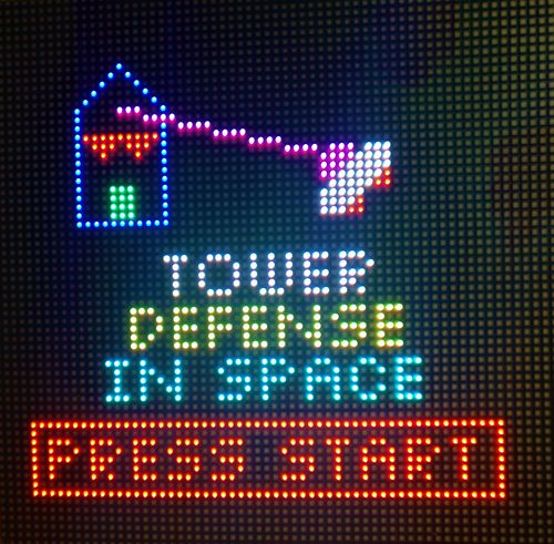
Tower Defense...In Space!
Tower Defense ... In Space.
Abstract
My abstract goes here.
Introduction and Objectives
intro here please.
Team Members
|
TEAM MEMBERS & RESPONSIBILITIES | ||||
|---|---|---|---|---|
|
Team Members |
Administrative Roles |
Technical Roles | ||
|
Team Lead |
| ||
|
Git Repo Manager |
| |||
|
Wiki Report Manager |
| ||
|
Bill of Materials Manager |
| ||
Schedule
|
TEAM MEETING DATES & DELIVERABLES | ||||
|---|---|---|---|---|
|
Week# |
Date Assigned |
Deliverables |
Status | |
| 1 | 10/15/19 |
|
| |
| 2 | 10/22/19 |
|
| |
| 3 | 10/29/19 |
|
| |
| 4 | 11/5/19 |
Kelvin
|
| |
| 5 | 11/12/19 |
Kelvin
Polin
Ryan
Zach
|
| |
| 6 | 11/19/19 |
Kelvin
Polin
Ryan
Zach
|
| |
| 7 | 11/26/19 |
Kelvin
Polin
Ryan
Zach
|
| |
| 8 | 12/3/19 |
|
| |
| 9 | 12/10/19 |
|
| |
Bill of Materials
|
Top Level | ||||
|---|---|---|---|---|
|
PART NAME |
PART MODEL & SOURCE |
QUANTITY |
COST PER UNIT (USD) | |
| |
|
|
| |
| |
|
|
| |
| |
|
|
| |
| 64x64 RGB LED Matrix* | Adafruit | 1 | $104.07 | |
| 5V 4A PSU | - | 1 | FREE | |
|
Breakout Board PCB** | ||||
|---|---|---|---|---|
|
Item # |
PART NAME |
PART SOURCE |
QUANTITY |
COST PER UNIT (USD) |
| 1 | IC REG LINEAR LD1117S33CTR | DIGIKEY | 5 | $0.351 |
| 2 | MHS16N-ND 16POS CONN 2.54MM | DIGIKEY | 2 | $2.60 |
| 3 | CAP CER 0.1UF 25V X7R 1206 | DIGIKEY | 5 | $0.221 |
| 4 | CAP CER 10UF 16V X5R 1206 | DIGIKEY | 5 | $0.202 |
| 5 | RES SMD 470 OHM 1% 1/4W 1206 | DIGIKEY | 10 | $0.0267 |
| 6 | PTC RESET FUSE 24V 500MA 1206 | DIGIKEY | 10 | $0.1588 |
| 7 | CONN SOCKET 40POS 0.1 TIN PCB | DIGIKEY | 2 | $5.03 |
| 8 | Manufacturing x 5 boards * | JLCPCB | 1 | $29.81 |
|
Gamepad PCB** | ||||
|---|---|---|---|---|
|
Item # |
PART NAME |
PART SOURCE |
QUANTITY |
COST PER UNIT (USD) |
| 1 | Analog 2-axis Thumb Joystick w/ select button | Amazon | 1 | $7.67 |
| 2 | SAM8205-ND 10POS 1.27MM | DIGIKEY | 5 | $3.38 |
| 3 | LED GREEN 1206 SMD | DIGIKEY | 5 | $0.24 |
| 4 | LED RED 1206 SMD | DIGIKEY | 5 | $0.257 |
| 5 | RES 1K OHM 1% 1/2W 1206 SMD | DIGIKEY | 5 | 0.0358 |
| 6 | CAP CER 0.1UF 50V X7R 1206 | DIGIKEY | 5 | $0.088 |
| 7 | 12x12x7.3mm Tactile Push Button w/ cap (pack of 25) | Amazon | 1 | $7.89 |
| 8 | Manufacturing x 5 boards * | JLCPCB | 1 | $14.21 |
* Shipping and tax included in value shown in the cost per unit column
** Only parts that were purchased are displayed.
System Design
System Block Diagram
Hardware Design
Overview
At a high level hardware integration requirements fell into two categories:
1. Reduce risk of unreliable cable connections and eliminate possibility of damage to components through unexpected disconnections, power surges, etc.
2. Provide a more fluid physical interface for the user to interact with the game via hardware
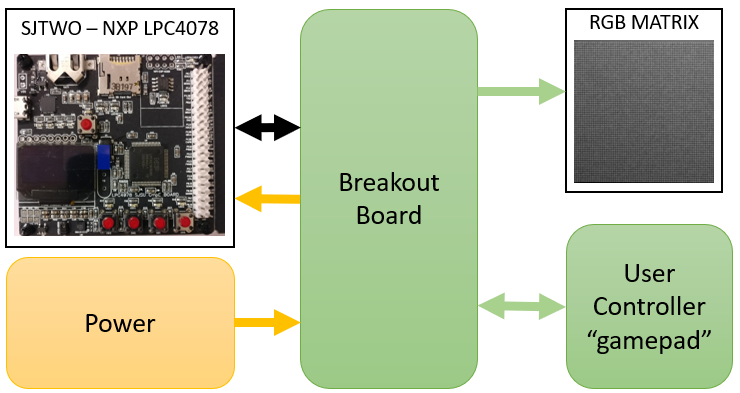
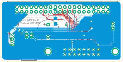
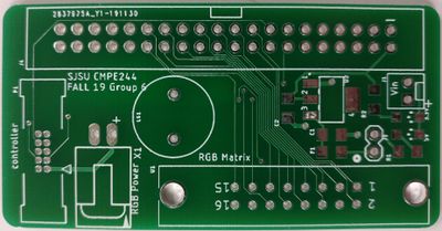
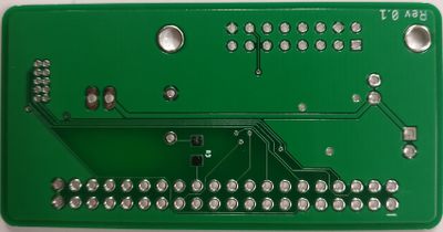
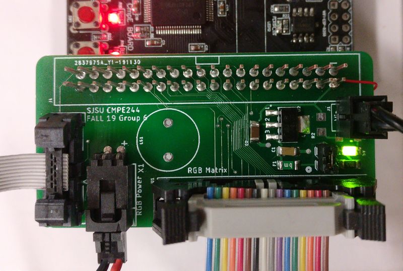
To accomplish these goals, two boards were designed: a breakout board and a gamepad controller. The breakout board serves as a connection hub between all system hardware components; power, the RGB matrix, the SJTWO board, etc. while the joystick provides a cleaner package to present the user with the games inputs. The diagram below shows the relationship between the main subsystems:
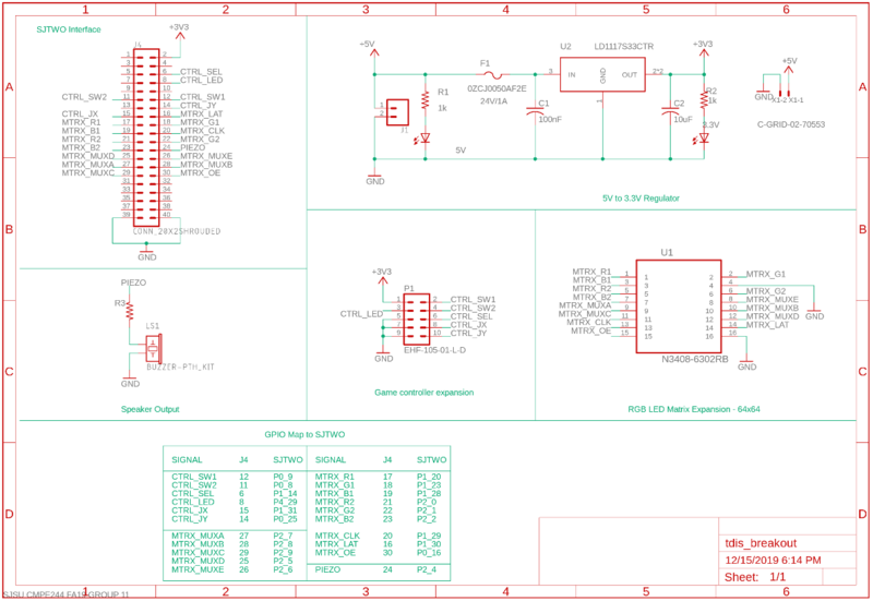
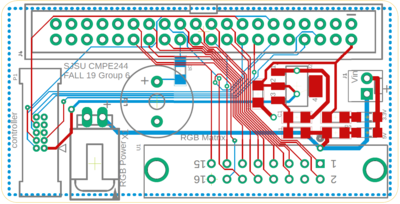
All board designs were done using EAGLE and manufactured by JLCPCB. Both boards were only two layers and used passive components for the most part.
Breakout Board Design
The breakout board design requirement was to interface all external hardware components with the embedded system (SJTWO). The hardware connections are:
1. The 64x64 RGB Matrix
2. Output power to the RGB Matrix
3. User game controller (see next section)
4. Input power supply (5V)
5. The SJTWO embedded system
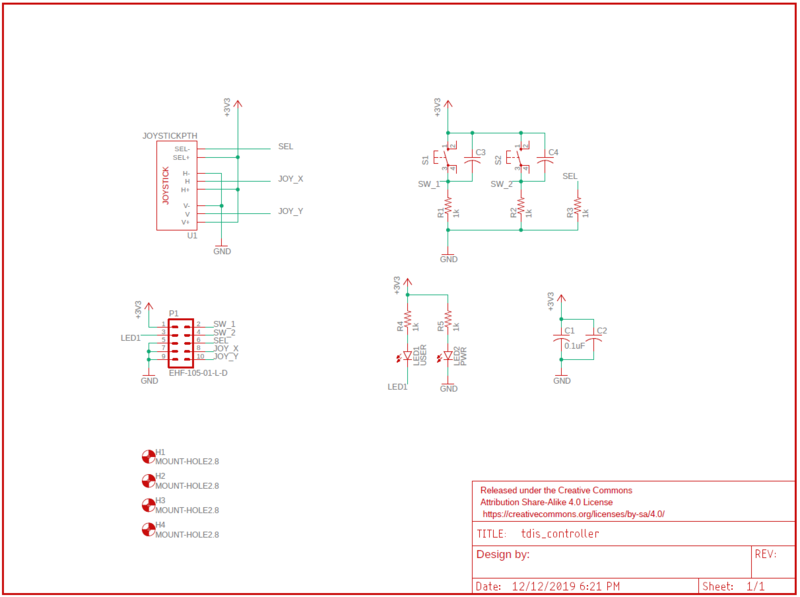
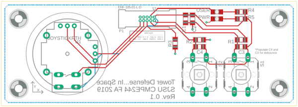
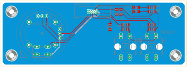
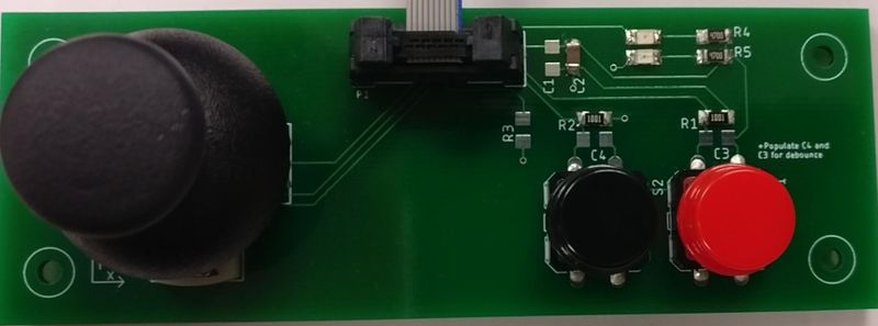
Gamepad Hardware Design
The gamepad board design requirement was to provide a more packaged interface for the user to interact with the game.
Hardware Integration
(rgb matrix driver, stuff like that)
Software Design
System Flow Charts
System Testing and Validation
Technical Challenges
Conclusion
Conculsion please.
