F18: baem geim
Contents
Grading Criteria
- How well is Software & Hardware Design described?
- How well can this report be used to reproduce this project?
- Code Quality
- Overall Report Quality:
- Software Block Diagrams
- Hardware Block Diagrams
- Schematic Quality
- Quality of technical challenges and solutions adopted.
Project Title
baem geim - Snake Game Reborn
Abstract
baem geim is a revived, most amusing Snake Game where a player maneuvers a line which grows in length, with the line itself and wall as obstacle. The concept originated in the 1976 arcade game Blockade, and the ease of implementing snake has led to hundreds of versions for many platforms. This is a new version of snake game which we have developed. The player controls the dot using handheld joystick. As it moves forward, it leaves a trail behind, resembling a moving snake. The snake movement is visually displayed in real time on a 32*32 LED Matrix. The player attempts to eat randomly generated dots as fruits by running into it with the head of the snake. Each fruit eaten increases the length of the snake and controlling it becomes progressively difficult. The player loses the game if the snake runs into itself or hits the screen border. The game is designed using two SJone LPC1758 microcontroller boards one each to drive LED Matrix and Joystick module respectively. They communicate wirelessly through RF Nordic transceiver.
Objectives & Introduction
The main objective of the project is to develop a 2D soleplayer snake game. Other milestones to achieve the objective are as below.
- Visually display the movement of the snake on LED Matrix in real time.
- Control the movement of the Snake through Joystick.
- Transmit the control data wirelessly from input to output console through Nordic transceiver.
- Design PCB for distribution of input power appropriately between two SJone boards.
The project is broadly divided into two modules.
1. Input Module: The input module connects SJone board to two-axis joystick which is used to control the snake advancement. Nordic transmitter continuously transmits control packets to the output module.
2. Output Module: The output module connects another SJone board to LED Matrix for visual display. It recursively polls to receive control packets from the input module and updates the snake movement as per user's input.
Team Members & Responsibilities
- Bharath Vyas Balasubramanyam
- Driver for Nordic Wireless Transceiver and Joystick
- Neeraj Dhavale
- Driver for LED Matrix and Nordic Wireless Transceiver
- Sudarshan Aithal
- Design of Game Algorithm
- Vignesh Kumar Venkateshwar
- Wiki Management, PCB Design and Driver for Joystick
Schedule
| Week# | Date | Task | Status | Actual Completion Date | |
|---|---|---|---|---|---|
| 1 | 09/22/2018 |
|
|
| |
| 2 | 09/29/2018 |
|
|
| |
| 3 | 10/06/2018 |
|
|
| |
| 4 | 10/13/2018 |
|
|
|
|
| 5 | 10/20/2018 |
|
|
|
|
| 6 | 10/27/2018 |
|
|
|
|
| 7 | 11/03/2018 |
|
|
|
|
| 8 | 11/10/2018 |
|
|
|
|
| 8 | 11/13/2018 |
|
|
|
|
| 9 | 11/17/18 |
|
|
|
|
| 9 | 11/20/18 |
|
|
|
|
| 9 | 11/22/18 |
|
|
|
|
| 9 | 11/22/18 |
|
|
|
|
| 10 | 11/24/18 |
|
|
|
|
| 10 | 11/27/18 |
|
|
|
|
| 11 | 12/01/18 |
|
|
|
Parts List & Cost
| Item# | Part Description | Vendor | Qty | Cost |
|---|---|---|---|---|
| 1 | SJOne LPC1758 Microcontroller Board | Preet | 2 | $160.00 |
| 2 | 32x32 RGB LED Matrix | Amazon | 1 | $56.00 |
| 3 | 5V/4A Power Adapter | Amazon | 1 | $8.99 |
| 4 | DC Barrel Jack Adapter - Female | Fry's Electronics | 1 | $2.90 |
| 5 | Osepp Joystick Module | Fry's Electronics | 1 | $6.54 |
| 6 | Right Angle Mini Quad Band Antenna | Amazon | 2 | $16.52 |
| 7 | PCB | JLC PCB | 5 | $19.36 |
| Total | - | - | $270.31 |
Design & Implementation
Hardware Design
The Hardware design for baem geim involves the use of two SJone LPC1758 microcontroller boards, 32x32 RGB LED Matrix, Joystick module and Nordic Wireless Transceiver as described below. Pin configuration information for integration with PCB and power source have been detailed.
LED Matrix
The Project uses 32x32 6mm pitch RGB LED Matrix consisting of 1024 RGB LEDs.
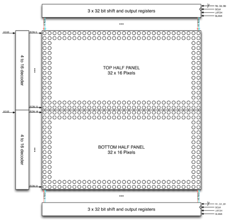
32 rows of LED matrix have been divided into 16 interleaved sections/strips. The first section is the 1st 'row' and 16th 'row' (32 x 2 RGB LEDs = 64 RGB LEDs) the second section is 2nd 'row' and 17th 'row' and so on.
On the PCB is 12 LED driver chips. These are like 74HC595s but they have 16 outputs and they are constant current. 16 outputs * 12 chips = 192 LEDs that can be controlled at once, and 64 * 3 (R G and B) = 192. So now the design comes together. We can have 192 outputs that can control one line at a time, with each of 192 R, G and B LEDs either on or off. The LPC1758 controller selects which section to currently draw (using A, B, C and D address pins - 4 bits can have 16 values). Once the address is set, the controller clocks out 192 bits of data (24 bytes) and latches it. Then it increments the address and clocks out another 192 bits, etc until it gets to address #15, then it sets the address back to #0.
To light up an individual pixel, appropriate row value is loaded on to the address pins A,B,C & D, Clock is set out to traverse the row
and when required pixel is reached, the latch is set high to turn ON the LED.
Technical Specification:
Dimensions: 190.5mm x 190.5mm x 14mm / 7.5" x 7.5" x 0.55"
Panel weight with IDC cables and power cable: 357.51g
5V regulated power input, 4A max (all LEDs on)
5V data logic level input
2000 mcd LEDs on 6mm pitch
1/16 scan rate
Indoor display, 150 degree visibility
Displays are 'chainable'
Joystick:
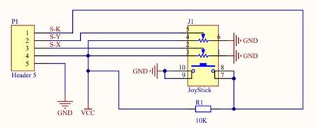
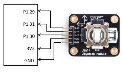
The project uses a 2-axis self centered joystick module from osepp. Its goal is to communicate motion in 2D to SJone board. This is achieved by using two independent 10K potentiometers (one per axis) which can be used as dual adjustable voltage dividers, providing 2-axis analog input in a control stick form. The Joystick stick design consists of Gimbal mechanism along with two potentiometers. When joystick is rotated, it moves a narrow rod, that sits in two rotatable shafts (Gimbal). One of the shafts allows motion in the X-axis(left-right) while the other allows motion in the Y-axis (up-down). Tilting it forward and backward pivots the Y-axis shaft, while tilting it left to right pivots X-axis shaft. Moving it diagonally pivots both shafts.
To read the joystick's physical position, we need to measure the change in resistance of potentiometer connected to each joystick shaft. The change can be read by LPC microcontroller's analog pin using ADC. With the microcontroller's 12-bit resolution, the values on each analog channel(axis) can vary from 0 to 4095. Thus, if the stick is moved on X-axis from one end to the other, the values change from 0 to 4095 and similar thing happens when it's moved along Y-axis. At Joystick's default position, its value is about 2048.
Technical Specification:
Operating voltage output : 3.3V – 5V MAX
Analog input
two 10K potentiometers with common ground per axis
Spring auto return to center on knob
Operating temp range: +32°F to +158°F (0°C to +70°C)
Unit Weight: 4 oz
Nordic Wireless:
The project uses nRF24L01+ single chip 2.4GHZ transceiver rooted on SJone board to establish wireless communication between input and output modules. It uses embedded baseband protocol engine (Enhanced ShockBurst™), suitable for ultra low power wireless applications. The nRF24L01+ is designed for operation in the world wide ISM frequency band at 2.400 - 2.4835GHz. It is configured and operated through Serial Peripheral Interface (SPI0) of LPC1758 microcontroller. The embedded baseband protocol engine (Enhanced ShockBurst™) is based on packet communication and supports various modes from manual operation to advanced autonomous protocol operation. Internal FIFOs ensure a smooth data flow between the radio front end and the system’s MCU. Enhanced Shock-Burst™ reduces system cost by handling all the high speed link layer operations. The radio front end uses GFSK modulation. It consists of 126 different RF channels, which gives a possibility to have a network of 125 independently working modems in one place. It has a power consumption of about 12mA during transmission which is even lower than a single LED. Its operating voltage is between 1.8 and 3.7V.
Hardware Interface
In this section, you can describe how your hardware communicates, such as which BUSes used. You can discuss your driver implementation here, such that the Software Design section is isolated to talk about high level workings rather than inner working of your project.
Software Design
Show your software design. For example, if you are designing an MP3 Player, show the tasks that you are using, and what they are doing at a high level. Do not show the details of the code. For example, do not show exact code, but you may show psuedocode and fragments of code. Keep in mind that you are showing DESIGN of your software, not the inner workings of it.
Implementation
This section includes implementation, but again, not the details, just the high level. For example, you can list the steps it takes to communicate over a sensor, or the steps needed to write a page of memory onto SPI Flash. You can include sub-sections for each of your component implementation.
Testing & Technical Challenges
Describe the challenges of your project. What advise would you give yourself or someone else if your project can be started from scratch again? Make a smooth transition to testing section and described what it took to test your project.
Include subsections that list out a problem and solution, such as:
<Bug/issue name>
Discuss the issue and resolution.
Conclusion
Conclude your project here. You can recap your testing and problems. You should address the "so what" part here to indicate what you ultimately learnt from this project. How has this project increased your knowledge?
Project Video
Upload a video of your project and post the link here.
Project Source Code
References
Acknowledgement
Any acknowledgement that you may wish to provide can be included here.
References Used
List any references used in project.
Appendix
You can list the references you used.


