F18: Catch me if you can
Contents
Grading Criteria
- How well is Software & Hardware Design described?
- How well can this report be used to reproduce this project?
- Code Quality
- Overall Report Quality:
- Software Block Diagrams
- Hardware Block Diagrams
- Schematic Quality
- Quality of technical challenges and solutions adopted.
Project Title
Catch Me If You Can
Abstract
"Catch me if you can" is a fun game where the user must be attentive and agile enough to catch the randomly dropping eggs from above into a basket with increasing difficulty levels for an intriguing experience. This is all displayed in the LED matrix acting as the screen. The system will consist of two SJ1 boards, one used as a game console with which user will try to catch the eggs by moving it in the required orientation. The other board will control the display module that displays the graphics of eggs falling and also the basket movement. The display module shall communicate with the game console via RF Nordic transceiver. There will be game sounds produced by the display module board for various events during the game like entering a new level.
Objectives & Introduction
Objective
To develop an Embedded system in the form of a 2D game involving a Matrix LED display acting as the Human Machine Interface to guide the player along the way while playing the game. This project aims at integrating micro-controller peripheral drivers and the application software in a meaningful way, where the accelerometer data is sent out from a node via wireless Nordic transceiver to control slider movement on the other node to control the game according to player's performance.
Introduction
The Project consists of three main modules:
Control Module: It consists of accelerometer on SJ one board. Calibrated board orientation is sent to the Display Module via Wireless Module.
Display Module: It is responsible for controlling 32*32 LED Matrix and Piezo buzzer interfaced to SJ One Board.
Wireless Module: It is used to establish communication between Display and Control module.
About the game
- Player should collect the eggs into the basket which are shot from the canon.
- Press switch on the console (SJOne board) to start the game.
- Tilt the console left or right to move the basket.
- Collect the eggs.
- Avoid red objects, if caught Game Over, else continue to collect eggs till the end of level.
Team Members & Responsibilities
- Aquib Abduljabbar Mulani
- Wireless chip TX driver/application and calibrating accelerometer.
- Kailash Kumar Chakravarty
- RGB LED 32x32 matrix driver and game application code.
- Nandini Mandya Shankaraiah
- Audio output and Wireless chip RX driver/application.
- Rishabh Sheth
- PCB design.
- Swanand Sapre
- Console and Game design and application code.
Schedule
| Week# | Date | Task | Status | Actual Completion Date |
|---|---|---|---|---|
| 1 | 10/16/2018 |
|
Completed | 10/25/2018 |
| 2 | 10/30/2018 |
|
Completed | 11/05/2018 |
| 3 | 11/06/2018 |
|
Completed | 11/13/2018 |
| 4 | 11/13/2018 |
|
Completed | 11/16/2018 |
| 5 | 11/20/2018 |
|
Completed | 11/22/2018 |
| 6 | 11/27/2018 |
|
Completed | 12/1/2018 |
| 7 | 11/30/2018 |
|
Completed | 12/06/2018 |
| 8 | 12/04/2018 |
|
Completed | 12/11/2018 |
| 9 | 12/11/2018 |
|
Completed | 18/11/2018 |
Parts List & Cost
| Sl No | Parts | Seller | Quantity | Price |
|---|---|---|---|---|
| 1 | SJOne LPC1758 Microcontroller Board | Preetpal Kang | 2 | $160 |
| 2 | RGB LED Matrix Panel - 32x32 | Sparkfun | 1 | $55.6 |
| 3 | Piezo Buzzer | Amazon | 2 | $1.5 |
| 4 | Accelerometer | On board | 1 | NA |
| 5 | Switches | On board | 4 | NA |
| 6 | Portable Power Supply | Local seller | 1 | $5 |
| 7 | RF Nordic | On board | 1 | NA |
| 8 | BOM / PCB components | Moser | - | $20 |
Design & Implementation
Hardware Design
Discuss your hardware design here. Show detailed schematics, and the interface here.
PCB Design
PCB is an important part of the embedded system, it is certainly true for this project as it reduced wire complexity and gave independent power to our circuit. There are many softwares available for PCB design, among them Eagle and KiCAD are more popular and both software are free for students. We chose KiCAD (v5.10.0) for PCB design over Eagle because, it is opensource so we din't have to worry about the license and it offers free usage for students for an year. The second reason was that, all of our team members was new to PCB design so the learning curve was same for both software but we found a good tutorial series for KiCAD on youtube ( KiCAD tutorials ). KiCAD has its own issues which are discussed in the issue section of this wiki.
The steps involved in the PCB design process are as discussed below:
1. Schematic Design
Our project can be divided into two main circuits, first is game display circuit and second is a console circuit. We decided to design separate PCB for both circuits as doing so can make wiring easy and improve the user experience.
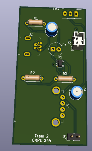
a. Display PCB schematic
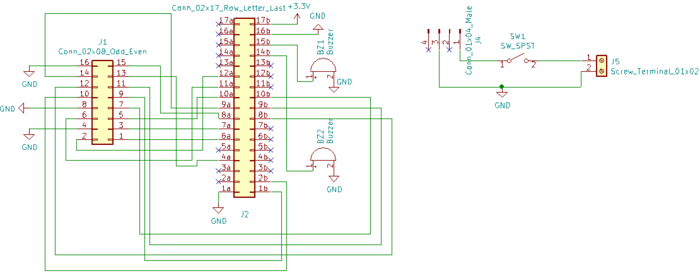
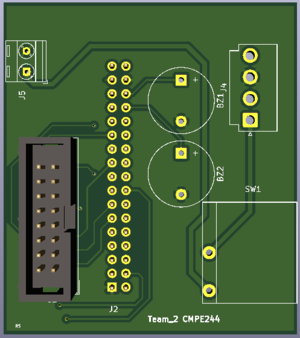
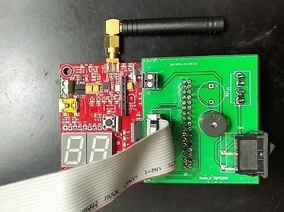
Display PCB has two independent circuits. One circuit is to connect SJOne board to LED panel connector and with two piezo buzzers. While another circuit is to connect one unused power cable of LED panel to SJOne board so that we don't have to power SJOne board from PC while we are playing the game.Our preliminary idea was to make this PCB, a Arduino kind of shield but for SJOne board.
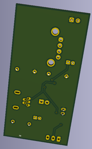
b. Console PCB schematic
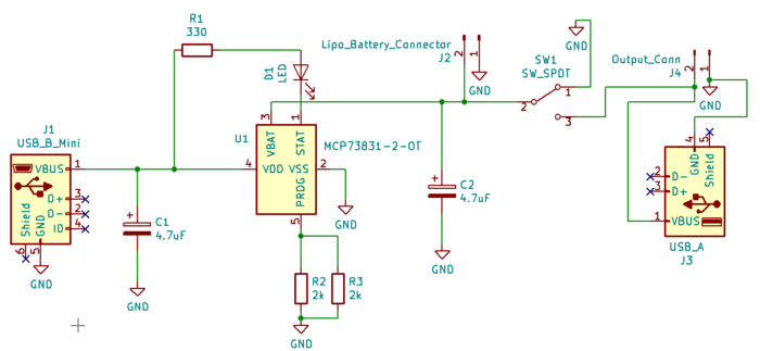
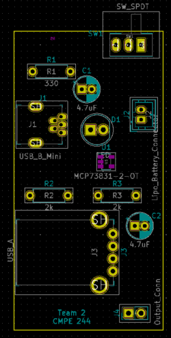
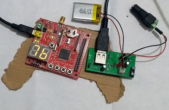
In this game, console is used to move the basket to catch fast falling eggs and if there is any wire attached to console then it is very inconvenient for the user to play so we decided to make PCB which can charge battery and power the console while the user is playing. As shown in figure heart of the circuit is microchip's MCP73831 LiPo battery charging management IC. One LED is connected to it's Status Pin which glows when the battery is charging. A mini USB B port is given to connect one end of USB cable to charge the battery while another end can be connected to PC and any 5V mobile charger. At the time of playing the game, the user has to connect one end of the cable to USB A port this PCB and one end to SJOne Board's mini USB B port. Every time user has to turn on/off switch to use the console on battery power.
2. PCB Layout
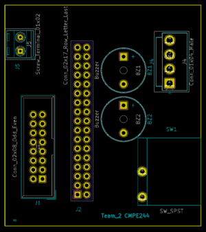
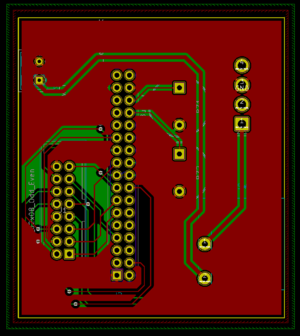
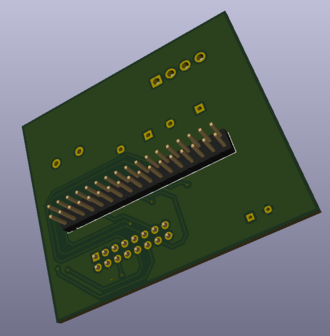
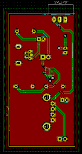
After schematic design, the most important step is to connect the PCB layout. In KiCAD components is not automatically associated with it's PCB footprint so it's user's responsibility to connect right PCB footprint with the right components. In our case, we don't have the footprint of JLC connector and Rocker switch so we first made it in a different window and saved it. The amazing feature of KiCAD is ones we have done with PCB layout we can visualize PCB in 3D by pressing just one button. Below are actual screenshots of both, PCB layout & their 3D model.
a. Display PCB layout
b. Console PCB layout
3. PCB manufacturing and soldering
We chose JLC PCB to manufacture our PCB because it is the cheapest and convenient option available for any prototype PCB manufacturing. It just cost us $2 for 10 quantity PCB and $17 for shipment. We receive manufactured PCB in just 5 days. We order components from Moser the total BOM cost of both PCB is approx $25 including shipment we also received in in 5 days. Followings are actual photos of manufactured & assembled PCBs.
a. Display PCB
b. Console PCB layout
Hardware Interface
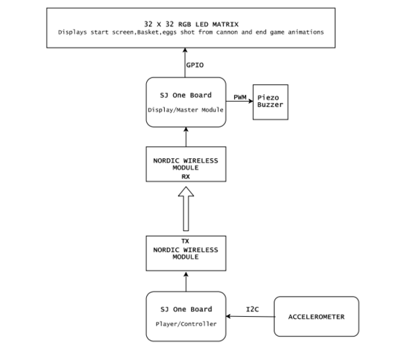
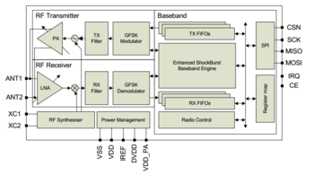
Hardware design diagram above gives an overview of the entire system which consists of the two SJ-One controllers: one board is used as Control Module and other board is used as the Display Module.
- The Control Module uses the onboard accelerometer on SJ-One which is interfaced via I2C protocol. The calibrated accelerometer values are then used to determine the basket position on the LED Matrix.
- The Display Module SJ-One board is used to control a 32*32 RGB LED Matrix.This matrix displays the basket, eggs shot from the cannon.The movement of the basket is as per the orientation value received from the Control Module, through Wireless Module. It also consists of Peizo buzzer which is controlled via PWM pin.
Display Module
RGB LED Matrix:
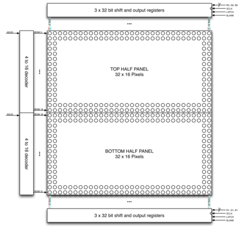
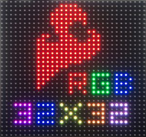
The Human Machine Interface is a display which is composed of 6mm pitch 1024 RGB LEDs arranged in a 32x32 matrix. 32 rows of the matrix is divided into 16 interleaved sections. Here the first section is the 1st and 16th 'row' (32 x 2 = 64 RGB LEDs), the second section is 2nd and 17th 'row' and so on. On the PCB is 12 LED driver chips. These are like 74HC595s but they have 16 outputs and they are constant current. 16 outputs * 12 chips = 192 LEDs that can be controlled at once, and 64 * 3 (R G and B) = 192. So now the design comes together. We can have 192 outputs that can control one line at a time, with each of 192 R, G and B LEDs either on or off. The LPC1758 controller selects which section to currently draw (using A, B, C and D address pins - 4 bits can have 16 values). Once the address is set, the controller clocks out 192 bits of data (24 bytes) and latches it. Then it increments the address and clocks out another 192 bits, etc until it gets to address #15, then it sets the address back to #0. To light up an individual pixel, appropriate row value is loaded on to the address pins A,B,C & D, Clock is set out to traverse the row and when required pixel is reached, the latch is set high to turn ON the LED. The hardware interface to the LED Matrix uses GPIO for all data and control lines. A GPIO clock is toggled to shift in data sitting at the Matrix's 6 data ports.
| SJ One Board Pin | Name | Description |
|---|---|---|
| P0.0 | addrA | Address Input A |
| P0.1 | addrB | Address Input B |
| P2.6 | addrC | Address Input C |
| P2.7 | addrD | Address Input D |
| P1.29 | Latch | Shift in row data/Active High |
| P1.28 | Output Enable | Turn on selected rows/Active Low |
| P1.19 | Clock | Shift clock |
| P1.22 | R1 | Top half red data |
| P0.26 | G1 | Top half green data |
| P1.23 | B1 | Top half blue data |
| P1.30 | R2 | Bottom half red data |
| P1.31 | G2 | Bottom half green data |
| P2.5 | B2 | Bottom half blue data |
Piezo Buzzer:
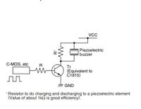
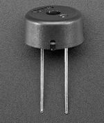
Piezo electric buzzer are high performance buzzer that employ piezoelectric elements and are designed for easy incorporation into various circuits. These buzzers are designed for external excitation, the same part can serve as both a musical tone oscillator and a buzzer. In our project we are using this device to create musical tones by varying the operating frequency.The different range of operating frequency are generated from PWM peripheral. Different range of frequencies are maintained as constants ,these constants are fed to PWM,which generates square wave. The output of the PWM is driving the Piezo buzzer.
Code snippet for creating musical tones by varying frequency:
int fire[]=
{
		550,/*twice the freq of this and use always tempo as 40 */
		404,
		315,
		494,
		182,
		260,
		455,
		387,
		340
};

void fire_sound_level(void){
	 for(int i = 0;i < 8;i++)
		 {
		 	 uint8_t tempo = 40;
		 	 	 while(tempo)
		 	 	 {
					pwm.SetFrequency(fire[i]*2);
					pwm.SetDutyCycle(pwm.k2_1,50);
					pwm.PwmEnableMode(true);
					tempo--;
		 	 	 }
		 }
		 pwm.PwmEnableMode(false);
	}
Control Module
Accelerometer:
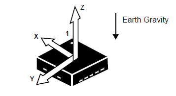
| In our project,we have calibrated the accelerometer based the values of X,Y and Z co-ordinates corresponding to different orientations of the accelerometer to control the horizontal movement of the Basket to catch the eggs on the screen. This has also helped us decide and control the speed of the basket. |
Code snippet for Accelerometer Calibration:
if (((x_coordiante > px_coordiante + CONSOLE_SENSITIVITY) && (x_coordiante <= CONSOLE_TILT_RANGE) ))
{
        boardOrientation=left;
        bskObj.speed=BASKET_SPEED;
        px_coordiante=x_coordiante;
}
    //left
    else if((x_coordiante<px_coordiante-CONSOLE_SENSITIVITY && x_coordiante>=-CONSOLE_TILT_RANGE))
{
        boardOrientation=right;
        bskObj.speed=BASKET_SPEED;
        px_coordiante=x_coordiante;
}
else if(x_coordiante>CONSOLE_TILT_RANGE ){
        boardOrientation=left;
        bskObj.speed=BASKET_SPEED;
}
else if(x_coordiante<-CONSOLE_TILT_RANGE ){
        boardOrientation=right;
        bskObj.speed=BASKET_SPEED;
    }
else
{
        boardOrientation=invalid;
        py_coordiante=y_coordiante;
}
Wireless Module:
Code snippet for Wireless Transmitter:
struct pckt
{
    int16_t x;
    int16_t y;
    int16_t z;
    int16_t buttonPressed=0;
};
void WirelessTx(void *p)
{
       while(1)
       {
           pckt var;
           var.x = AS.getX();/values from accelerometer*/
           var.y = AS.getY();
           var.z = AS.getZ();
           pckt var;
             while(1)
             {
                 if(SW.getSwitch(1))
                 {
                     var.buttonPressed=1;
                     vTaskDelay(300);
                 }
                 else if(SW.getSwitch(2))
                 {
                     var.buttonPressed=2;
                     vTaskDelay(300);
                 }
           wireless_send(REM, mesh_pkt_nack,(pckt*)&var, 8, 0);
           vTaskDelay(50);
             }
       }
}
Code snippet for Wireless Receiver: void wirelessRx(void* p)
{
while(1)
{
mesh_packet_t rcvPkt;
int timeout_ms = 50;
if(wireless_get_rx_pkt(&rcvPkt, timeout_ms)){
iphObj.x_coordiante = (int16_t)(*((uint16_t*)(rcvPkt.data+0)));
iphObj.y_coordiante = (int16_t)(*((uint16_t*)(rcvPkt.data+2)));
iphObj.z_coordiante = (int16_t)(*((uint16_t*)(rcvPkt.data+4)));
iphObj.buttonPressed= (int16_t)(*((uint16_t*)(rcvPkt.data+6)));
if(iphObj.buttonPressed==1 )
{
xSemaphoreGive(playPauseHandler);
}
else if(iphObj.buttonPressed==2 )
{
xSemaphoreGive(resetGameHandler);
}
}
vTaskDelay(50);
}
}Software DesignTasks within LPC Board 1 (LED display): ImplementationPorting Adafruit driver into LPC : Testing & Technical ChallengesIssue #1Porting Adafruit driver into LPC As we used the existing Adafruit library,we had to map the LPC GPIOs to LED matrix pins. Issue #2Piezo Buzzer sound frequency not varying at higher speed. A lot of trials and different frequency combinations were required to make the sound work properly. Issue #3In Nordic Wireless, the transmitted data was received only once despite the transmitter transmitting data continuously. This was because vTaskStartScheduler() API was used by us. The scheduler_start() API was required to be used for Nordic Wireless to function properly. ConclusionConclude your project here. You can recap your testing and problems. You should address the "so what" part here to indicate what you ultimately learnt from this project. How has this project increased your knowledge? Project VideoUpload a video of your project and post the link here. Project Source CodeReferencesAcknowledgementAny acknowledgement that you may wish to provide can be included here. References UsedList any references used in project. [1] Nordic wireless datasheet AppendixYou can list the references you used. |
