Difference between revisions of "F17: FoxP2"
Proj user5 (talk | contribs) |
Proj user5 (talk | contribs) |
||
| Line 1: | Line 1: | ||
| − | [[File:Night FoxP2.jpg|right|FoxP2]] | + | [[File:Night FoxP2.jpg|900|thumb|right|FoxP2]] |
=== Grading Criteria === | === Grading Criteria === | ||
<font color="green"> | <font color="green"> | ||
Revision as of 10:11, 15 December 2017
Contents
Grading Criteria
- How well is Software & Hardware Design described?
- How well can this report be used to reproduce this project?
- Code Quality
- Overall Report Quality:
- Software Block Diagrams
- Hardware Block Diagrams
- Schematic Quality
- Quality of technical challenges and solutions adopted.
FOXP2
Abstract
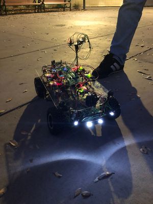
This project entails the aggregated knowledge from the Embedded System courses offered in SJSU, leveraged into a fully functioning self-driving vehicle. This vehicle will navigate the terrain, avoid obstacles, and relay feedback to the user.
Objectives & Introduction
Show list of your objectives. This section includes the high-level details of your project. You can write about the various sensors or peripherals you used to get your project completed.
Team Members & Responsibilities
- R Nikfar
- Team Lead, Electrical Circuits Engineering, PCB design, Sensor testing and implementation.
- Jason Tran
- Sensor IO Implementaion, and testing, Master controller.
- Ahsan Uddin
- Git Admin and Motor Control.
- Yuyu Chen
- GPS module implementation.
- Marvin Flores
- Android Application development and testing.
- Rabeel Elahi
- Master Controller Implementation.
- Sophia Quan
- LCD interface and Motor Control.
- Michael Jaradah
- Unit Testing.
- Taylor Kearns
- Testing.
- Bohan Liu
- Master Controller.
Schedule
Show a simple table or figures that show your scheduled as planned before you started working on the project. Then in another table column, write down the actual schedule so that readers can see the planned vs. actual goals. The point of the schedule is for readers to assess how to pace themselves if they are doing a similar project.
| Week# | Date | End Date | Task | Status | Completion Date | |
|---|---|---|---|---|---|---|
| 1 | 10/8/2017 | 10/14/2017 | Geographical: Order GPS and Compass
Android: Setup Android Studio; Run test application Motor: PWM proof of concept Sensors: Research and requirement for the proper front and reverse sensors. IO design. PCB: Initial design of PCB without peripherals was Completed. Master: Research Self-driving car algorithm. |
Completed
Completed Completed Completed Completed Completed |
Android & Bridge: 10/21/2017 | |
| 2 | 10/15/2017 | 10/21/2017 | Geographical: Interface with micro-controller to receive raw data
Android & Bridge: Initial App UI running. Create a solid plan for checkpoint algorithm. Motor: Run the car in straight line in manual mode. Sensors: Purchase and create the protocols and IO. Master: Start the design of the master controller for all IO. |
Completed
On-going Completed Completed On-going |
Geographical: 10/21/2017 Android & Bridge: 10/28/2017 | |
| 3 | 10/22/2017 | 10/28/2017 | Geographical: Implement algorithm to parse GPS NMEA sentence and calibrate compass
Android & Bridge: Checkpoint algorithm implemented. Phone to SJSUOne board communication setup. Motor: LCD Display initial integration Sensors: Initialize testing and debugging on the sensors. Master: Set priorities for the connected IO, and design a flowchart of the whole system |
Geographical: Completed Android & Bridge: Completed Delayed due to shipping issues |
Geographical: 10/28/2017 Android & Bridge: 11/04/2017 | |
| 4 | 10/29/2017 | 11/04/2017 | Geographical: Integrate GPS and compass together to get heading, bearing, and distance
Android & Bridge: Checkpoint algorithm testing. Full Communication with SJSUOne board implemented. Motor: Implement Speed and Voltage sensor. Full functional motor system that can support Gateway Sensors: Implement the IO and sensors with the master controller. PCB: initial design sent out to be printed. Master: Create and Design the Algorithm to handle IO from sensors and output motor controls. |
Completed
Geographical: Completed Android & Bridge: Completed Master: Completed |
Geographical: 11/04/2017 Android & Bridge: 11/11/2017 | |
| 5 | 11/05/2017 | 11/11/2017 | Geographical: Update DBC with Bridge controller and interface with other nodes on CAN bus
Android & Bridge: Other commands such as start and stop implemented and tested. Checkpoint algorithm finalized. Motor: Implement full functional LCD and Speed sensor feedback control Sensors: Further testing and fine-tuning of sensors for a fluid and seamless drive. Master: Testing of Signals, CAN, and behavior of the vehicle. |
Geographical: On-going Android & Bridge: Completed Master: On-going |
Geographical: 11/11/2017 Android & Bridge: 11/18/2017 | |
| 6 | 11/12/2017 | 11/18/2017 | Geographical: Calibrate compass with car
Motor: Reverse end to end system integration test Android & Bridge: Forward commands to GEO board Sensors: Improve filtering algorithm. Develop proof of concept for TOF sensors. |
Android & Bridge: Completed Motor: Completed |
Geographical: 11/14/2017 Android & Bridge: 11/25/2017 | |
| 7 | 11/19/2017 | 11/25/2017 | Geographical: Checkpoint algorithm
Motor: Speed integration check for final speed settings Android & Bridge: Receive messages from GEO & SENSOR. Add features to the app to display sensor values. Sensors: Compare TOF sensor viability. Look into other forms of measurement such as voltage, etc. |
Android & Bridge: Completed Motor: Completed |
Geographical: 11/25/2017 Android & Bridge: 11/25/2017 | |
| 8 | 11/26/2017 | 12/02/2017 | Geographical: System testing
Motor: Code freeze after feature complete. Clean up and unit test Android & Bridge: Implement auto-connect. Sensors: System testing |
Android & Bridge: Completed Motor: Completed |
Geographical: 12/02/2017 Android & Bridge: 12/02/2017 | |
| 9 | 12/03/2017 | 12/09/2017 | Geographical: System testing
Android & Bridge: Testing Sensors: System testing |
|||
| 10 | 12/10/2017 | 12/16/2017 | Geographical: Testing | Android & Bridge: Testing | ||
| 11 | 12/17/2017 | 12/20/2017 | Demo autonomous car on 12/20 |
Parts List & Cost
Give a simple list of the cost of your project broken down by components. Do not write long stories here.
Overall Design and Methodology
Board Connection Architecture
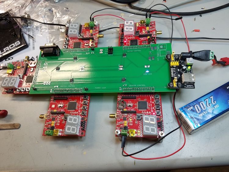
Our team's approach to the design of this project was solely based on the integrity of its connections and communication between the nodes. Each node would handle specific parts of the car that would require an extensive amount of computing. At the center of this communication would be our design and printed PCB(printed circuit board). This board was designed in a manner that would reduce the amount of noise within the circuitry of its components, and place its nodes at an optimal location relative to the car.
Insert Picture of the board connections here
Printed Circuit Board
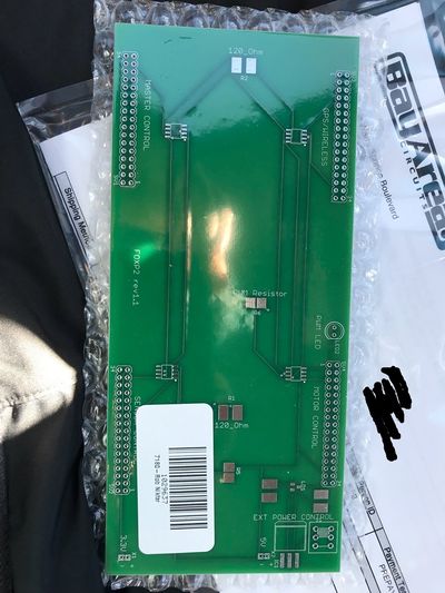
The PCB which is at the heart of this project was designed in Eagle CAD. There were 2 iterations of this board. The first one was designed without validation and had problems with noise within the CAN communications(discussed in problems encountered section). This design lacked several necessary connections and was limited by functionality.
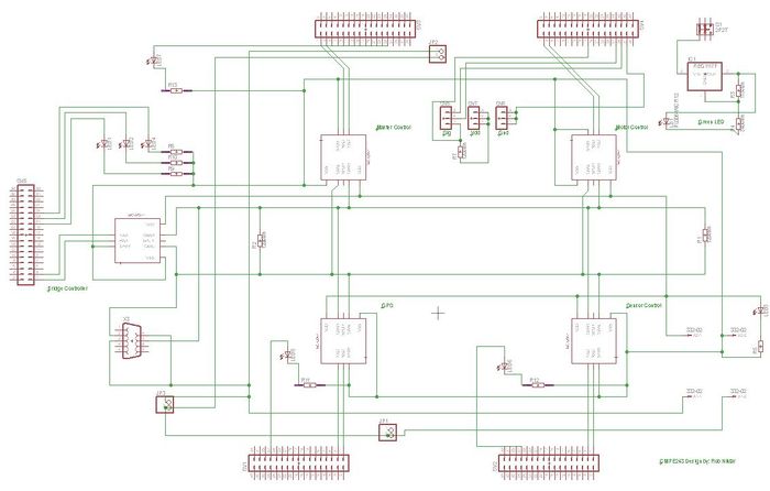
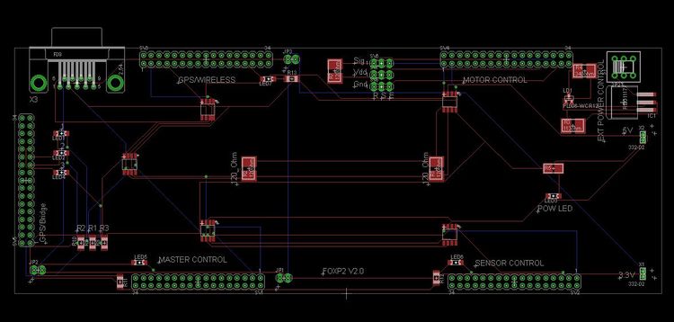
The Second version of the board would incorporate 4 external power outlets that supply 3.3V and 5V to external components as necessary. There would also be an external power unit with regulators that make sure that a clean power is fed to the boards if necessary. As shown in the schematic, the can transceivers are connected to the boards using the terminating resistors. This CAN bus line also connects to the DB9 connections to easily read the CAN data using the PCAN Dongle.
Before the Board was sent for printing, the rat nests had to be removed and the connections had to be routed in such a way that minimum amount of noise was created. this ensured a robust communication for the CAN bus and stable noise-free power supply for the external components such as the Ultrasonic Sensors.
Master Controller (Gateway)
The design section can go over your hardware and software design. Organize this section using sub-sections that go over your design and implementation.
Hardware Design
Discuss your hardware design here. Show detailed schematics, and the interface here.
Hardware Interface
In this section, you can describe how your hardware communicates, such as which BUSes used. You can discuss your driver implementation here, such that the Software Design section is isolated to talk about high level workings rather than inner working of your project.
Software Design
Show your software design. For example, if you are designing an MP3 Player, show the tasks that you are using, and what they are doing at a high level. Do not show the details of the code. For example, do not show exact code, but you may show psuedocode and fragments of code. Keep in mind that you are showing DESIGN of your software, not the inner workings of it.
Implementation
This section includes implementation, but again, not the details, just the high level. For example, you can list the steps it takes to communicate over a sensor, or the steps needed to write a page of memory onto SPI Flash. You can include sub-sections for each of your component implementation.
Motor Controller
Motor Controller primary tasks are as follows: 1. Control the rear wheels for moving forward, backward and stop 2. Control the front wheels to maneuver 3. Display contents on the LCD
Hardware Design
1. ESC
2. Servo
3. RPM Sensor
4. LCD
Hardware Interface
1. CAN bus
2. PWM to Motor and servo
3. RPM sensor for edge detection
4. UART to LCD
In this section, you can describe how your hardware communicates, such as which BUSes used. You can discuss your driver implementation here, such that the Software Design section is isolated to talk about high level workings rather than inner working of your project.
Software Design
1. Init
2. 1 Hz Task
3. 10 Hz task
4. 100 Hz task
Show your software design. For example, if you are designing an MP3 Player, show the tasks that you are using, and what they are doing at a high level. Do not show the details of the code. For example, do not show exact code, but you may show psuedocode and fragments of code. Keep in mind that you are showing DESIGN of your software, not the inner workings of it.
Implementation
This section includes implementation, but again, not the details, just the high level. For example, you can list the steps it takes to communicate over a sensor, or the steps needed to write a page of memory onto SPI Flash. You can include sub-sections for each of your component implementation.
Testing & Technical Challenges
Describe the challenges of your project. What advise would you give yourself or someone else if your project can be started from scratch again? Make a smooth transition to testing section and described what it took to test your project.
Include sub-sections that list out a problem and solution, such as:
<Bug/issue name>
Discuss the issue and resolution.
Conclusion
Conclude your project here. You can recap your testing and problems. You should address the "so what" part here to indicate what you ultimately learnt from this project. How has this project increased your knowledge?
Project Video
Upload a video of your project and post the link here.
Project Source Code
References
Acknowledgement
Any acknowledgement that you may wish to provide can be included here.
References Used
List any references used in project.
Appendix
You can list the references you used.
