Difference between revisions of "F17: Alpha"
Proj user1 (talk | contribs) (→Hardware Interface) |
Proj user1 (talk | contribs) (→Sensor Module) |
||
| Line 272: | Line 272: | ||
'''<insert image of two sensors placed close by so that their beams are overlapping>''' | '''<insert image of two sensors placed close by so that their beams are overlapping>''' | ||
| − | [[File:243_Alpha_Sensorpin_conn.png| | + | [[File:243_Alpha_Sensorpin_conn.png|600x600px|thumb|Pin connections - middle sensor]] |
=== Hardware Interface === | === Hardware Interface === | ||
| Line 286: | Line 286: | ||
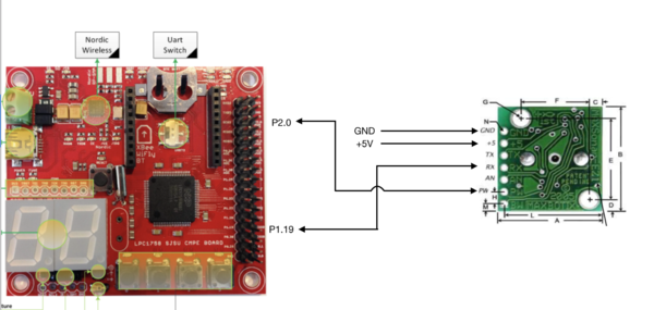
Pin connections for the middle sensor are displayed. | Pin connections for the middle sensor are displayed. | ||
| + | |||
| + | |||
| + | |||
| + | |||
| + | |||
| + | |||
| + | |||
| + | |||
| + | |||
=== Software Design === | === Software Design === | ||
| − | [[File:243_sensormessage_Alpha.png| | + | [[File:243_sensormessage_Alpha.png|600x600px|thumb|Sensor CAN message]] |
As described in the previous section, the sensors are triggered one by one to prevent corruption of data. In our implementation the sensors are triggered in the following order: middle, right, left and back. The back and left sensors are triggered together since they would not interfere with each other. | As described in the previous section, the sensors are triggered one by one to prevent corruption of data. In our implementation the sensors are triggered in the following order: middle, right, left and back. The back and left sensors are triggered together since they would not interfere with each other. | ||
Revision as of 03:17, 10 December 2017
Contents
Project Title
Alpha - Self-navigating RC car using CAN communication based on FreeRTOS.
Git Link - ALPHA
Git Users:
- Anirudh1313
- chhavi17
- DoyalPatel
- jigar29
- kthnptl
- rajvisharia
- ShubhamKulkarni93
- SnehaSharma
- SushmaSJSU
- SuchetaCiyer
Abstract
This section should be a couple lines to describe what your project does.
Objectives & Introduction
Show list of your objectives. This section includes the high level details of your project. You can write about the various sensors or peripherals you used to get your project completed.
Team Members & Responsibilities
- Master Controller
- Jigar Agarwal
- Sucheta Iyer
- Motor Controller
- Raj Visharia
- Shubham Kulkarni
- Geographical Controller
- Krishna Sai Anirudh Katamreddy
- Chhavi Mehta
- Sensor Controller
- Sneha Sharma
- Sushma Macha
- Communication Bridge Controller + LCD
- Kathan Patel
- Android Application
- Doyal Patel
- Sneha Sharma
- Testing
- Doyal Patel
- Jigar Agarwal
- Sucheta Iyer
Schedule
| Week# | Start Date | End Date | Task | Status |
|---|---|---|---|---|
| 1 | 09/15/2017 | 09/16/2017 |
|
Completed |
| 2 | 09/17/2017 | 10/03/2017 |
|
Completed |
| 3 | 10/04/2017 | 10/10/2017 |
|
Completed |
| 4 | 10/11/2017 | 10/17/2017 |
|
Completed |
| 5 | 10/18/2017 | 10/24/2017 |
|
Completed |
| 6 | 10/25/2017 | 10/31/2017 |
|
Completed |
| 7 | 11/01/2017 | 11/07/2017 |
|
Almost Done |
| 8 | 11/08/2017 | 11/14/2017 |
|
To Do |
| 9 | 11/15/2017 | 11/21/2017 |
|
To Do |
| 10 | 11/22/2017 | 11/29/2017 |
|
To Do |
| 11 | 11/30/2017 | 12/14/2017 |
|
To Do |
| **************Final Demonstration.*************** | To Do |
Parts List & Cost
| Item# | Part Desciption | Vendor | Datasheet | Qty | Cost |
|---|---|---|---|---|---|
| 1 | RC Car | 1 | |||
| 2 | CAN Transceivers MCP2551-I/P | Microchip [1] | MCP2551-I/P Datasheet | 8 | Free Samples |
| 3 | Sonar Sensor | Amazon [2] | Maxbotix EZ1 MB 1010 Datasheet | 4 | $24.95 |
| 4 | Headlights | ||||
| 5 | NiMH Battery | ||||
| 6 | Charger for NiMH/NiCd Battery | ||||
| 7 | Character LCD Display |
Sensor Module
The sensor module refers to the sensors and the embedded board that controls the sensors. In this project we have used four Maxbotix EZ0 ultrasonic sensors. Each of these is mounted in four positions. Three sensors face the front of the car and are positioned in the centre, the left edge and right edge of the car. One sensor is mounted on the back of the car.
The main goal of the sensor module is to detect the distance to an obstacle, from the car and provide this information to the driver module so that it can successfully avoid the obstacle.
Hardware Design
The sensors used are LV-MaxSonar-EZ1 Ultrasonic Range Finder MB1010.
The valid sensors output is a value between 6 and 254. This value is in inches and represents the distance to the obstacle, from the sensor. It is to be noted that if the obstacle is closer than 6 inches from the sensor it will not be detected.
The sensor provides output in three forms; As a pulse on the PW pin, where pulse width represents the distance to obstacle; As an analog voltage on the AN pin; As a digital output on the TX pin, in RS-232 format. We have used the PW pin in this project to receive the input from the sensor.
It is to be noted that if two sensors which are placed so that their beams/detection areas overlap, are ranging at the same time, they cause each other interference and hence incorrect values. Hence we trigger each sensor separately one by one so that at any time, only one sensor is ranging.
<insert image of sensor here. mark all the pins - vcc gnd tx rx pw> <insert image of two sensors placed close by so that their beams are overlapping>
Hardware Interface
Pin connections for each sensor is as follows:
PW (Pin 2) - GPIO Pin configured as interrupt to receive input from sensor
RX (Pin 4) - GPIO Pin configured as output to trigger the sensor
VCC (Pin 6) - +5V
GND (Pin 7) - GND
Pin connections for the middle sensor are displayed.
Software Design
As described in the previous section, the sensors are triggered one by one to prevent corruption of data. In our implementation the sensors are triggered in the following order: middle, right, left and back. The back and left sensors are triggered together since they would not interfere with each other.
Every sensor needs a power up time of 250 ms and some time to calibrate and take the first reading. After this period the sensor can provide a reading every 49 ms. In our implementation, all 4 sensor values are taken every 120 ms and put on the CAN bus. The format of the CAN message is shown in the following snippet taken from the DBC file. It can be observed that the sensor message has a high priority since it is critical to the operation of the car.
Implementation
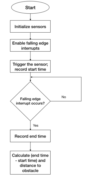
The following steps are followed to get a valid sensor reading.
1. Initialize the sensors - account for power up and calibration delay.
2. Enable falling edge interrupts and setup callback functions - this is to record the pulse width output of the sensor
3. Trigger each sensor and record the current time. This is the start time.
4. When falling edge interrupt occurs record the time. This is the end time.
5. Calculate pulse width using the start and end time. This pulse width would indicate the distance to the obstacle.
Testing & Technical Challenges
There were a few difficulties during implementation and testing of the sensors. Lessons learned include the following:
1. Research different types of sensors, find out the strengths and weaknesses of each before making a decision.
2. Ultrasonic sensors need to be slightly tilted upwards when mounted on the car to prevent them from accidentally detecting ground as an obstacle. This becomes especially necessary when testing on a slope/ramp.
3. Ultrasonic sensors are very sensitive and care needs to be taken while soldering them. Accidental overheating can cause them to be destroyed.
4. The ultrasonic sensors provide more range when +5V is used as supply rather than +3.3V.
5. Testing both indoors and outdoors is necessary to check if the sensor readings are accurate in both conditions.
Geographical Controller
The design section can go over your hardware and software design. Organize this section using sub-sections that go over your design and implementation.
Hardware Design
Discuss your hardware design here. Show detailed schematics, and the interface here.
Hardware Interface
In this section, you can describe how your hardware communicates, such as which BUSes used. You can discuss your driver implementation here, such that the Software Design section is isolated to talk about high level workings rather than inner working of your project.
Software Design
Show your software design. For example, if you are designing an MP3 Player, show the tasks that you are using, and what they are doing at a high level. Do not show the details of the code. For example, do not show exact code, but you may show psuedocode and fragments of code. Keep in mind that you are showing DESIGN of your software, not the inner workings of it.
Implementation
This section includes implementation, but again, not the details, just the high level. For example, you can list the steps it takes to communicate over a sensor, or the steps needed to write a page of memory onto SPI Flash. You can include sub-sections for each of your component implementation.
Testing & Technical Challenges
Describe the challenges of your project. What advise would you give yourself or someone else if your project can be started from scratch again? Make a smooth transition to testing section and described what it took to test your project.
Include sub-sections that list out a problem and solution, such as:
<Bug/issue name>
Discuss the issue and resolution.
Conclusion
Conclude your project here. You can recap your testing and problems. You should address the "so what" part here to indicate what you ultimately learnt from this project. How has this project increased your knowledge?
Project Video
Upload a video of your project and post the link here.
Project Source Code
References
Acknowledgement
Any acknowledgement that you may wish to provide can be included here.
References Used
List any references used in project.
Appendix
You can list the references you used.


