F15: TopGun
Contents
- 1 Grading Criteria
- 2 Project Title
- 3 Abstract
- 4 Objectives & Introduction
- 5 Schedule
- 6 Parts List & Cost
- 7 Design & Implementation
- 8 Sensor Controller
- 9 Geographical Controller
- 10 Motor I/O Controller
- 11 Master Controller
- 12 Bluetooth/Bridge Controller
- 13 DBC File Implementation
- 14 Testing & Technical Challenges
- 15 Conclusion
- 16 References
Grading Criteria
- How well is Software & Hardware Design described?
- How well can this report be used to reproduce this project?
- Code Quality
- Overall Report Quality:
- Software Block Diagrams
- Hardware Block Diagrams
- Schematic Quality
- Quality of technical challenges and solutions adopted.
Project Title
This is Top Gun - The super car that drives by itself!
Abstract
The GPS-controlled automated RC car will consistes of 5 different LPC 1758 controllers. Each controller will have a specific major tasks required to drive the car. The naming convention goes as:- Motor & I/O controller - this will control the motors of the car and will also connected with a LCD display to show the car's status, Sensor controller - It will be connected to the obstacle detecting sensors on the car, Communication Bridge - It will be connected to an Android mobile phone so as to provide co-ordinates, GEO controller - This will give the exact orientation of the car e.g., heading & bearing, etc. and finally the Master controller - This will collect the data from other controllers and will guide the motor controller. These controllers are connected using CAN bus. After the final implementation, this car will be capable of driving by itself using the destination co-ordinates set by us avoiding every obstacles, overcoming slopes thereby reaching the destination safely!
Objectives & Introduction
Show list of your objectives. This section includes the high level details of your project. You can write about the various sensors or peripherals you used to get your project completed.
Team Members & Responsibilities
Communication Bridge & Android Controller:
- Anush Shankar
- Aditya Devaguptapu
Geographical Controller:
- Chitrang Talaviya
- Navjot Singh
Master Controller:
- Hemanth Konanur Nagendra
- Akshay Vijaykumar
Sensor Controller:
- Divya Dodda
- Dhruv Kakadiya
Treasurer:
- Anuj Korat
Five Controllers Used
- Master Controller
- Motor I/O Controller
- Sensor Controller
- Geographical Controller
- Bluetooth/Bridge Controller
Schedule
Show a simple table or figures that show your scheduled as planned before you started working on the project. Then in another table column, write down the actual schedule so that readers can see the planned vs. actual goals. The point of the schedule is for readers to assess how to pace themselves if they are doing a similar project.
Team Schedule
| SI No. | Start Date | End Date | Task | Status | Actual Completion Date |
|---|---|---|---|---|---|
| 1 | 09/15/2015 | 09/27/2015 |
|
Completed | 09/27/2015 |
| 2 | 09/27/2015 | 10/30/2015 | Following up on RC car and other component procurement through team discussions | Completed | 10/30/2015 |
| 3 | 10/30/2015 | 10/06/2015 | Hardware design of the car including discussions on component placement, soldering and wiring. | Completed | 10/06/2015 |
| 4 | 10/06/2015 | 10/17/2015 | CAN message ID's, priorities, data size and format proposals for all the possible CAN messages on the bus | Completed | 10/20/2015 |
| 5 | 10/20/2015 | 11/05/2015 | Discussions and proposals on basic obstacle avoidance algorithm with sensor integration, hands on and testing | Completed | |
| 6 | 11/05/2015 | 11/25/2015 | Integrating other modules and components to the RC car, development of autonomous driving algorithm and finalize on hardware layout of the car | Incomplete | |
| 7 | 11/25/2015 | 12/15/2015 | Testing the RC car in real world environments | Incomplete |
Parts List & Cost
Design & Implementation
The design section can go over your hardware and software design. Organize this section using sub-sections that go over your design and implementation.
CAN Message ID Table
| Message ID | Task associated with ID | Data bit-fields |
|---|---|---|
| 0x00 | Kill Switch | No Data |
| 0x01 | Reset |
reset_motorio:8; // Acknowledge motorio controller reset_sensor:8; // Acknowledge sensor controller reset_geo:8; // Acknowledge geo controller reset_bluetooth:8; // Acknowledge bluetooth module |
| 0x02 | Master Sync Ack |
ack_motorio:8; // Acknowledge motorio controller ack_sensor:8; // Acknowledge sensor controller ack_geo:8; // Acknowledge geo controller ack_bluetooth:8; // Acknowledge bluetooth module |
| 0x03 | MotorIO Controller Sync | No Data |
| 0x04 | Sensor Controller Sync | No Data |
| 0x05 | Bluetooth Controller Sync | No Data |
| 0x06 | Geo Controller Sync | No Data |
| 0x07 | MotorIO controller Heart-beat | No Data |
| 0x08 | Sensor controller Heart-beat | No Data |
| 0x09 | Bluetooth controller Heart-beat | No Data |
| 0x0A | Geo controller Heart-beat | No Data |
| 0x0B | Run mode | mode:8; |
| 0x0C | Distance Sensor Data |
front_left:8; // Front left sensor reading front_right:8; // Front right sensor reading front_center:8; // Front centre sensor reading left:8; // Left sensor reading right:8; // Right sensor reading back:8; // Back sensor reading |
| 0x0D | MotorIO Direction Data |
speed:8; // Indicate speed for DC motor turn:8; // Indicate turn angle for servo motor |
| 0x0E | Check-point Request Message | No Data |
| 0x0F | Check-point Start Message |
num_of_points; // Number of check-points to be loaded |
| 0x10 | Check-point Data |
float latitude; float longitude; |
| 0x11 | Geo-Controller New Destination Data |
float latitude; float longitude; |
| 0x12 | Geo-Controller Speed and Angle message |
speed:8; // Speed as measured by the GPS sensor heading:16; // Heading from the Geo controller bearing:16; // Bearing calculated by the Geo controller |
| 0x13 | Geo-Controller Location Data |
float latitude; float longitude; |
| 0x14 | Light and Battery Sensor Data |
light_sensor:8; // Light sensor reading batt_sensor:8; // Battery level sensor reading |
Implementation
This section includes implementation, but again, not the details, just the high level. For example, you can list the steps it takes to communicate over a sensor, or the steps needed to write a page of memory onto SPI Flash. You can include sub-sections for each of your component implementation.
Sensor Controller
Sensor Controller Schedule
| SI No. | Start Date | End Date | Task | Status | Actual Completion Date |
|---|---|---|---|---|---|
| 1 | 09/20/2015 | 09/27/2015 | Researching and ordering the sensors to be used in the project | Completed | 9/27/2015 |
| 2 | 09/27/2015 | 10/03/2015 |
|
Completed | 10/03/2015 |
| 3 | 10/03/2015 | 10/10/2015 | Interfacing ADC ultrasonic sensor to SJOne board, reading sensor values and filter the readings | Completed | 10/10/2015 |
| 4 | 10/10/2015 | 10/20/2015 | Understanding inertial measurement unit sensor, interfacing it to SJOne board to get filtered readings | Completed | 10/20/2015 |
| 5 | 10/20/2015 | 11/05/2015 | Integrating multiple sensors to the SJOne board, testing the sensors and debugging issues | Incomplete | |
| 6 | 11/05/2015 | 11/25/2015 | Preparing sensor values to be sent over CAN bus and testing out the correctness of sensor can messages | Incomplete | |
| 7 | 11/25/2015 | 12/15/2015 | Testing of code during final phases, modifying code in cooperation with other teams and optimization of code | Incomplete |
Sensor Testing
HCSR04 Sensor Testing
- As shown in the figure below, HC-SR04 ultrasonic sensor requires an external 5V DC supply.
- When in the initial testing stage we just connected one sensor for testing the accuracy and the range of the sensor.
- The values we received were very stable and neat.

Parallax Ping Sensor Testing
- As shown in the figure below, Parallax ping ultrasonic sensor requires an external 5V DC supply.

Finalizing distance sensors
- Both sensors being pretty accurate, we were confused while finalizing one. So we were using both sensors, for front we were using Parallax and for left,right and back sensors we were using HCSR04 sensor.
- HCSR04 sensor was better option because as it was much cost efficient than the Parallax Ping Sensor (Where one Parallax Ping costs $30, one HCSR04 costed us only $2)
- Its only drawback is, the cheaper one sensor needed good filter to remove some spikes and Parallax sensor was working pretty good without any filtering.
Switching to Hardware Timer
- Previously, all sensor were triggered using software timers. We declared a soft timer for each sensor which kept track of the time between trigger and echo for that particular sensor.
- If we see the declaration of software timer as shown below, we come to know that the timer returns a value in milliseconds.
inline uint64_t getTargetTimerValueMs(void) const { return mTargetMs; }
- If we apply the before mentioned distance formula to this timer value in milliseconds, we will always get the distance in multiples of 17.
- Let's work out an example for better understanding;

- As the return return type of this function is an integer, we always get the distance in multiples of 17, which compromises the accuracy by a large factor.
- Because of this reason we switched to hardware timers.
- The declaration of hardware timer is as shown below, and this return value of time is in micro-seconds.
   uint32_t lpc_timer_get_value(const lpc_timer_t timer)
   {
       return (lpc_timer_get_struct(timer)->TC);
   }
- Let's work out the same example for the return value being 1usec.

- Hence, even if the timer value is an integer, as it is in microseconds, we have improved the accuracy.
- As there are only three hardware timers in LPC 1768 we cannot allot individual timer for each sensor. Hence, we use just one hardware timer which runs regardless any individual sensor.
- All sensors get the current timer value during trigger and echo from this single timer, and do the further processing individually.
Sequentially Triggering of Sensors
- We used to trigger all the sensors at the same time, which caused interference between adjacent sensors, which in turn caused mis-firing of echo.
- This resulted in incorrect distance values from all the sensors.
- Thus to solve this issue, we implemented sequential triggering.
- Under this logic, each sensor will be triggered only when the previous sensor receives an echo or exceeds the maximum echo reception wait time which is 60msec.
- This implementation solved the issue at hand but gave rise to a new issue which is mentioned in the next section.
Limiting the Scope to Improve Frequency
- As discussed in the previous section, if we implement sequential triggering for each sensor, if there is no obstacle, then the worst case delay would be 360 msec(60msec*6sensors) to update all sensor values to the master.
- Means the frequency of communicating these values to the master will be, 2.8Hz.
- For proper obstacle avoidance, we need to provide the sensor data to the master atleast 10 times per second, i.e. at 10Hz.
- Which means data from all six sensors must be calculated within 100msec.
- Even if we consider limiting the time allotted to a sensor to time required for maximum distance (400cms), we will require 23.5msec each sensor i.e. 141msec to update the values of all six sensors. This increases the frequency to 7.1Hz.
- This led is to the solution to this problem, if we limit the scope of each sensor then we can update the sensor values more frequently to the master.
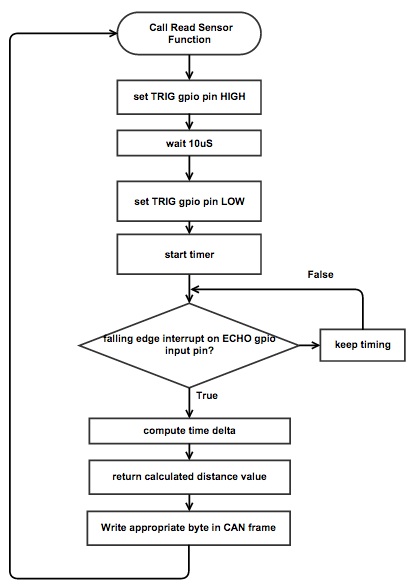
- To overcome this issue, we limited the maximum scope of the sensor to 170 cms, limiting the time required to get the echo to 10msec. Which makes the total time required to calculate all six sensors' data about 60msec.
- Hence, as shown in the flowchart, each sensor waits 10msec for an echo. If we get an echo within 10msec, we calculate the distance; if we don't, we assume the obstacle is at 170cms or further.
Misfiring of Sensor
- At times the sensor used to mis-fire. Which means; in a stable condition, if the obstacle is at a constant distance of 150cms, 1 out of 50 continuous values will be 60cms.
- This value being false, misguides the master.
- To overcome this issue, we introduced a threshold value called DELTA (say, 10cms). Which defines the acceptable range from the previous value.
- In this algorithm, an abrupt change in the distance value should be constant for at least two consecutive reads to be considered genuine.
- If the current value from the sensor is in the range of the previous value's +/- 10cms, then this value is considered to be correct, and is provided to the master. Then this current value will be copied in the previous value register.
- If the current value is not is the previous value's +/- DELTA range then it is considered as a misfire and hence is not provided to the master. But this sudden change might be because of a sudden obstacle; hence, the value is copied in the previous value register, and if the same value repeats, it will be considered genuine and provided to the master.
- The code for this algorithm is as shown below;
       if(temp-DELTA<current && current<temp+DELTA){
           distance = current;
       }
       temp = current;
- Hence, this algorithm will overcome the abrupt mis-firing of the sensor and make the data provided to the master more reliable.
Sensor Software Design
Sensor Controller Team Software Design
Sensor software design is composed of three crucial tasks, which are to read GPIO based sonar, read ADC based sonar, and CAN TX.
GPIO based read:

ADC based read:

CAN Frame write:

Sensor Pin Connections
| Line Item# | Node A Source | Node A Pin | Node B Source | Node B Pin | Description |
|---|---|---|---|---|---|
| 1 | 3.3V Power Supply | 3.3V | SJOne Board | 3V3 | SJOne Power |
| 2 | 3.3V Power Supply | GND | SJOne Board | GND | SJOne Ground |
| 3 | CAN Transceiver | Tx | SJOne Board | P0.1 (Tx) | SJOne - CAN Tx |
| 4 | CAN Transceiver | Rx | SJOne Board | P0.0 (Rx) | SJOne - CAN Rx |
| 5 | CAN Transceiver | 3.3V | 3.3V Power Supply | 3.3V | SJOne - CAN Power |
| 6 | CAN Transceiver | Ground | 3.3V Power Supply | GND | SJOne - CAN Ground |
| 7 | Parallax Ultrasonic Sensor (Front Left) | Vcc | 5V Power Supply | +5V | Front Left Sensor Power |
| 8 | Parallax Ultrasonic Sensor (Front Left) | GND | 5V Power Supply | GND | Front Left Sensor GND |
| 9 | Parallax Ultrasonic Sensor (Front Left) | Echo/Trig | SJOne Board | P2.0 | Front Left Sensor Echo |
| 10 | Parallax Ultrasonic Sensor (Front Right) | Vcc | 5V Power Supply | +5V | Front Right Sensor Power |
| 11 | Parallax Ultrasonic Sensor (Front Right) | GND | 5V Power Supply | GND | Front Right Sensor GND |
| 12 | Parallax Ultrasonic Sensor (Front Right) | Echo/Trig | SJOne Board | P2.2 | Front Right Sensor Echo |
| 13 | Parallax Ultrasonic Range Sensor (Front Middle) | Vcc | 5V Power Supply | +5V | Front Middle Sensor Power |
| 14 | Parallax Ultrasonic Range Sensor (Front Middle) | GND | 5V Power Supply | GND | Front Middle Sensor GND |
| 15 | Parallax Ultrasonic Range Sensor (Front Middle) | Echo | SJOne Board | P2.4 | Front Middle Sensor Echo |
| 16 | Parallax Ultrasonic Range Sensor (Front Middle) | Trig | SJOne Board | P2.5 | Front Middle Sensor Trig |
| 17 | HC-SR04 Ultrasonic Sensor (Left) | Vcc | 5V Power Supply | +5V | Left Sensor Power |
| 18 | HC-SR04 Ultrasonic Sensor (Left) | GND | 5V Power Supply | GND | Left Sensor GND |
| 19 | HC-SR04 Ultrasonic Sensor (Left) | Echo | SJOne Board | P2.6 | Left Sensor Echo |
| 20 | HC-SR04 Ultrasonic Sensor (Left) | Trig | SJOne Board | P2.7 | Left Sensor Trig |
| 21 | HC-SR04 Ultrasonic Sensor (Right) | Vcc | 5V Power Supply | +5V | Right Sensor Power |
| 22 | HC-SR04 Ultrasonic Sensor (Right) | GND | 5V Power Supply | GND | Right Sensor GND |
| 23 | HC-SR04 Ultrasonic Sensor (Right) | Echo | SJOne Board | P2.8 | Right Sensor Echo |
| 24 | HC-SR04 Ultrasonic Sensor (Right) | Trig | SJOne Board | P2.9 | Right Sensor Trig |
| 25 | CAN Transceiver | CANL | CAN BUS | CANL | CANL to CAN BUS |
| 26 | CAN Transceiver | CANR | CAN BUS | CANR | CANR to CAN BUS |
Geographical Controller
Geographical Controller Schedule
| SI No. | Start Date | End Date | Task | Status | Actual Completion Date |
|---|---|---|---|---|---|
| 1 | 09/20/2015 | 09/27/2015 | Researching and ordering the parts | Completed | 9/27/2015 |
| 2 | 09/27/2015 | 10/05/2015 | Studying module data sheets and writing code sketches to be used when modules are procured(GPS and compass) | Completed | 10/05/2015 |
| 3 | 10/05/2015 | 10/15/2015 | Interfacing GPS module and compass to SJOne board and get consistent filtered readings | Incomplete | |
| 4 | 10/15/2015 | 10/30/2015 | Proposals for heading and distance calculation, unit testing and integrating modules | Incomplete | |
| 5 | 10/30/2015 | 11/10/2015 | Calibration of compass and GPS readings, CAN bus communication from geo controller to other boards | Incomplete | |
| 6 | 11/10/2015 | 11/25/2015 | Android application connection with data reception and transmit | Incomplete | |
| 7 | 11/25/2015 | 12/15/2015 | Final phase testing and optimization, collaborating with android team to get better reliable outcomes | Incomplete |
Geographical Controller Hardware Design Components
|
Adafruit MTK3339 GPS:
We chose this part because it provided the base functionality we needed along with many other functions that would be fun to play with and try to include in the project. The antennae options and voltage regulator were also very enticing. |
|

Motor I/O Controller
Team Members:
*Anuj Korat
*Dhruv Kakadiya
Motor & I/O Controller Schedule
| SI No. | Start Date | End Date | Task | Status | Actual Completion Date |
|---|---|---|---|---|---|
| 1 | 09/20/2015 | 09/27/2015 | Researching and ordering the LCD module to be used in the project | Completed | 9/27/2015 |
| 2 | 09/27/2015 | 10/05/2015 |
|
Completed | 10/05/2015 |
| 3 | 10/05/2015 | 10/12/2015 |
|
Completed | 10/12/2015 |
| 4 | 10/12/2015 | 10/30/2015 |
|
Completed | |
| 5 | 10/30/2015 | 11/12/2015 | Proposals related to speed controls and sensors for the same and integration of LCD module(with data display) | Incomplete | |
| 6 | 11/12/2015 | 11/25/2015 | CAN bus communication from motor and I/O controller to other boards | Completed | |
| 7 | 11/25/2015 | 12/15/2015 | Debugging issues during trial runs and testing out fault cases | Incomplete |
I/O Software Design
The I/O Software is based off of two tasks: The Event Handler Task and the RX Task.
Event Handler Task (High Priority):
This Task receives any immediate messages sent from the uLCD, processes the message, and sends the message to the CAN BUS.
This task enables the system to: Turn On/Off the Vehicle and Change Vehicle Modes.
RX Task (Low Priority):
This task receives all messages from the CAN BUS, and outputs message data onto the uLCD
High Level IO Software Logic

Event Handler Task Logic

RX Task Logic

Master Controller
Master Controller Schedule
| SI No. | Start Date | End Date | Task | Status | Actual Completion Date |
|---|---|---|---|---|---|
| 1 | 10/10/2015 | 10/20/2015 |
|
Completed | 10/20/2015 |
| 2 | 10/21/2015 | 10/31/2015 |
|
Completed | 10/25/2015 |
| 3 | 10/26/2015 | 11/01/2015 |
|
Completed | 11/01/2015 |
| 4 | 11/10/2015 | 11/20/2015 |
|
Completed | 11/20/2015 |
| 5 | 10/21/2015 | 11/30/2015 |
|
Incomplete | |
| 6 | 12/01/2015 | 12/07/2015 |
|
Incomplete | |
| 7 | 12/08/2015 | 12/15/2015 | Extensive testing and smoothing out speed, turning, etc | Incomplete |
The Master Controller receives obstacle information from the Sensor Controller, navigation data from the Geo Controller and routing information from the Bluetooth Controller, collates all this information and provides driving directions to the Motor Controller.
Design
Master Controller Team Hardware Design

Master Pin Connections
| Line Item# | Node A Source | Node A Pin | Node B Source | Node B Pin | Description |
|---|---|---|---|---|---|
| 1 | 3.3V Power Supply | 3.3V | SJOne Board | 3V3 | SJOne Power |
| 2 | 3.3V Power Supply | GND | SJOne Board | GND | SJOne Ground |
| 3 | CAN Transceiver | CAN Tx | SJOne Board | P0.1 (Tx) | SJOne - CAN Tx |
| 4 | CAN Transceiver | CAN Rx | SJOne Board | P0.0 (Rx) | SJOne - CAN Rx |
| 5 | CAN Transceiver | CAN 3.3V | 3.3V Power Supply | 3.3V | SJOne - CAN Power |
| 6 | CAN Transceiver | CAN Ground | 3.3V Power Supply | GND | SJOne - CAN Ground |
| 7 | CAN Transceiver | CANL | CAN BUS | CANL | CANL to CAN BUS |
| 8 | CAN Transceiver | CANR | CAN BUS | CANR | CANR to CAN BUS |
Control Flow
On boot-up, Master Controller first attempts to sync with all the other controllers through a power-up sync and acknowledgement handshake mechanism. Once sync is established with all the controllers, it periodically monitors the heart-beat signals from all the controllers till the end of power cycle. If any controller goes out of sync, the master requests that controller to reset itself.
The Master Controller now enters the ‘stopped’ state where no driving takes place. It continuously monitors the CAN bus for any routes from the Bluetooth Controller. Once all the navigation check points have been received, the Master Controller starts driving the car by directing the Motor Controller based on the Geo controller data. While driving, the Master Controller continuously listens for the obstacle data from the Sensor Controller and avoids any obstacles, if necessary. Once obstacle avoidance has been completed, Master makes any necessary course corrections and proceeds towards the destination as per the route.
Communication between Controllers
Power-up Sync and Acknowledgement
Once master boots up, it continuously monitors the CAN bus for a “Power up Sync” message from each of the other controllers. Once it receives the Sync message from all the controllers it acknowledges all of them at once by sending the “Master Sync Ack” message. This should prompt the other controllers to spawn their periodic tasks and start their respective functionalities.
Heart Beat Implementation
After sending the ACK message the master proceeds to spawn its own periodic scheduler and starts monitoring the heartbeat signals from all the controllers at a rate of 1Hz.
Every 1Hz, all the controllers are expected to send their respective “Heart-beat” message over the CAN bus. If this message fails to arrive, the master controller will wait for a specific period of time for the other controller to sync again. The sensor controller and motorIO controllers are very critical components for driving the car. So, they are not allowed to skip any heart-beats. The other controllers have varying thresholds of wait time, allowing them to sync with the master again. Once the threshold time is crossed, the master controller issues a “Reset” message for the controller that went out of sync. The receiving controller is expected to reset and sync again at this point.
If the sensor controller or motor controller go out of sync, the master stops issuing driving directions to the motorIO controller, hence stopping the car.
Data Communication
The master controller performs the following data transactions over the CAN bus.
Bluetooth controller signals to the master controller that a new route has been requested from the Android application through “Check-Point Send” message. In this message, the Bluetooth controller also specifies the number of check-points that are present along the route. The master acknowledges this signal through “Check-point Request” message. The Bluetooth controller starts sending the check-points periodically, at 10Hz, after it receives the ack. The master stores all these check-points in an array and switches to navigation mode.
In navigation mode, master controller issues the next immediate check-point to the Geo controller through “Geo location update” message and expects the current heading, current bearing, current speed and current GPS location information from the Geo controller with respect to this new checkpoint. Master controller continuously calculates the distance between the current GPS location and the current checkpoint location to determine if the checkpoint has been reached. Once reached, the next checkpoint co-ordinates are issued to the Geo controller. This cycle is repeated till the destination has been reached.
All through the navigation mode, master controller directs the motor controller to drive (speed and direction to turn) based on heading and bearing information from the Geo controller. The obstacle information is also being continuously received from the sensor controller. If an obstacle is detected, the master controller stops navigating to the checkpoint and avoids the obstacle. Once obstacle has been avoided the master goes back to navigation.
Driving Algorithm
Overview
Obstacle Avoidance Algorithm
Bluetooth/Bridge Controller
Communication bridge & Android Controller Schedule
| SI No. | Start Date | End Date | Task | Status | Actual Completion Date |
|---|---|---|---|---|---|
| 1 | 09/20/2015 | 09/30/2015 | Getting familiarized with Android SDK, Java, Bluetooth API and Google Maps API | Completed | 09/30/2015 |
| 2 | 09/31/2015 | 10/10/2015 |
|
Completed | 10/10/2015 |
| 3 | 10/10/2015 | 10/22/2015 |
|
Completed | 10/22/2015 |
| 4 | 10/22/2015 | 10/30/2015 | Interfacing bluetooth module to SJOne board through UART and receive data on SJOne board sent by the bluetooth application | Incomplete | |
| 5 | 10/30/2015 | 11/10/2015 | Relay commands and CAN messages from SJOne to android application and test correctness of data | Incomplete | |
| 6 | 11/10/2015 | 11/22/2015 | Performing correct routing between source and destination, have a complete working application, basic testing of application and bridge interface | Incomplete | |
| 7 | 11/22/2015 | 12/15/2015 | Extensive Testing of application during final phases, modifying code in cooperation with other teams and optimization of android application | Incomplete |
DBC File Implementation
- This section explains DBC file implementation of the project. The DBC implementation contains the python based DBC file parser, a DBC file and auto generated C code for the five CAN nodes. These five nodes include driver(master), sensor, motor, geo and bluetooth node. The DBC file is a input to the python DBC parser script. The python script will generate a C file for the specific node given by the user at the command line argument. The python script goes through this DBC file and generates code to marshal (covert to raw CAN) and unmarshal (convert from raw CAN) using the provided API that you can enclose in a header file.
- The following is the DBC file of the project.
     VERSION ""
      NS_ :
           NS_DESC_
           CM_
           BA_DEF_
           BA_
           VAL_
           CAT_DEF_
           CAT_
           FILTER
           BA_DEF_DEF_
           EV_DATA_
           ENVVAR_DATA_
           SGTYPE_
           SGTYPE_VAL_
           BA_DEF_SGTYPE_
           BA_SGTYPE_
           SIG_TYPE_REF_
           VAL_TABLE_
           SIG_GROUP_
           SIG_VALTYPE_
           SIGTYPE_VALTYPE_
           BO_TX_BU_
           BA_DEF_REL_
           BA_REL_
           BA_DEF_DEF_REL_
           BU_SG_REL_
           BU_EV_REL_
           BU_BO_REL_
           SG_MUL_VAL_
BS_:
BU_: NOONE SENSOR DRIVER MOTORIO BLUETOOTH GEO
BO_ 0 DRIVER_KILL_SWITCH: 0 DRIVER
 SG_ DRIVER_KILL_SWITCH_cmd 		: 0|0@1+ (1,0) [0|0] "" SENSOR,MOTORIO,BLUETOOTH,GEO
BO_ 1 DRIVER_RESET: 0 DRIVER
 SG_ DRIVER_RESET_cmd 				: 0|0@1+ (1,0) [0|0] "" SENSOR,MOTORIO,BLUETOOTH,GEO
BO_ 2 DRIVER_SYNC_ACK: 0 DRIVER
 SG_ DRIVER_SYNC_ACK_cmd 			: 0|0@1+ (1,0) [0|0] "" SENSOR,MOTORIO,BLUETOOTH,GEO
BO_ 3 MOTORIO_SYNC: 0 MOTORIO
 SG_ MOTORIO_SYNC_cmd 				: 0|0@1+ (1,0) [0|0] "" DRIVER
BO_ 4 SENSOR_SYNC: 0 SENSOR
 SG_ SENSOR_SYNC_cmd 				: 0|0@1+ (1,0) [0|0] "" DRIVER
BO_ 5 BLUETOOTH_SYNC: 0 BLUETOOTH
 SG_ BLUETOOTH_SYNC_cmd 			: 0|0@1+ (1,0) [0|0] "" DRIVER
BO_ 6 GEO_SYNC: 0 GEO
 SG_ GEO_SYNC_cmd 					: 0|0@1+ (1,0) [0|0] "" DRIVER
BO_ 7 MOTORIO_HEARTBEAT: 0 MOTORIO
 SG_ MOTORIO_HEARTBEAT_cmd 			: 0|0@1+ (1,0) [0|0] "" DRIVER
BO_ 8 SENSOR_HEARTBEAT: 0 SENSOR
 SG_ SENSOR_HEARTBEAT_cmd 			: 0|0@1+ (1,0) [0|0] "" DRIVER
BO_ 9 BLUETOOTH_HEARTBEAT: 0 BLUETOOTH
 SG_ BLUETOOTH_HEARTBEAT_cmd 		: 0|0@1+ (1,0) [0|0] "" DRIVER
BO_ 10 GEO_HEARTBEAT: 0 GEO
 SG_ GEO_HEARTBEAT_cmd 				: 0|0@1+ (1,0) [0|0] "" DRIVER
BO_ 11 MOTORIO_RUNMODE: 1 DRIVER
 SG_ MOTORIO_RUNMODE_cmd 			: 0|8@1+ (1,0) [0|3] "" MOTORIO
BO_ 12 SENSOR_SONARS: 6 SENSOR
 SG_ SENSOR_SONARS_front_left 		: 0|8@1+ (1,0) [0|4] "" DRIVER,MOTORIO
 SG_ SENSOR_SONARS_front_right 		: 8|8@1+ (1,0) [0|4] "" DRIVER,MOTORIO
 SG_ SENSOR_SONARS_front_center 	: 16|8@1+ (1,0) [0|4] "" DRIVER,MOTORIO
 SG_ SENSOR_SONARS_left 			: 24|8@1+ (1,0) [0|4] "" DRIVER,MOTORIO
 SG_ SENSOR_SONARS_right 			: 32|8@1+ (1,0) [0|4] "" DRIVER,MOTORIO
 SG_ SENSOR_SONARS_back 			: 40|8@1+ (1,0) [0|4] "" DRIVER,MOTORIO
BO_ 13 MOTORIO_DIRECTION: 2 DRIVER
 SG_ MOTORIO_DIRECTION_speed_cmd 	: 0|8@1+ (1,0) [0|4] "" MOTORIO
 SG_ MOTORIO_DIRECTION_turn_cmd 	: 8|8@1+ (1,0) [0|5] "" MOTORIO
BO_ 14 DRIVER_CHECKPOINT_REQ: 1 DRIVER
 SG_ DRIVER_CHECKPOINT_REQ_cmd 		: 0|8@1+ (1,0) [0|3] "" BLUETOOTH,MOTORIO
BO_ 15 BLUETOOTH_CHECKPOINT_SEND: 1 BLUETOOTH
 SG_ BLUETOOTH_CHECKPOINT_SEND_cmd 	: 0|8@1+ (1,0) [0|3] "" DRIVER,MOTORIO
BO_ 16 BLUETOOTH_CHECKPOINT_DATA: 1 BLUETOOTH
 SG_ BLUETOOTH_CHECKPOINT_DATA_cmd 	: 0|8@1+ (1,0) [0|3] "" DRIVER,MOTORIO
BO_ 17 DRIVER_LOC_UPDATE: 8 DRIVER
 SG_ DRIVER_LOC_UPDATE_LAT_cmd 		: 0|32@1+ (0.0001,0) [0|0] "" GEO,MOTORIO
 SG_ DRIVER_LOC_UPDATE_LONG_cmd 	: 32|32@1+ (0.0001,0) [0|0] "" GEO,MOTORIO
BO_ 18 GEO_SPEED_ANGLE: 5 GEO
 SG_ GEO_SPEED_cmd 					: 0|8@1+ (1,0) [0|0] "" DRIVER,MOTORIO
 SG_ GEO_ANGLE_heading_cmd 			: 8|16@1+ (1,0) [0|0] "" DRIVER,MOTORIO
 SG_ GEO_ANGLE_bearing_cmd 			: 24|16@1+ (1,0) [0|0] "" DRIVER,MOTORIO
BO_ 19 GEO_LOC_DATA: 8 GEO
 SG_ GEO_LOC_LAT_cmd 				: 0|32@1+ (0.0001,0) [0|0] "" DRIVER,MOTORIO
 SG_ GEO_LOC_LONG_cmd 				: 32|32@1+ (0.0001,0) [0|0] "" DRIVER,MOTORIO
BO_ 20 SENSOR_LIGHT_BAT: 2 SENSOR
 SG_ SENSOR_LIGHT_cmd 				: 0|8@1+ (1,0) [0|1] "" DRIVER,MOTORIO
 SG_ SENSOR_BAT_cmd 				: 8|8@1+ (1,0) [0|1] "" DRIVER,MOTORIO
CM_ BU_ NOONE "No node, used to indicate if it's a debug message going to no one";
CM_ BU_ DRIVER "The driver controller driving the car";
CM_ BU_ SENSOR "The sensor controller of the car";
CM_ BU_ MOTORIO "The motor_io controller of the car";
CM_ BU_ BLUETOOTH "The bluetooth controller of the car";
CM_ BU_ GEO "The geo controller of the car";
CM_ BO_ 2 "Sync message used to synchronize the controllers";
BA_DEF_  "BusType" STRING ;
BA_DEF_ SG_ "FieldType" STRING ;
BA_DEF_ BO_ "GenMsgCycleTime" INT 0 0;
BA_DEF_DEF_ "BusType" "CAN";
BA_DEF_DEF_ "FieldType" "";
BA_ "GenMsgCycleTime" BO_ 7 	          1;
BA_ "GenMsgCycleTime" BO_ 8 	          1;
BA_ "GenMsgCycleTime" BO_ 9 	          1;
BA_ "GenMsgCycleTime" BO_ 10              1;
BA_ "GenMsgCycleTime" BO_ 11 	          1;
BA_ "GenMsgCycleTime" BO_ 12              10;
BA_ "GenMsgCycleTime" BO_ 13              10;
BA_ "GenMsgCycleTime" BO_ 17              10;
BA_ "GenMsgCycleTime" BO_ 18              10;
BA_ "GenMsgCycleTime" BO_ 19              10;
- Let's understand the above DBC file. The line which contains BU_:... tells the python parser that the user has five nodes in the CAN implementation. In the TopGun project, we have total five nodes -> SENSOR, DRIVER(master), MOTOR, BLUETOOTH, GEO.
- The second important thing in the DBC file is the lines starting from BO_ message_id. These lines define the different message ids for the CAN implementation of the TopGun project. Here, the project includes total 20 message ids. So, The DBC file contains separate BO_ message_id line for each and every message id. Now, let's see what these lines are indicating to the python parser. What the BO_ line contains is given below:
- BO_ 4 SENSOR_SYNC: 0 SENSOR --> BO_ "message_id" "message_id_name" "number_of_bytes_transmitted_on_CANbus" "transmitter_node"
- Now, there are lines which start from SG_. The format of the line contains SG_ is given below. It will contain the variable name that we want to marshal and unmarshal for the CAN bus message data. It also contains the size of that variable and from where it is placed in the 8 bytes of total data. This line will also decide the range of the value held by this variable. User needs to define this max and mim range according to the application. If it is [0|0], then the the parser will consider this as a default and will give the maximum and minimum value of that variable according to its size and the sign information of the variable. Information in the (1,0) will define the multiplier of the value of the variable which in this case is 1. The second value of this bracket is 0 which indicates the offset for the value of the variable.
- Execute the following commands in the command line argument to generate the API for the motor controller node.
- $python dbc_parse.py -i TopGun_12_38am_11_16_2015.dbc -s MOTORIO > generated_code_MOTORIO.c
- The above command will generate the code for the generated_code_MOTORIO.c file
Describe the challenges of your project. What advise would you give yourself or someone else if your project can be started from scratch again? Make a smooth transition to testing section and described what it took to test your project.
Testing & Technical Challenges
Describe the challenges of your project. What advise would you give yourself or someone else if your project can be started from scratch again? Make a smooth transition to testing section and described what it took to test your project.
Include sub-sections that list out a problem and solution, such as:
My Issue #1
Discuss the issue and resolution.
Conclusion
Conclude your project here. You can recap your testing and problems. You should address the "so what" part here to indicate what you ultimately learnt from this project. How has this project increased your knowledge?
Project Video
Upload a video of your project and post the link here.
Project Source Code
References
Acknowledgement
Any acknowledgement that you may wish to provide can be included here.
References Used
List any references used in project.
Appendix
You can list the references you used.