Difference between revisions of "F15: Quadcopter by Thomas"
Proj user1 (talk | contribs) |
Proj user1 (talk | contribs) |
||
| Line 72: | Line 72: | ||
| − | For a drone, a shorter period can have better performance, but the range of the controlling will be | + | For a drone, a shorter period can have better performance, but the range of the controlling will be smaller if we decrease the period. For example, my system is using 500 MHz PWM and my control rage will be about 53% to 100% because the motor will start to rotate at 53%. However, if we change the frequency, the motor will start to rotate at 90%, so the the control rage will be 90% to 100%. Therefor, we have to find the balance of the performance and the control rage. |
| − | the motor will start to rotate at 53%. However, if we change the frequency, the motor will start to rotate at 90%, so the the control rage will be 90% to 100%. Therefor, we have to find the balance of the performance and the control rage. | ||
Revision as of 21:25, 2 September 2015
Abstract
The goal of this project is try to implement the basic function of a drone, fly and controlling the direction by remote control.
Design & Implementation
PWM
The four motor on the done is controlled by the PWM (Pulse Width Modulation). The SJSUone board already gave us a good library to use, so we just have to set the frequency and pin at the beginning of the code.
The example of using the library.
#define PWM_FREQ 500
#include "lpc_pwm.hpp"
#include "uart0.hpp"
#include "stdio.h"

void motor_test()
{

    PWM servo1(PWM::pwm1, PWM_FREQ);
    PWM servo2(PWM::pwm2, PWM_FREQ);
    PWM servo3(PWM::pwm3, PWM_FREQ);
    PWM servo4(PWM::pwm4, PWM_FREQ);


    Uart0& terminal = Uart0::getInstance();
    terminal.init(38400);

    float p;
    int num;

    while(1){

        printf("NO=");
        scanf("%d",&num);
        printf("pwm percent=");
        scanf("%f", &p);

        switch(num){

            case 1:
                servo1.set(p);
                break;

            case 2:
                servo2.set(p);
                break;

            case 3:
                servo3.set(p);
                break;

            case 4:
                servo4.set(p);
                break;

            default:
                return;
        }
    }
}
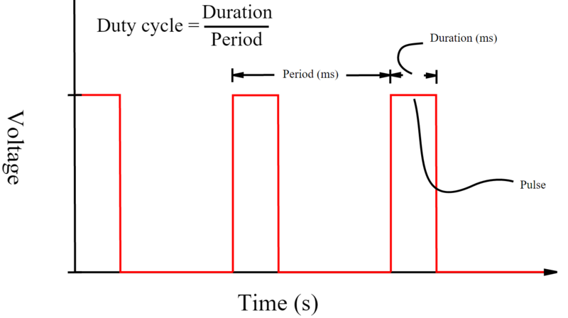
Here is the diagram shows the output of the PWM. PWM_FREQ variable from the previous sample code can control the period and p variable can control the duration.
For a drone, a shorter period can have better performance, but the range of the controlling will be smaller if we decrease the period. For example, my system is using 500 MHz PWM and my control rage will be about 53% to 100% because the motor will start to rotate at 53%. However, if we change the frequency, the motor will start to rotate at 90%, so the the control rage will be 90% to 100%. Therefor, we have to find the balance of the performance and the control rage.
How could decide the pwm period? Here are some rule we have to follow.
1.
The picture of the SJdrone

