Difference between revisions of "F14: Team3-Self Driving Car - Optimus Prime"
Proj user22 (talk | contribs) (→Geographical Team Schedule) |
Proj user22 (talk | contribs) (→Geographical Team Schedule) |
||
| Line 1,005: | Line 1,005: | ||
| | | | ||
Finished | Finished | ||
| + | | | ||
10/16/2014 | 10/16/2014 | ||
|- | |- | ||
Revision as of 11:00, 22 December 2014
Contents
Grading Criteria
- How well is Software & Hardware Design described?
- How well can this report be used to reproduce this project?
- Code Quality
- Overall Report Quality:
- Software Block Diagrams
- Hardware Block Diagrams
- Schematic Quality
- Quality of technical challenges and solutions adopted.
Optimus Prime: The Self-driving Car
This project report is about designing and building a self governing car, capable of sensing its environment and navigating without human input. The car senses its surroundings and is capable of updating their maps based on sensory input, allowing the vehicle to keep track of its position.
Abstract
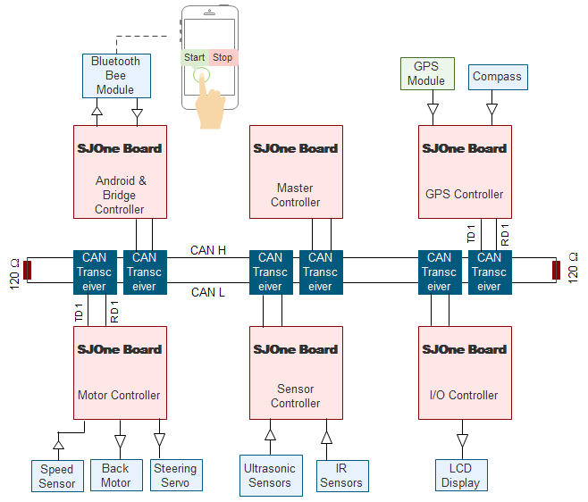
This project is about developing a self driven car. It consists of 6 controllers - Master, Motor, Sensor, GPS, Communication Bridge and I/O, which communicate with each other over the CAN bus as shown below. Each controller sends out the information over the CAN bus in the form of messages. Every controller receives only the required messages and performs the necessary task. The path navigation is achieved by the GPS. Thus the controllers do the task of a driver and navigate the path by avoiding the obstacles.
Parts List & Cost
| Item# | Part Desciption | Vendor | Part Number | Qty | Cost |
|---|---|---|---|---|---|
| 1 | RC Car | Amazon.com | Traxxas 37076 Rustler VXL | 1 | $380.57 |
| 2 | RC Car Battery | Amazon.com | Traxxas 2926 NiMH 8.4V Hump 3000mAh TRA Connector | 2 | $67.38 |
| 3 | CAN Transceiver | Texas Instrument | SN65HVD232D | 15 | $75.00 |
| 4 | Assembly Components | Amazon.com, Anchor & HSC | PCBs, Mechnical & Electical Components | NA | $110.80 |
| 5 | Power Supply | Pololu.com | 6V Battery, 5V Regulator | 1 | $34.85 |
| 6 | Sonar sensor | Maxbotix | LV-MaxSonar-EZ1 MB1010 | 3 | $99.55 |
| 7 | Sonar sensor | Given by Preet | LV-MaxSonar-EZ1 MB1010 | 1 | Free |
| 8 | Compass Module | Given by Preet | HoneyWell: HMC 6352 | 1 | Free |
| 9 | LCD Display | New Haven | NHD-0216B3Z-FL-GBW-V3-ND | 1 | $$$.$$ |
| 10 | Battery Status | Amazon.com | Dc 4.0-30v LED Digital Display Voltage Meter | 1 | $6.91 |
| 11 | Bluetooth Bee | Amazon.com | B005GI4HFA | 1 | $23.00 |
| Total Cost | $$$.$$ |
Introduction
CAN Bus: A brief introduction
TODO
The Six Controllers
- Master Controller
- Motor Controller
- Sensor Controller
- Geographical Controller
- Android & Communication Bridge Controller
- I/O Unit Controller
Design & Implementation
Controller Communication Table
| Controller ID | Controller Type |
| 0x01 | Master Controller |
| 0x02 | Motor Controller |
| 0x03 | Sensor Controller |
| 0x04 | Geographical Controller |
| 0x05 | IO Controller |
| 0x06 | Bridge Controller |
| Message Number | Purpose / Data layout |
| 0x101 | Get version and boot info |
| 0x102 | Get general info |
| 0x103 | Synchronize (set) time:
byte [0-3] : System time |
| 0x201 |
byte [0-3] : Version Info byte [4-7] : boot timestamp |
| 0x202 |
byte [0-3] : Current time byte [4] : CPU usage % |
| Byte 0 | Effect |
| 0 | Off |
| 1 | 1Hz |
| 5 | 5Hz |
| 10 | 10Hz |
| 20 | 20Hz |
| 50 | 50Hz |
| Any other value | Invalid date rate |
Master Controller
Group Members
Bhargava Leepeng Chandra
Shashank Tupkar
Preeti Benake
Master Controller Team Schedule
| Week No. | Start Date | Planned End Date | Task | Status | Actual End Date |
|---|---|---|---|---|---|
| 1 | 9/30/2014 | 10/7/2014 |
* Implement Basic CAN Hardware to communicate between 2 Controllers |
|
10/7/2014 |
| 2 | 10/7/2014 | 10/14/2014 |
* Design CAN Acceptance Filter among different Controllers * Define and Implement CAN Frame structure for proper communication establishment |
|
10/11/2014 |
| 3 | 10/14/2014 | 10/21/2014 |
* Develop Inter-Controller Communication over CAN * Test point-to-point and Broadcast message transmission * Implement a Counter to count and display number of messages |
|
10/19/2014 |
| 4 | 10/21/2014 | 10/28/2014 |
* Layout blueprint for Controller and Module positioning * Assemble the RC Car with all the controllers and Modules * Define the Message List by working with other teams * Start working on CAN Periodic message structure |
|
10/28/2014 |
| 5 | 10/28/2014 | 11/04/2014 |
* Complete CAN Periodic message structure to transmit Broadcast messages over CAN and establish controlled communication among different controllers * Implement Start condition detection and Fetch boot status from all controllers and display the status of each controller |
|
11/03/2014 |
| 6 | 11/04/2014 | 11/11/2014 |
* Design 'Kill Switch' in co-ordination with Motor Controller team and Bridge Controller team * Develop a 'CAN Bus Crash' detection and reset CAN Bus methodology * Design Automatic Head Light turn ON/OFF functionality by working with Sensors Controller team |
|
11/11/2014 |
| 7 | 11/11/2014 | 11/18/2014 |
* Implement File Log saving to SD Card at periodic intervals * Work on Restoring to last known Status if the system crashes while running * Develop Detection technique if controllers are reaching 'Error State' |
|
11/18/2014 |
| 8 | 11/18/2014 | 11/25/2014 |
* Project Integration and testing Basic Self_Drive Capability of the Car * Check the Functionality and behavior of all controllers in all the known contexts * Perform modifications (if any) to eliminate any bugs to make the car work seamlessly * Final Integration of car and testing there after |
|
11/26/2014 |
| 9 | 11/25/2014 | 12/02/2014 |
* Final Integration and testing Self_Drive Capability of the Car |
|
--/--/---- |
Hardware Design
Include Block Diagram
Hardware Interface
Include Pin Diagram, Pin Connectivity Table
| Description | Your Device Port | SJOne Development Board Port | Commands | Note |
|---|---|---|---|---|
| Supply Voltage | ||||
| Ground | GND | |||
| CAN Transceiver | Pin no. 1 Driver Input
Pin no. 4 Receiver Output |
P0.1 CAN TD1
P0.0 CAN RD1 |
Software Design
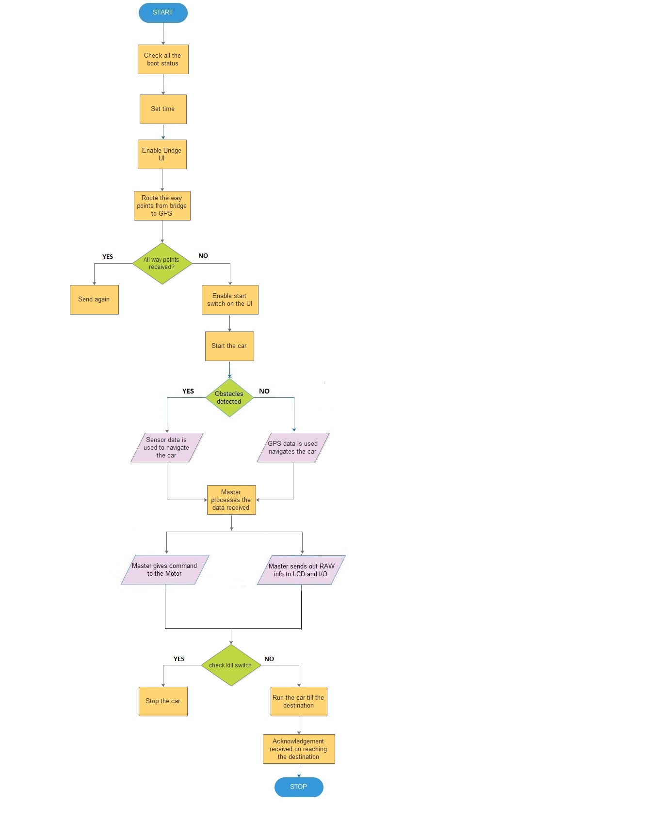
The software implementation of the master controller is explained by the flowchart.
Implementation
| Message Number | Purpose | Data Byte Pattern | |
| 0x101 | Ask for Boot and Version Info. of all Controllers |
Byte[0]: Send a '1' |
|
| 0x103 | Sync. Master System Time on all Controllers |
Byte[0-3]: System Time [HH:MM:SS] |
|
| 0x201 | Master Gets Status Update from all controllers |
Byte[0]: Boot Status Byte[1]: Version Info. |
|
| 0x203 | Master Gets current Time from all Controllers |
Byte[0-3]: Time in [HH:MM:SS] |
|
| 0x301 | Master Enable Main UI in Android |
Byte[0]: Send a '1' |
|
| 0x302 | Master set GPS Destination on Geo Controller |
Byte[0-3]: Latitude Value Byte[4-7]: Longitude Value |
|
| 0x303 | Master set Longitude Way-Points on Geo |
bytes [0-1] : Total Way-Points count bytes [2-3] : Way-Point index bytes [4-7] : Longitude(float) |
|
| 0x304 | Master set Latitude Way-Points on Geo |
bytes [0-1] : Total Way-Points count bytes [2-3] : Way-Point index bytes [4-7] : Latitude(float) |
|
| 0x305 | Master Send GPS FIX Ack to Bridge |
Byte[0]: Send a value '1' |
|
| 0x306 | Master Send Dest. Reached Ack to Bridge |
Byte[0]: Send a Value '1' |
|
| 0x500 | Display Boot and Version Info. on LCD |
Byte[0]: Boot Status Response Byte[1]: Version Info. |
|
| 0x501 | Display Controllers Time on LCD |
Byte[0-3]: Time in [HH:MM:SS] |
|
| 0x502 | Display Destination Has Reached |
Byte[0]: Send a '1' |
|
| 0x503 | Master Set Speed and Direction of Motor |
Byte[0]: LEFT/RIGHT (or) FRONT/BACK command |
|
| 0x504 | Display Speed of Motor on LCD |
Byte[0]: Speed Value |
|
| 0x505 | Display GPS and Compass values on LCD |
Byte[0-1]: New Degree to Head Byte[2-3]: Dist to Destination Byte[4-5]: Current Degree value |
|
| 0x506 | Display Sensor Values on LCD |
Byte [0]: Front sensor value in inches Byte [1]: Front Left sensor value in inches Byte [2]: Front Right sensor value in inches Byte [3]: Back sensor value in inches |
|
| 0x507 | Display Battery Status on LCD |
Byte[0]: Battery Status Value |
Testing and Technical Challenge
- Master Controller functions as the brain of car. The only challenge was integrating the master controller with the remaining five controllers.
- Describe how you tested the Master Controller and problems faced while integrating it with all the other controllers.
Mention the Issues you faced and also the solutions you'll used to overcome the problem.
Motor Controller
Group Members
Shashank Tupkar
Naghma Anwar
Shiva Moballegh
Motor Controller Team Schedule
| Week No. | Start Date | Planned End Date | Task | Status | Actual End Date |
|---|---|---|---|---|---|
| 1 | 9/30/2014 | 10/7/2014 |
* Study SJOne board's motor controller concepts and PWM |
|
10/7/2014 |
| 2 | 10/7/2014 | 10/14/2014 |
* Open up RC Car's motor and servo connections * Study the Electronic Speed Control's functions |
|
10/11/2014 |
| 3 | 10/14/2014 | 10/21/2014 |
* Define the duty cycles for proper motor and servo signals |
|
10/19/2014 |
| 4 | 10/21/2014 | 10/28/2014 |
* Add CAN frame structure to the motor functions * Test for communication between motors and sensors for prototype demo * Define the Message List by working with other teams |
|
11/04/2014 |
| 5 | 10/28/2014 | 11/04/2014 |
* Start working on CAN Periodic message structure * Start looking for speed sensors |
|
11/04/2014 |
| 6 | 11/04/2014 | 11/11/2014 |
* Attach speed sensors to the motor * Test CAN communication between motor controller and other controllers |
|
11/11/2014 |
| 7 | 11/11/2014 | 11/18/2014 |
* Work on speed sensors. Figure out the way to send sensor data to master controller. * Test for proper and accurate CAN communication |
|
11/18/2014 |
| 8 | 11/18/2014 | 11/25/2014 |
* Project Integration and testing basic self drive capability of the car * Check the functionality and behavior of the motor controller in all the known contexts * Perform modifications (if any) to eliminate any bugs to make the motor work seamlessly * Final Integration of car and testing there after |
|
--/--/---- |
Hardware Design
Parts and their functions
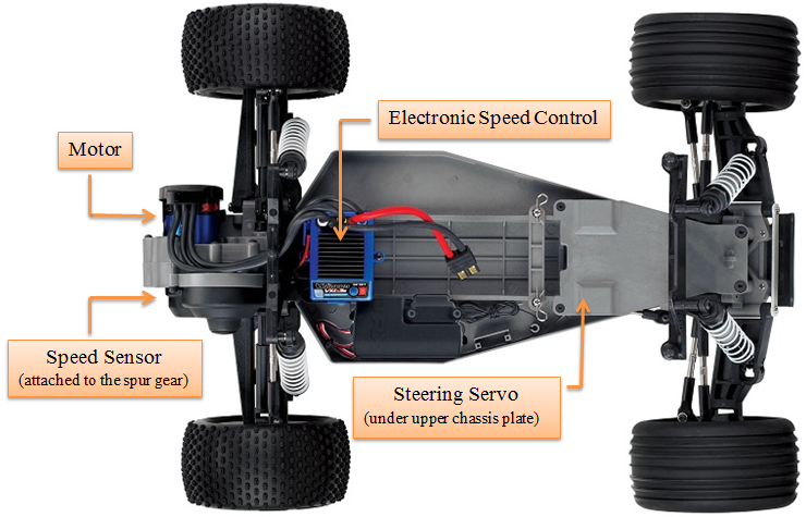
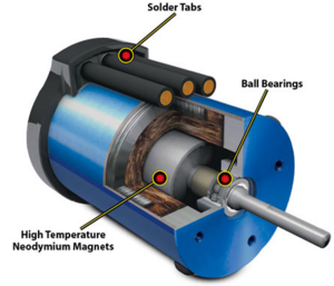
Motor : Our RC car came with Velineon 3500 Brushless Motor. One of the main drawbacks of brushless motor is that it requires a speed controller to change the field polarity. We can't just give power to the motor directly and expect it to go. We can almost consider the controller as an integral part of the motor itself.
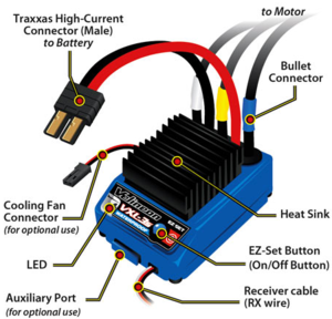
ESC : Electronic speed controller was the trickiest part to deal with, since it comes with a previously programmed microcontroller inside it. It needs callibration, for which you need to refer to the user manual. An electronic speed controller basically controls the power given to the motor. Our RC car came with VXL-3s ESC, which accepted 100 Hz PWM input signal whose duty cycle varied from 10% to 20%. When supplied with a 15% duty cycle at 100 Hz, the ESC responded by turning off the motor attached to its output.
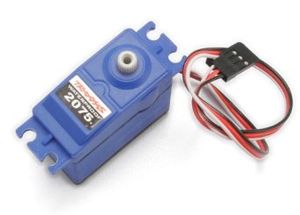
Steering Servo : Our RC car was equipped with a digital servo (Traxxas part #2075) for steering control. It does not require an ESC to operate. We can give PWM signal directly to the servo from the SJOne board. The servo accepted 100 Hz PWM input signal whose duty cycle varied from 10% to 20%, where 10% represents extreme right turn and 20% represents extreme left turn.Speed Sensor : To measure the RPM and speed of our car, we used the speed sensor provided by Traxxas Telemetry. This magnetic speed sensor worked on Hall effect. To learn more about Hall effect sensors, you can click on this wikipedia article. Since the sensor was provided by the same brand of our car, the installation was quick and easy. Here's a reference video on how to attach magnetic speed sensor to the RC car.
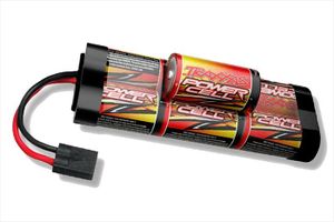
Battery : We used 7 Cell NiMH (Nickel-Metal Hydride) battery pack for our car but would recommend others to use Lipo (Lithium Polymer) batteries instead. NiMH batteries tend to discharge very quickly. Also we realized later that since this car was made for racing purpose, its speed was too fast for our project. We reduced the voltage by removing 2 cells from the 7 cell battery pack. So, go for the 5 cell battery pack instead. A Traxxas EZ-Peak Charger would help a lot while doing testing.
Hardware Interface
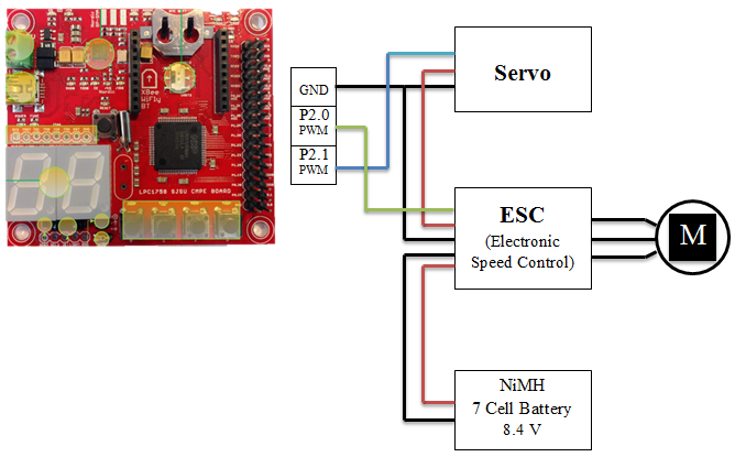
Motor and Servo Interface
Speed Sensor Interface
| Description | Your Device Port | SJOne Development Board Port | Commands | Note |
|---|---|---|---|---|
| Supply Voltage | 6V from NiMH battery | N/A | ||
| Ground | GND (Black Wire) | GND | ||
| ESC |
Control (White Wire) |
P2.0 PWM |
PWM motor(PWM::pwm1, 101); motor.set(14.5); |
Sets PWM signal of 101 Hz Sets duty cycle of 14.5% for forward movement |
| Servo |
Control (White Wire) |
P2.1 PWM |
PWM servo(PWM::pwm2, 101); servo.set(15); |
Sets PWM signal of 101 Hz Sets duty cycle of 15% for no turn |
| CAN Transceiver |
Pin no. 1 Driver Input Pin no. 4 Receiver Output |
P0.1 CAN TD1 P0.0 CAN RD1 |
TI CAN Transceiver SN65HVD232D Pin 7 - CAN H & Pin 6 - CAN L |
Software Design
Include Flow Chart
Implementation
Include Communication Table
| Message Number | Purpose | Data layout |
| 0x508 | Speed Sensor Data |
byte [0] : Speed sensor value in rpm |
| 0x509 | Vehicle Direction/Movement Data |
byte [0] : Movement Control
     0x1 : Forward
     0x2 : Reverse
     0x3 : Stop
byte [1] : Steering Control
     0x1 : Left
     0x2 : Right
     0x3 : Straight
|
Testing and Technical Challenge
- Motor Controller
- Describe how you tested the motors. Explain the speed control methods used and difficulties you faced during calibration.
Mention the Issues you faced and also the solutions you'll used to overcome the problem.
Sensor Controller
Group Members
Deepak Yadav
Vinod Pangul
Sensor Team Schedule
| Sl.No | Start Date | End Date | Task | Status | Actual Completion Date |
|---|---|---|---|---|---|
| 1 | 10/6/2014 | 10/18/2014 | Order Ultra Sonic Sensors | Completed [Got two sensors (front and back), 2 more (front right & left) to order ->Completed.] | 10/19/2014 |
| 2 | 10/9/2014 | 10/9/2014 | Sensor Data Sheet review with the team | Completed | 10/9/2014 |
| 3 | 10/9/2014 | 10/16/2104 | Sensor code development | Completed (Implementing filter (HW/SW) to get more accurate data ->(Done). Add logic to get the rest of the three sensor(front right/left and back data)->(Done) (Note: Delayed due to the implementation of CAN structure and calibration of IR sensor) | 10/21/2014 |
| 4 | 10/22/2014 | 10/25/2014 | Sensor software testing | Completed | 10/25/2014 |
| 5 | 10/25/2014 | 10/28/2014 | Sensor real time testing | Completed | 10/28/2014 |
| 6 | 10/13/2014 | 10/15/2014 | Light sensor code Development | Completed | 10/14/2014 |
| 7 | 10/13/2014 | 10/15/2014 | Accelerometer sensor code Development to detect tilt | Completed | 10/14/2014 |
| 8 | 10/15/2014 | 10/15/2014 | Light Sensor and Accelerometer Testing | Completed | 10/15/2014 |
| 11 | 11/03/2014 | 11/04/2014 | Common Communication SW code implementation and testing | Completed | 11/04/2014 |
| 11 | 11/04/2014 | 11/09/2014 | Complete Hardware testing-1 | Completed | 11/09/2014 |
| 12 | 11/10/2014 | 11/15/2014 | Complete Hardware testing-2 | Completed | 11/15/2014 |
Hardware Design
Include Block Diagram
Sensors : Sonar Sensors + Light and Accelerometer sensor
A) Sonar Sensor:
- The ultrasonic sensors are in air, non-contact object detection and ranging sensors that detect objects within an area.
- We are using 3 such sensors in front to get wide angle vision for the car.
- Ultrasonic sensors use high frequency sound to detect and localize objects in a variety of environments. Ultrasonic sensors measure the time of flight for sound
that has been transmitted to and reflected back from nearby objects. Based upon the time of flight, the sensor then outputs a range reading.
Hardware Interface
Include Pin Diagram, Pin Connectivity Table
| Description | Your Device Port | SJOne Development Board Port | Commands | Note |
|---|---|---|---|---|
| Supply Voltage | ||||
| Ground | GND | |||
| Sonar Sensor | ||||
| IR Sensor | ||||
| CAN Transceiver | Pin no. 1 Driver Input
Pin no. 4 Receiver Output |
P0.1 CAN TD1
P0.0 CAN RD1 |
Software Design
Include Flow Chart
Implementation
Include Communication Table
| Message Number | Purpose | Data layout |
| 0x510 | Front/Back Range Sensor Data |
byte [0] : Front sensor value in inches byte [1] : Front Left sensor value in inches byte [2] : Front Right sensor value in inches byte [3] : Back sensor value in inches |
| 0x511 | Accelerometer/Light/Battery Sensor Data |
byte [0] : X axis Value byte [1] : Y axis Value byte [2] : Z axis Value byte [3] : Light sensor value byte [4] : Battery status value |
Testing and Technical Challenge
- Front and Back Sensors Controller
- Describe how you tested the Sensors and calibration of the sensors
Mention the Issues you faced and also the solutions you'll used to overcome the problem.
Geographical Controller
Group Members
Bhushan Gopala Reddy
Ryan Marlin
Rishikesh Nagare
Geographical Team Schedule
| Sl.No | Start Date | End Date | Task | Status | Actual Completion Date |
|---|---|---|---|---|---|
| 1 |
10/4/2014 |
10/13/2014 |
Research and Order GPS module |
Received GPS module |
10/7/2014 |
| 2 |
10/7/2014 |
10/18/2014 |
Interface GPS module with LPC1758 |
Finished |
10/17/14 |
| 3 |
10/14/2014 |
10/18/2014 |
Receive Compass module from Preet |
Received |
10/9/2014 |
| 4 |
10/18/2014 |
11/4/2014 |
Parse GPS data and setup constructs to send appropriate data |
Finished |
11/1/2014 |
| 5 |
10/14/2014 |
10/18/2014 |
Interface the Compass Module |
Finished |
10/16/2014 |
| 6 |
10/25/2014 |
11/4/2014 |
Calibration of Compass |
Finished |
11/1/2014 |
| 7 |
11/4/2014 |
11/11/2014 |
Integrate GPS and Compass data |
Finished |
11/4/2014 |
| 8 |
10/25/2014 |
11/30/2014 |
Testing and mapping of GPS co-ordinates |
Finished |
11/20/2014 |
| 9 |
11/18/2014 |
12/18/2014 |
Final integration and testing |
Finished |
12/15/2014 |
Hardware Design
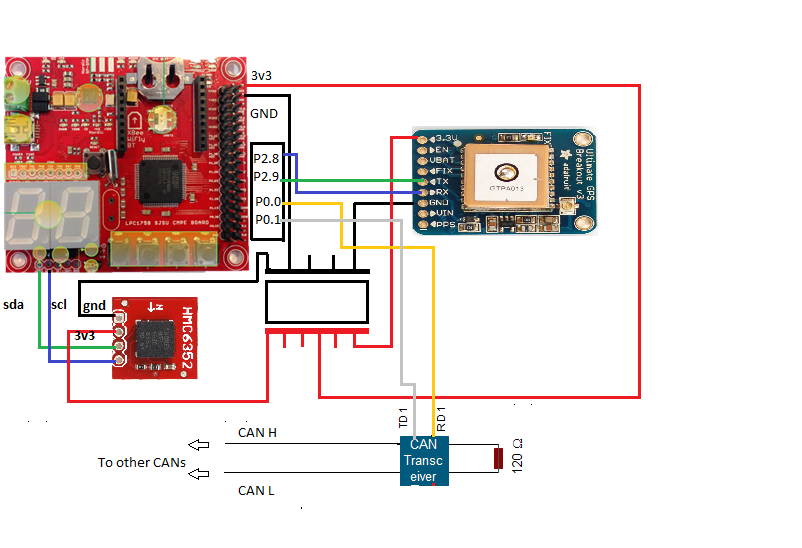
Hardware Interface
| Description | Your Device Port | SJOne Development Board Port | Commands | Note |
|---|---|---|---|---|
| Supply Voltage | Vcc | 3v3 | ||
| Ground | GND | GND | ||
| GPS Module |
Channel 1 -> Rx, Channel 2 -> Tx |
Channel 1-> Tx P2.8, Channel 2-> Rx P2.9 |
||
| Compass |
SCL SDA |
SCL2 -> P0.11 SDA2 -> P0.10 |
||
| CAN Transceiver |
Pin no. 1 Driver Input Pin no. 4 Receiver Output |
P0.1 CAN TD1 P0.0 CAN RD1 |
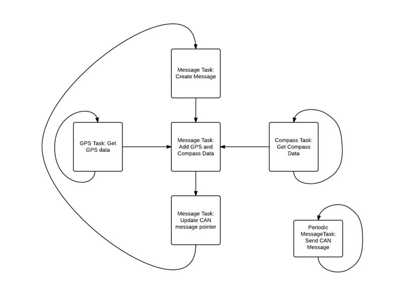
Software Design
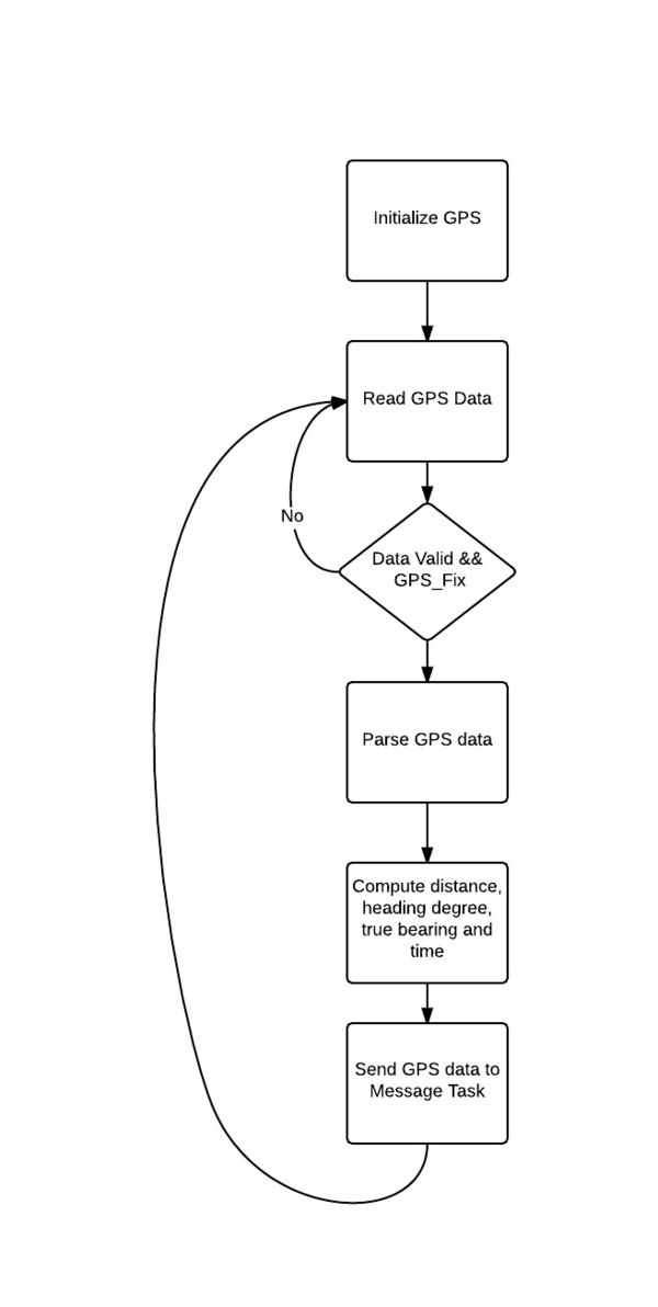
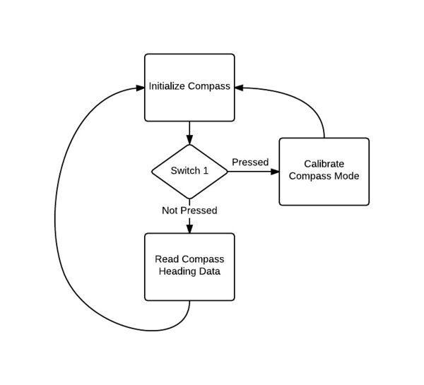
The figure above shows a top level view of the geographical team's software flow. The main message task, shown in the middle, is responsible for handling and updating the CAN message pointer. The CAN message pointer is read and handled in a separate periodic task that runs and sends messages across the CAN bus at frequencies of 1, 5, 10 or 20 Hz.
The GPS and compass tasks, shown on the left and right respectively, collect their respective data and send that data to the message task. The message task will grab this data and stuff the CAN message variable to be sent to the Master module.
GPS
NMEA (National Marine Electronics Association)
- NMEA consists of sentences, the first word of which, called a data type, defines the interpretation of the rest of the sentence.
- Each Data type would have its own unique interpretation and is defined in the NMEA standard.
- In our project we are using RMC (Recommended Minimum GPS data).Below is an example of RMC data.
$GPRMC,123519,A,4807.038,N,01131.000,E,022.4,084.4,230394,003.1,W*6A
Where:
    RMC          Recommended Minimum sentence C
    123519       Fix taken at 12:35:19 UTC
    A            Status A=active or V=Void.
    4807.038,N   Latitude 48 deg 07.038' N
    01131.000,E  Longitude 11 deg 31.000' E
    022.4        Speed over the ground in knots
    084.4        Track angle in degrees True
    230394       Date - 23rd of March 1994
    003.1,W      Magnetic Variation
    *6A          The checksum data, always begins with *
Connection and Software Flow GPS:
SJone board and GPS module is connected using UART. At boot-up GPS tries to get fix for all possible satellites to get proper GPS values.
Compass
The Compass works over the I2C bus interface. Based on the datasheet, the compass will send data when it receives a 'A' command.
Implementation
Include Communication Table
| Message Number | Purpose | Data layout |
| 0x518 | Send GPS Data to Master |
byte [0] : New Degree byte [1] : Distance byte [2] : Current Degree |
| 0x519 | Send GPS FIX ACK to Master |
byte[0]: Send a '1' |
| 0x52A | Send Destination Reached ACK to master |
byte[0]: Send a '1' |
Testing and Technical Challenge
- Geographical Controller
- GPS
- GPS data was relatively straightforward to receive, however we ran into quite a few issues trying to parse the data.
- Often times we would read the UART data in the middle of the buffer being changes to the next data point, for example, the reading would look like this:
- $GPRMC,123519,A,4807.038,N,01131.000,E,022.4,084.4$GPRMC,123519,A,4807.038
- Instead of the normal data point: $GPRMC,123519,A,4807.038,N,01131.000,E,022.4,084.4,230394,003.1,W*6A
- By checking the Checksum at the end of the string, *6A, we were able to determine the number of characters that were supposed to be in the string and exclude any strings that did not have the correct number of characters.
- Compass
- GPS
Describe how you tested the Compass and explain how did you manage to achieve the maximum accuracy. Mention the Issues you faced and also the solutions you'll used to overcome the problem.
Android & Communication Bridge Controller
Group Members
Chia-Pin Tseng (Ben)
Johnny Yam
Kevin Beadle
Communication Bridge & Android Team Schedule
| Sl.No | Start Date | Planned End Date | Task | Status | Actual End Date |
|---|---|---|---|---|---|
| 1 | 9/30/2014 | 9/30/2014 | Obtain Bluetooth Module (already had one) | Done | 9/30/2014 |
| 2 | 9/30/2014 | 10/14/2014 | Develop Basic Android App with Bluetooth Sensor Communication | Done | 10/7/2014 |
| 3 | 10/11/2014 | 10/14/2014 | Interface Bluetooth Module with SJSU Dev Board | Done | 10/11/2014 |
| 4 | 10/12/2014 | 10/19/2014 | Be able to send bi-directional arbitrary messages between Android App and Dev Board via Bluetooth | Done | 10/14/2014 |
| 5 | 10/14/2014 | 11/21/2014 | Subscribe to all CAN messages and dump all of them via Bluetooth to Android App or web interface | Done | 11/24/2014 |
| 6 | 10/14/2014 | 11/21/2014 | Ajax & Websocket server remote structure | Done | 11/01/2014 |
| 7 | 10/14/2014 | 11/21/2014 | Be able to input GPS coordinates through either (or both) Android App and web interface and send through Bluetooth then CAN bus | Done | 11/24/2014 |
| 8 | 10/21/2014 | 11/24/2014 | Android App and webpage GUI enhancements (Google Maps, Google Drive) | Done | 11/24/2014 |
| 9 | 10/21/2014 | 11/30/2014 | Data visualization (status, compass, speed, location,....) | Done | 11/30/2014 |
Hardware Design
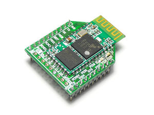
- In order to facilitate wireless communication between the SJSU One Board and a Android device, a Bluetooth Bee module is used. This module was chosen because it can connect and mount directly onto the SJSU One Board's XBee breakout socket.
- The Bluetooth Bee is a Serial Profile Port (SPP) Bluetooth interface that connects with the SJSU development board's UART3.
Hardware Interface
The relevant pin connectivity table between the Bluetooth Bee module and the SJSU One Development Board is shown below:
| Description | Bluetooth Bee Port | SJSU Development Board Port | CAN Transceiver |
| 3.3V Supply Voltage | 3V3 | 3V3 | 3V2 |
| Ground | GND | GND | GND |
| UART Channel 1 | TX | RX | |
| UART Channel 2 | RX | TX | |
| CAN TXD | CAN TD1 | TXD | |
| CAN RXD | CAN RD1 | RXD |
The Bluetooth Bee Module interfaces with an Android device through Bluetooth. In addition, various commands and data are then sent and received to and from the CAN bus through the Bluetooth Module to the Android device.
Software Design
- The bridge controller and Android APP work as routers
Bridge Controller
- Bridge controller translates CAN bus data into plain text and send it to android platform
- The Bridge controller is comprised of the SJSU Development Board with the Bluetooth Bee Module.
- The Bluetooth Bee Module can be configured by writing to UART3 specific commands as specified in the Bluetooth Bee Seeedstudio Wiki.
- The Bluetooth Bee Module was configured as SLAVE MODE via the command: \r\n+STWMOD=0\r\n (The Android device will act as the Bluetooth Master)
- The Bluetooth device name was set to "Yam_BluetoothBee" using the command: \r\n+STNA=Yam_BluetoothBee\r\n
- Allowing other devices to connect to the Bluetooth Module was enabled using the command: \r\n+STOAUT=1\r\n
- Finally the Bluetooth Bee Module started broadcasting/inquiring to connect to another device using the command: \r\n+INQ=1\r\n
- There are many other commands, such as to change the default pincode value, but they were not used for this project.
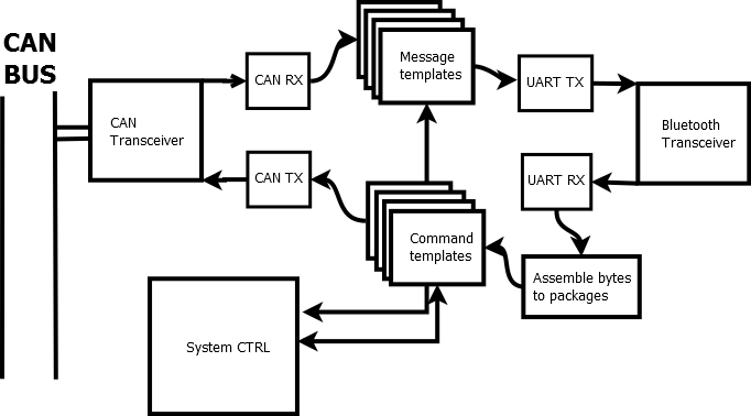
The architecture for our bridge controller is to interconvert the data between Bluetooth message and CAN bus message. Bluetooth message uses simple plaintext to transfer data. However, before we can deal with the string data, to collect and assemble several bytes into a package is needed, because UART is byte based data transmission. I use a byte 0x13(which is ‘\r’ in C code) at the end byte.The bluetooth sender must send 0x13 in the end of every text message. This process is achieved by BluBeeTask_BT2CAN class. CAN bus message uses 29bits as message ID and 8bytes data length as a single package to communicate with the master controller. There are two main classes for the controller. BluBeeTask_BT2CAN and BluBeeTask_CAN2BT.
- BluBeeTask_BT2CAN
BluBeeTask_BT2CAN is responsible for receiving the data which comes from bluetooth(via UART).We can setup multiple message filters to receive and process certain message data.
Filter setting format.
    blutoothReceiverTask->addCMD(
    BluBeeTask_BT2CAN::CMDProp::gen((char* cmd,
               bool (*func)(BluBeeTask_BT2CAN *, char* CMDStr)));
For example, there is a message format “Speed” to control the speed of the automatic car. We can simply apply a filter as below
    blutoothReceiverTask->addCMD(
    BluBeeTask_BT2CAN::CMDProp::gen("Speed", SpeedCMD));
then, we have a callback function “SpeedCMD” that can only receive speed setting messages.(For instance there is a message “Speed23” was sent by Android)
    bool SpeedCMD(BluBeeTask_BT2CAN *sender, char* CMDStr)//CMDStr will be “23”
    {
        int speed = 0;
        CMDStr=parseInt(CMDStr,&speed);//parse string “23” into integer 23
        can_msg_t msg = { 0 };//CAN message
        msg.msg_id = make_id(cid_master_controller, CAN_TX_CAR_SPEED_MSG_ID);
        //Set the ID to send to master controller with speed message ID
        *(int *) &(msg.data.bytes[0]) = speed;//First byte is the speed 23
        return sender->Send2CAN(msg);//Send message via CAN bus
    }
You can see the call back function SpeedCMD is doing a very simple string processing, then, send it to the master controller via CAN bus.
- BluBeeTask_CAN2BT
What BluBeeTask_CAN2BT doing is actually very similar to BluBeeTask_BT2CAN. First, you need to apply CAN message filters and set the corresponding callback functions.
Filter setting format.
    CANReceiverTask->addMsgTamp(
           BluBeeTask_CAN2BT::MsgProp::gen(
                 (controller_id_t MsgIdTmp, controller_id_t Mask,
           bool (*func)(BluBeeTask_CAN2BT *, can_msg_t Msg)));
controller_id_t is the set of information of CAN message ID including source, destination, and message number. To setup a controller_id_t variable you can simply use a function make_id.
controller_id_t ID= make_id(destination,source,message Number);
MsgIdTmp is the message ID that you wanna receive. Bit 1 in mask means that certain bit you need to compare between MsgIdTmp and received message ID.
|
received message ID [00,12,07] MsgIdTmp [20,12,31] Mask [00,FF,00] Success First mask data 00 means ignore the first data difference between received message ID and MsgIdTmp(ignore 00!=20). Second mask data FF means you need to compare the second data. In this case both are 12, therefore, it passes the comparison Third mask data is 00 (ignore 07!=20). |
received message ID [00,12,07] MsgIdTmp [20,12,31] Mask [00,FF,FF] Failed Third mask data is FF, so we need to compare 07 and 31. Apparently, 07 is not equal to 31, so the comparison is failed. |
For example, there is a compass message comes from master. We can simply apply a filter as below
   can2btptr->addMsgTamp(
           BluBeeTask_CAN2BT::MsgProp::gen(
                   make_id(0, cid_master_controller,
                           CAN_RX_DA_COMPASSSTATUS_MSG_ID), //Message ID templete
                   make_id(0,0xFFF,0xFFF)//Mask means don’t compare source section
                   , compassMSG));//Set Callback function compassMSG
We have a callback function “compassMSG” that can only receive compass messages and whichmessage was come from master controller. Since bridge controller receive this information, so we don’t need to compare destination.
 bool compassMSG(BluBeeTask_CAN2BT *canbt, can_msg_t Msg)
 {
     sprintf(STRBUFF, "geo::%d,%d,%d,%d\r", (int16_t) Msg.data.words[0],
           (int16_t) Msg.data.words[1], (int16_t) Msg.data.words[2],
           (int16_t) Msg.data.words[3]);
     //convert those data into a string
     //notice the end of the string is ‘\r’, which is needed
     canbt->Send2BT(STRBUFF);// send to UART(Bluetooth)
     return true;
 }
Android Controller
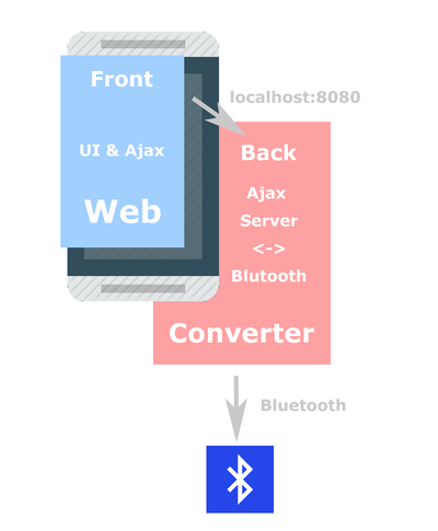
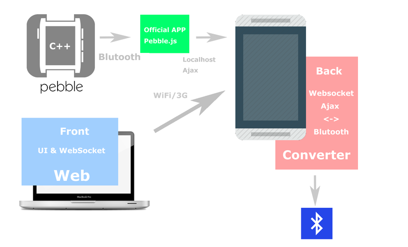
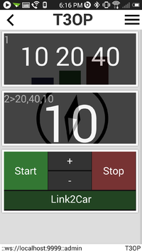
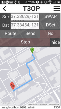
- Android platform receives the text data from bridge controller, then, transmit the data through ajax or websocket
- External controller could be any TCP accessible device (simple pebble watch program (20 lines) are used to control start and stop)
- One administrator(control and receive), multiple observers(only receive)
- Number of way points and routing is dynamically determined and done using the Google Maps API
Implementation
| Message Number | Purpose | Data layout |
| 0x528 | Set Car Speed (Kill Switch) - temporary allow for other non-zero value for demo | byte[0] - speed value |
| 0x529 | Destination GPS location |
bytes [0-3] : latitude (float) bytes [4-7] : longitude (float) |
| 0x52A | Turn to degree |
bytes [0-3] : degree(float) |
| 0x52B | Way points longitude |
bytes [0-1] :total waypoints count bytes [2-3] :waypoint index bytes [4-7] : longitude(float) |
| 0x52C | Way points latitude |
bytes [0-1] :total waypoints count bytes [2-3] :waypoint index bytes [4-7] : latitude(float) |
| 0x52D | remote status (ie. Android connection status) |
bytes [0]=> 0:disconnected(passive send) 1:on disconnect(active) 2:connected(passive) 3:on connect(active) 0xFF:error(active/passive) |
Testing and Technical Challenge
TESTs
- 100000 message(20bytes per message) Bluetooth transmission between board and android under 200fps with range <5m
- 100% success
ISSUE
- 3G network server could not be access(3G network is used for long range communication)
- might use google sheet or external server to communicate
I/O Unit Controller
Group Members
Shreeram Gopalakrishnan
Sreeharsha Paturu Gangadhara
IO Team Schedule
| Sl.No | Start Date | End Date | Task | Status | Actual Completion Date |
|---|---|---|---|---|---|
| 1 | 10/7/2014 | 10/13/2014 | Research and Order LCD Display | Ordered LCD Display | 10/13/2014 |
| 2 | 10/14/2014 | 10/21/2014 | Interfacing LCD Display with LPC1758 | Completed | 10/21/2014 |
| 3 | 10/21/2014 | 10/28/2014 | Implementing CAN structure with LCD tasks. | Completed | 11/30/2014 |
| 4 | 10/28/2014 | 11/04/2014 | Subscribe data from motor, sensor and GPS controller,display it on LCD. | Ongoing | |
| 5 | 11/04/2014 | 11/11/2014 | Setup hardware and write code for START, STOP and Headlight buttons. | TBD | |
| 6 | 11/11/2014 | 11/18/2014 | Testing and mounting hardware on car. | TBD | |
| 7 | 11/18/2014 | 11/25/2014 | Final Testing | TBD |
Hardware Design
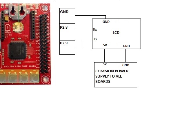
- The IO Control Unit manages the LCD Display, switch to start and stop the car
- It receives CAN data from the Master controller and accordingly processes to display on the LCD through UART
- The 7 segment LED displays the CPU usage
LCD Display
- The LCD Display is placed on the rear side of our RC Car
- It displays the sensor and GPS values in real time.
Hardware Interface
| Description | Your Device Port | SJOne Development Board Port | Commands | Note |
|---|---|---|---|---|
| Supply Voltage | 5V supply |
Receives 5V supply that is used to power up all the boards | ||
| Ground | GND | GND | ||
| LCD Display |
Rx pin Tx pin |
Rx ---> TXD2 (Port 2.8) Tx ---> RXD2 (Port 2.9) |
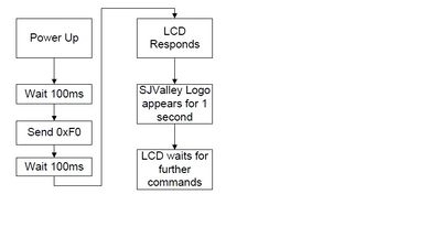
 u2.putline("F0")
 u2.putline("$CLR_SCR")
 u2.putline("$GOTO:3:0")
|
Initialization command for LCD Clears the screen Point the cursor to line number 0 and character number 3 |
| CAN Transceiver |
Pin no. 1 Driver Input Pin no. 4 Receiver Output |
P0.1 CAN TD1 P0.0 CAN RD1 |
Software Design
Implementation
| Message Number | Purpose | Data layout |
| 0x102 | Send boot status and version info | bytes [0-2] : Status and version info |
| 0x505 | Display GPS and compass values |
Byte[0-1]: New Degree to Head Byte[2-3]: Dist to Destination Byte[4-5]: Current Degree value |
| 0x506 | Display Sensor Values |
Byte [0]: Front sensor value in inches Byte [1]: Front Left sensor value in inches Byte [2]: Front Right sensor value in inches Byte [3]: Back sensor value in inches Byte [4]: Speed value |
Testing and Technical Challenge
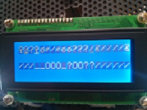
->Junk values being printed:
- Although this error was not a show stopper, LCD printed junk values whenever it was on and any of the boards were programmed.
- So, the only solution was to never program the board (connect the board to laptop) when LCD is on.
->Coding improvement
- In the code, initially, the GPS, Sensor values were being printed in one line in the code. So, either the values were overwritten or there was shifting of those values. This was a synchronization issue.
- Resolved it by, clearing each line in the LCD before printing it and used individual line in the code to print the values.
Conclusion
Project Video
Project Source Code
References
Acknowledgement
References Used
http://www.ti.com/product/sn65hvd232
http://www.socialledge.com/sjsu/index.php?title=Self-driving_Car
http://www.nxp.com/documents/user_manual/UM10360.pdf
http://www.socialledge.com/sjsu/images/d/de/2012SJOneBoardSchematic.pdf
http://www.maxbotix.com/documents/MB1010_Datasheet.pdf
http://www.sharpsma.com/webfm_send/1208
https://www.sparkfun.com/datasheets/Components/HMC6352.pdf
http://www.seeedstudio.com/wiki/Bluetooth_Bee
http://www.adafruit.com/product/746
=== Appendix ===
