F13: Garage Parking Assistant
Contents
Grading Criteria
- How well is Software & Hardware Design described?
- How well can this report be used to reproduce this project?
- Code Quality
- Overall Report Quality:
- Software Block Diagrams
- Hardware Block Diagrams
- Schematic Quality
- Quality of technical challenges and solutions adopted.
Garage Parking Assistant
Project by: Eric Maki & Kathryn Ng
Abstract
The purpose of this project is to build a multifunctional parking assistant. The parking assistant will simplify the driver’s task of parking a car in a garage. The parking assistant will automatically open the garage door as the vehicle approaches the garage. Once the vehicle is inside the garage, the parking assistant will notify the driver of the vehicle's position relative to a predetermined stop point. When the vehicle reaches the stop point, the parking assistant will alert the driver with audible and visual cues.
Objectives & Introduction
The project consists of two separate modules which communicate with each other wirelessly. One module is located in the garage while the other is located in the vehicle with the driver. Each module is designed around an SJOne board with ARM Cortex-M3 (LPC1758) microcontroller.
The garage module uses an ultrasonic rangefinder to measure the distance of an approaching vehicle. The distance will be displayed symbolically on an LED strip. The distance will be transmitted wireless using the onboard Nordic IC to the vehicle module. The vehicle module will open the garage door, using a dissected garage door opener. It will display the distance on a 7-segment LED display and sound an alarm when the vehicle reaches it's stopping point.
Team Members & Responsibilities
- Eric - Garage Module
- Measure approaching distance
- Transmit distance
- Display closing distance
- Display stop point
- Kathryn - Vehicle Module
- Receive approaching distance
- Open garage door
- Display closing distance
- Sound alarm
Schedule
| Week# | Date | Task | Status |
|---|---|---|---|
| 1 | 10/08/13 | Proposal due. Order parts. | Completed task on time. |
| 2 | 10/15/13 | All parts arrive. Write code to open garage door. | Completed task on time. |
| 3 | 10/22/13 | Establish board-to-board wireless connection | Completed task on time. |
| 4 | 10/29/13 | Start working on tasks listed on 11/5 and 11/12. | Completed task on time. |
| 5 | 11/05/13 | Garage microcontroller: Range finder. Vehicle microcontroller: LED display | Completed task on time. |
| 6 | 11/12/13 | Garage microcontroller: LED strip functional. Vehicle microcontroller: Piezo functional | Completed task on time. |
| 7 | 11/19/13 | Complete garage/vehicle module integration. Start system testing. | Completed task on time. |
| 8 | 11/26/13 | Complete system testing. Practice Demo. | Completed task on time. |
| 9 | 12/03/13 | Complete demonstration. | Completed task on time. |
| 10 | 12/07/13 | Complete report. | Completed task on time. |
Parts List & Cost
Give a simple list of the cost of your project broken down by components. Do not write long stories here.
| Qty | Part | Cost | Purchase from |
|---|---|---|---|
| 2 | SJSU Board with LPC1758 microcontroller | $75 | SJSU CmpE |
| 2 | Antennas | Provided by instructor | |
| 1 | Addressable RGB LED Light Strip | $29.95 | Adafruit.com |
| 1 | Ultrasonic Rangefinder | Provided by instructor ($25.95) | Sparkfun.com |
| 1 | N-Channel MOSFET | $0.95 | Sparkfun.com |
| 1 | Universal Garage Door Remote | $34.97 | Home Depot / Walmart |
| 1 | Piezo Buzzer | Provided by instructor | |
| 2 | Connectors for LED strip lights (JST plug and receptacle) | $1.50 | Adafruit.com |
Design & Implementation
The design section can go over your hardware and software design. Organize this section using sub-sections that go over your design and implementation.
Hardware Design
Discuss your hardware design here. Show detailed schematics, and the interface here.
Rangefinder
The garage module uses an ultrasonic rangefinder to detect the distance of the approaching vehicle. An ultrasonic rangefinder was chosen over other rangefinder types because it has the best balance of range (0 - 21ft) and resolution (1 inch) for our application. The ultrasonic rangefinder outputs an analog signal to represent the distance to the vehicle. The analog signal is connected to an ADC input on the microcontroller which translates the signal to a numeric value. The microcontroller uses this value to compute the distance in inches.
The garage module symbolically displays the distance of the approaching vehicle on an LED strip. The LED strip houses 32, individually addressable, tri-color LEDs. Each LED has a red, green, and blue component; which can be mixed to output any visible color. The LED strip contains built in LPD8806 LED drivers. The LED drivers are interfaced via a daisy-chain SPI bus. Note: This SPI bus uses only two signals: Clock and MOSI.
The module is designed toggle the color of the individual between green and red depending on the distance of the the approaching vehicle. As the vehicle approaches, the LED's will, one-by-one, turn from green to red. When the vehicle reaches its stop point, the entire LED strip will flash red on/off.
The modules will communicate with each other using the onboard Nordic chip. The garage module uses this interface to transmit the distance to the vehicle module.
One of the garage microcontroller's responsibilities is to determine the distance of the approaching vehicle. The garage microcontroller uses an ultrasonic rangefinder to accomplish this task. The ultrasonic rangefinder measures the distance to the closest object and outputs it as an analog signal to the microcontroller. The microcontroller uses the onboard ADC to convert the analog signal to data. The data is then used to compute the distance, in feet.
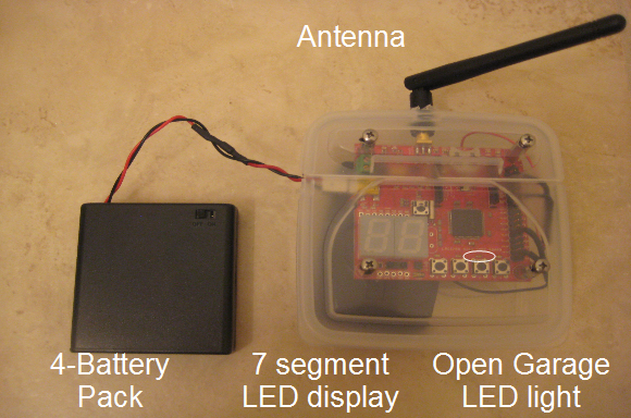
The photo below depicts a test of the ultrasonic rangefinder. The rangefinder is positioned to measure the distance to a nearby wall. The microcontroller is processing the analog distance signal and outputing the distance on it's onboard LED display. Note: The rangefinder and microcontroller are mounted in a temporary electronic enclosure for easy testing. The final design will be mounted in a compact plastic case.
LED Strip
A second responsibility of the garage microcontroller is to symbolically display the distance of the approaching vehicle on an LED strip. The LED's will incrementally turn on and change color as the vehicle approaches. When the vehicle reaches its final position the entire LED strip will flash red to indicate to the driver to stop.
The photo below depicts the LED light strip and the temporary enclosure mounted on the garage wall. The three left-most LEDs are turned on as a white color. The LED strip is connected to the enclosure using a ribbon cable. The enclosure is powered by an external 5V wall adapter.

Early stage testing of LED strip
Below is a close-up of the partially lit LED strip and the enclosure, both mounted on the wall.

Close-up of LED strip and temporary enclosure
Wireless
A third responsibility of the garage microcontroller is to wirelessly transmit the distance to the vehicle microcontroller. The garage microcontroller uses the onboard Nordic wireless radio in conjunction with an SMA antenna for maximum range.
*******************************
****Placeholder for picture****
*******************************
Close-up of SMA antenna
Garage Door Opener
The first task of the car microcontroller is to open the garage door by sending a GPIO signal to the remote controller when the car microcontroller receives data from garage microcontroller.
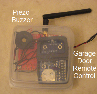
The photo below shows a rectangular garage door opener with the pushbutton cover removed connected to the car microcontroller.
LED Display - Car Side
The second task of the car microcontroller is to display the distance of the approaching vehicle on a 2-digit LED display on the car microcontroller. It requires the car microcontroller to receive distance data wirelessly from the garage microcontroller.
The photo below shows the 2-digit LED display on the car microcontroller.
Alarm
The third task of the car microcontroller is to sound an alarm to alert the driver that the car is too close to the car. At a certain distance, the piezo buzzer will make noise based upon the distance data sent wirelessly from the garage microcontroller. Tentatively, the buzzer will sound off about 2 feet from the wall.
The photo below shows the piezo buzzer connected to the car microcontroller.
Hardware Interface
In this section, you can describe how your hardware communicates, such as which BUSes used. You can discuss your driver implementation here, such that the Software Design section is isolated to talk about high level workings rather than inner working of your project.

Software Design
Show your software design. For example, if you are designing an MP3 Player, show the tasks that you are using, and what they are doing at a high level. Do not show the details of the code. For example, do not show exact code, but you may show psuedocode and fragments of code. Keep in mind that you are showing DESIGN of your software, not the inner workings of it.
Garage Module
main()
- Initialize devices
- Set up P0.26 as ADC0.3
- Call adc0_init() to initialize ADC0
- Call spi1_init() to initialize SPI1
- Call spi1_set_max_clock() to initialize SPI1 clock to 1KHz
- Call strip.show() to write to the LED strip (all LEDs off)
- Call colorWipe(), a fancy way to set LEDs to green 1 by 1
- Call setPixelColor() to write green to the array representing each LED in the strip
- Call strip.show() to write to the strip
- Wait a moment and repeat until all LEDs have been written green
- while(1) //This is a continuous loop
- Call sensor()
- Call getdistance() 1000 times
- Gets ADC0 value and converts it to inches
- Returns distance in inches as float
- Calculate average distance from the 1000 samples
- Round distance to nearest inch
- Transmit distance to vehicle module
- Display distance on 7-segment LED
- Returns the distance in inches as float
- Call getdistance() 1000 times
- If distance > stop point
- Call colorDistance(), to set the LEDs red/green based on distance
- Determines what color each LED in the strip should be (red/green)
- Calls setPixelColor() to write to an array representing the LED strip
- Calls strip.show() to write to the LED strip
- Call colorDistance(), to set the LEDs red/green based on distance
- If distance <= stop point
- Call colorFlash() to flash the LEDs red, all at once
- Calls setPixelColor() and strip.show() to set all LEDs red
- Waits a moment, and then turns them all off
- Call colorFlash() to flash the LEDs red, all at once
- Call sensor()
Vehicle Module
placeholder
Implementation
This section includes implementation, but again, not the details, just the high level. For example, you can list the steps it takes to communicate over a sensor, or the steps needed to write a page of memory onto SPI Flash. You can include sub-sections for each of your component implementation.
Testing & Technical Challenges
Describe the challenges of your project. What advise would you give yourself or someone else if your project can be started from scratch again? Make a smooth transition to testing section and described what it took to test your project.
Include sub-sections that list out a problem and solution, such as:
Garage Module Testing
The garage module functions were first tested separately and then combined to verify they worked together.
1. The first garage module function tested was the ADC. To test the ADC we programmed the garage module to output the distance on the on-board 7-segment display. We then practiced moving the rangefinder around and pointing at various objects to get a feel for its capabilities.

Early stage testing of ultrasonic rangefinder
Below is a close-up of the microcontroller. The LED display indicates the distance to the wall: 7 feet.

Display indicates a range of 7 feet
2. The second garage module function tested was the LED strip. We ran a demo loop with only the LED strip connected to verify that it functioned properly.
Below is an animated picture demonstrating the capabilities of the LED Strip.

Testing the RGB LED Strip
3. Final test step of the garage module was to integrate the input from the rangefinder with the output on the LED strip. We mounted the LED strip and rangefinder on the wall of the garage and moved objects across the beam of the rangefinder. We verified that the LED strip updated accordingly. LED FORWARD/BACK DEMO HERE
Vehicle Module Testing
The Vehicle Module was divided into 2 Tests:
1) GPIO was initially placed into a separate function and a pushbutton on the SJSU OneBoard to send GPIO signal to the garage remote controller. The garage remote controller LED light was monitored to ensure it lit up when GPIO signal was sent.
2) Piezo Buzzer was tested for different frequencies to determine the frequency with the loudest noise. The piezo buzzer were tested at the following frequencies: 2kHz, 4kHz, 4.5kHz, 6kHz, and 10kHz. It was determined the loudest sound was from the piezo buzzer's datasheet resonant frequency of 4.5kHz at 85dB.
The integration testing consisted of:
1) Initial test to ensure the Vehicle and Garage module can perform wireless communicate by following the sample commander and example.
2) Tested the distance data is being sent from Garage module to Vehicle module. We used printfs and display on the 7 segement LED on both modules.
3) Tested the garage remote control will activate only on the first package received from garage controller
4) Tested Piezo buzzer turn off at less than per-determined stop distance. However, we also discovered piezo buzzer needs to stop when it stops receiving wireless signal from Garage Module.
System Integration Testing
1. Board to board communication 2. Whole system
My Issue #1: RS232 and UART
The Ultrasonic Rangefinder (LV-EZ1) outputs data as an RS232 signal. The intent was to read this signal using the SJOne's UART connection along with the provided drivers. The problem was that we were reading garbage data. The cause was an incompatibility between the RS232 signal and the provided drivers. The provided UART drivers expect 0V = Logic LOW, and 3.3V (Vcc) = Logic HIGH. The the rangefinder outputs a modfied RS232 signal. The modified RS232 is defined as 0V = Logic HIGH, and 3.3V (Vcc) = Logic LOW. Data was becoming corrupted due to being inverted. Our solution was not to use the serial output of the rangefinder. Instead we used the alternate analog output of the rangefinder in conjunction with the ADC on the SJOne. Other possible solutions include: Updating the micro-controller software to accept the inverted signal, or use the PWM output of the rangefinder.
My Issue #2: PWM and Piezo buzzer
The PWM outputs a continuous pulse of varying duty cycle. However, there was an issue with my computer in which no sound was produced after the initial click. Once the new SourceForge was used, the PWM signal worked. However, during the time I was troubleshooting to ensure the piezo buzzer was not damaged, GPIO output was used to generate PWM. A PWM signal was generated when implementing delays and loop and setting GPIO signal high or low.
Conclusion
Conclude your project here. You can recap your testing and problems. You should address the "so what" part here to indicate what you ultimately learnt from this project. How has this project increased your knowledge?
Project Video
Garage Parking Assistant Demonstration Video

Project Source Code
Send me your zipped source code and I will upload this to SourceForge and link it for you.
References
Acknowledgement
Any acknowledgement that you may wish to provide can be included here.
References Used
List any references used in project.
Appendix
You can list the references you used.