BusMaster
Contents
BusMaster
While working on your project understanding what is happening on the CAN bus is extremely important. While there are many ways to monitor this data flow (logging, debug statements, etc.), one of the most useful methods allows you to monitor this traffic in real time. BusMaster is a CAN tracing tool which logs and displays all information on the CAN bus in an extremely easy to use GUI. This page will show you what is needed in order to set up BusMaster and how to use some of the program's basic functionality.
Setting up BusMaster
Step 1: Downloading Necessary Files


Step 2: Installing
- Install VS2013, MinGW, BusMaster, and PCAN Drivers with all default values.


Step 3: Configuring BusMaster
- Open BusMaster
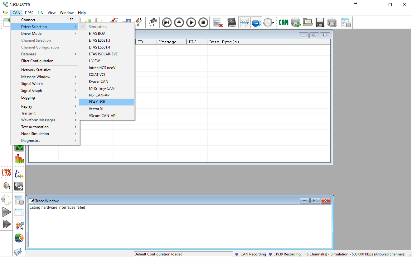
- Under the CAN menu go to Driver Selection and select PEAK USB
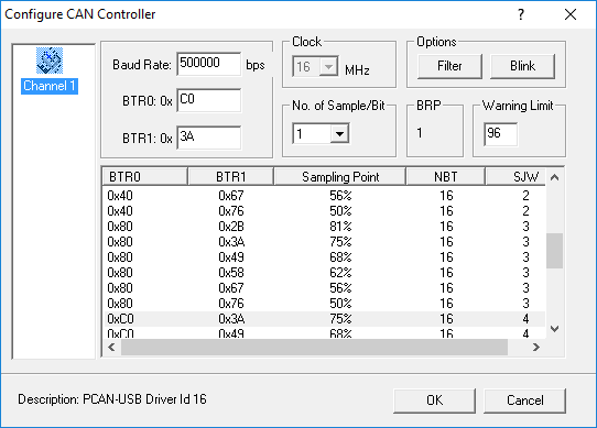
- Under the CAN menu go to Channel Configuration and change the Baud Rate to match your CAN bus and click OK.
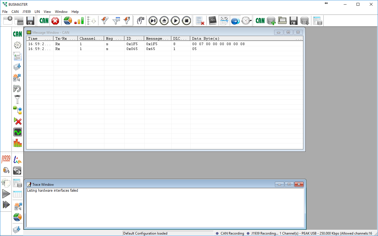
- Under the CAN menu click Connect
- If everything went correctly you should now start receiving any messages that are being sent on the CAN bus.


Now that we are receiving messages the next step is to get them to decode properly. That way we can see the physical values of the messages instead of the hex values of the raw data frames. To do this we need to attach a database file to this configuration. Since the DBC file format is proprietary BusMaster uses a similar file type called DBF instead. However, BusMaster comes with a function that will allow us to convert DBC files to DBF files. Please follow the instructions below to convert your file and attach it to this instance.
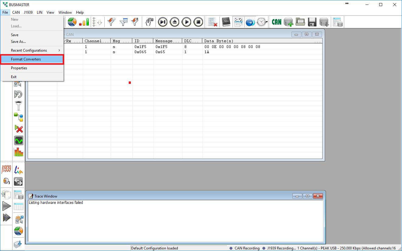
- Under the File menu go to Format Converters
- Select the Other Converters tab and then choose DBC to DBF in the drop down menu
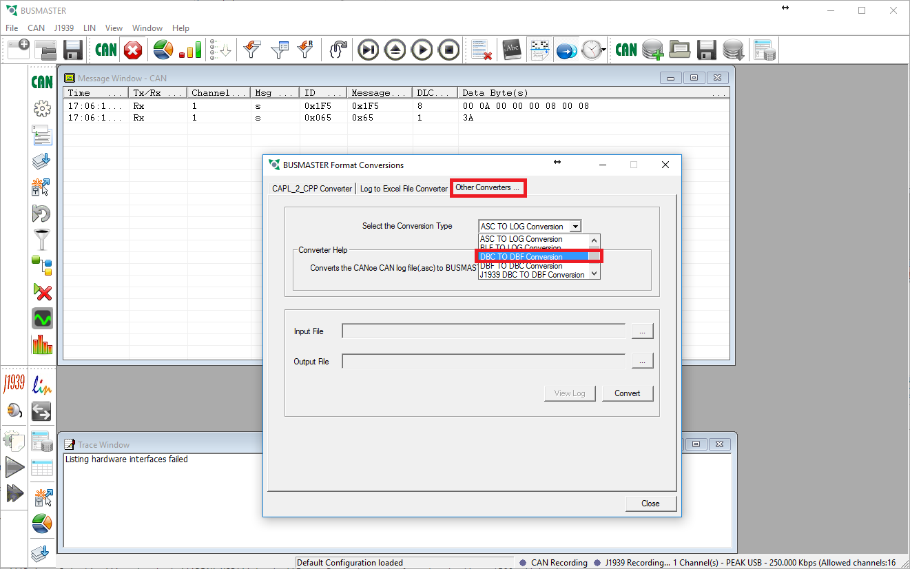
- Choose your DBC file as the Input File. The Output File's name and location will be the same as your DBC file except with the extension of .DBF. Close the dialog box when the conversion is complete
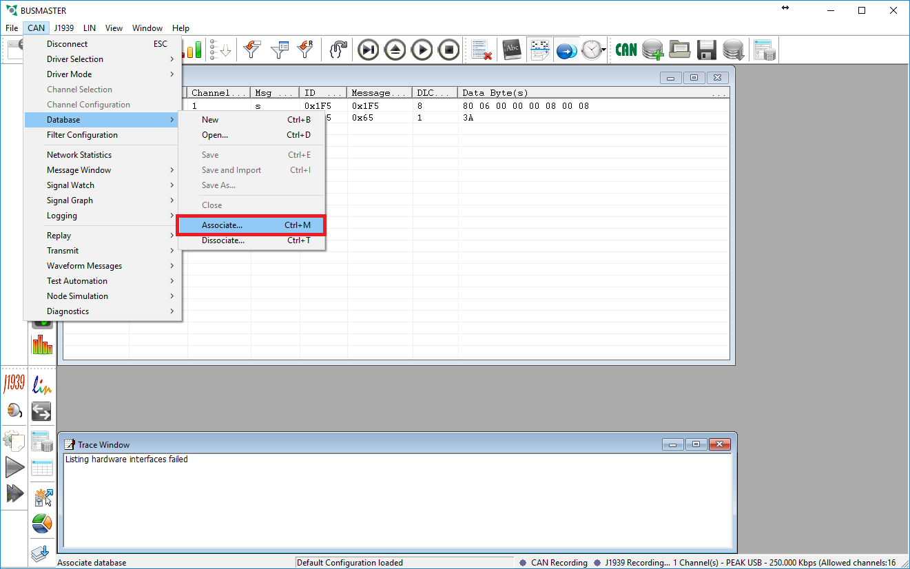
- Under the CAN menu go to Database then select Associate and choose the newly converted DBF file.
- The Message Window should now show the correct names for the messages on the bus. The next step is to interpret the signals in the messages so that we can see what the physical values are.
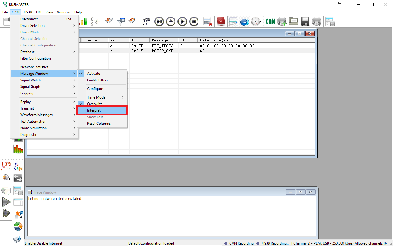
- After enabling the interpret function you will see a small + box next to the messages. If you click this box the messages will expand and show you the individual signal values.
- Now would be a good time to save you configuration in case your settings get reset so that you do not have to reconfigure BusMaster.


Useful Functions in BusMaster
Transmitting Messages
BusMaster allows you to transmit messages on the CAN bus as if it is an ECU. When these messages are put out on the bus they will act like every other message. This can be useful if you are trying to test how your ECU will react to certain messages or if you need to simulate a hearbeat signal to prevent error handling logic to take over.
- Under the CAN menu select Transmit then Configure
- To configure a message simply double click on the [Add Message] line and select the message you wish to translate on the bus.

- After selecting the message you want to send you may change the value of each signal found within that message.
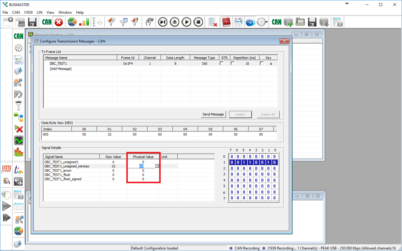
- If desired you may check the Repetition box to allow the message to be sent periodically.
- To send the message you may either select it and click the Send Message button.


Graphing
You may find it beneficial to be able to see a graph of the values that are being reported over CAN. The graph allows us to watch how values are changing over time, for instance how a sonar sensor is reporting objects in its view.
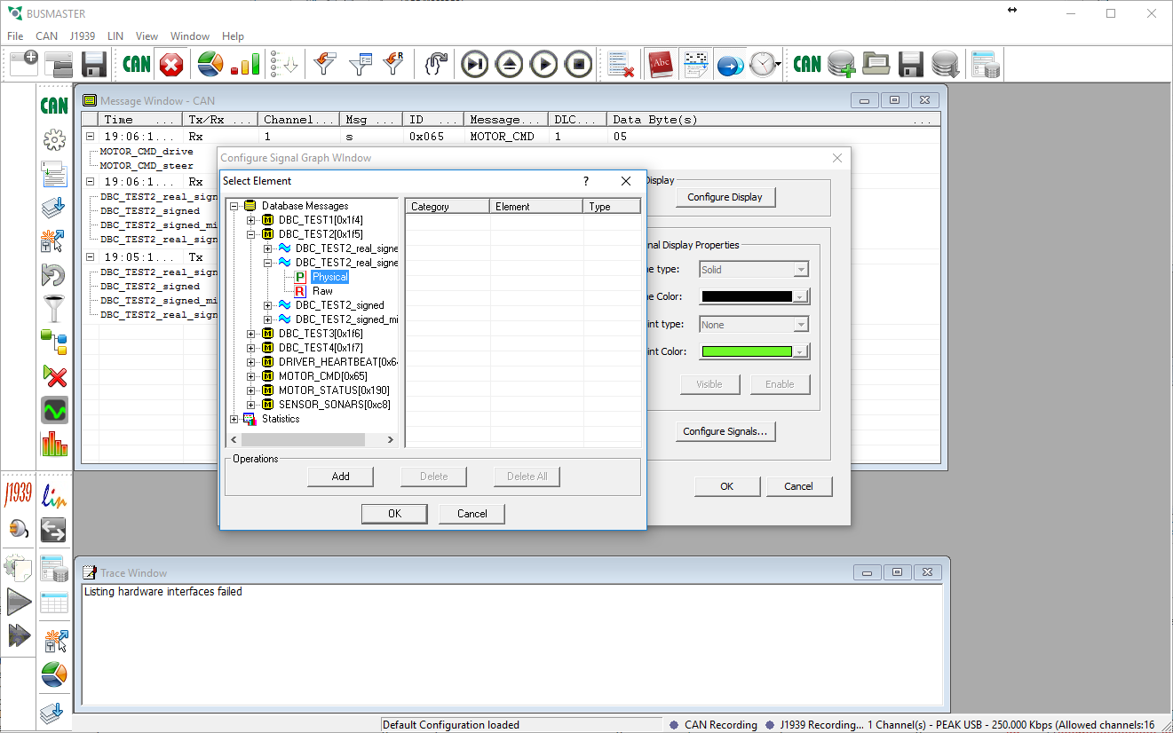
- Under the CAN menu select Signal Graph then Configure. From the dialog box that pops up click the Configure Signals button. A second dialog box will pop up that allows you to select which signal you want to graph.
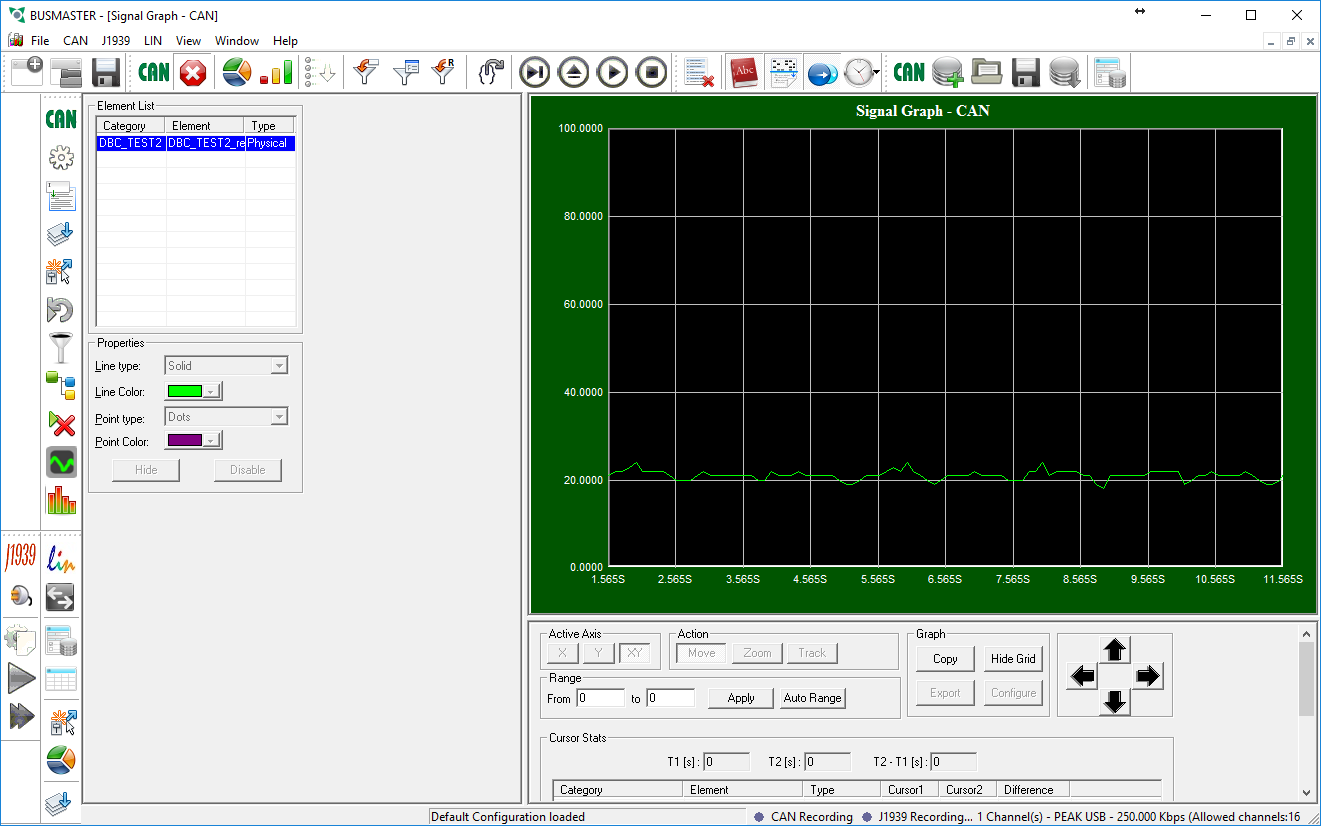
- After selecting the signal(s) you want to graph and adding them you may click OK to close all the dialog boxes. Now go to the CAN menu select Signal Graph then Activate. A new window should now show up with real time graphing of the signals you chose.


Logging
Coming soon!
Replaying Logs
Coming soon!
Troubleshooting
Coming soon!