S12: Remote Controlled MP3 Player
Contents
Remote Controlled MP3 Player
Abstract
This particular mp3 player will be implemented onto the LPC2148 micro-controller. Digital signal processing was required in order to properly detect and decode infrared receiver (IR) signals from a common television remote. There were many challenges encountered especially when dealing with the decoding of each particular signal that came from the user remote. Properly decoding the signals was essential in order to have a basic functioning remote controlled mp3. The TSOP1236 IR receiver was used to detect the signals from the user remote and actually took care of the analog to digital conversions. Overall the many challenges encountered were overcome, resulting in a remote controlled mp3 player which could utilize all basic functions except fast forward and rewind.
Objectives & Introduction
INTRODUCTION
The main concept that was involved in implementation the remote controlled mp3 player was analog to digital conversions and IR signal decoding. The TSOP1236 IR receiver was chosen due to the capabilities it has for automatically decoding the analog signals from a remote controller into digital signal. Other than the TSOP1236 receiver, no other major parts were included in the design. The devices used were necessary in order to allow music to be played on a headset. These devices included the STA013 mp3 decoder which receives an input via a serial input interface (SPI) and decodes the data producing a digital output. This digital output must then be sent to a digital to analog converter (DAC) such as the PCM1774. The devices will be receiving and sending data through an application programming interface (API) which must utilize CPU scheduling techniques. These CPU scheduling techniques must make use of the functions provided by the “FreeRTOS” library which will enable it to become a real time operating system (RTOS). Using the functions provided in the FreeRTOS library, multiprocessor synchronization would be possible. The tasks which will be later described had to be properly synced in order to allow the functionality of the remote mp3 player. The list below displays the objectives for implementation of a remote controlled mp3 player onto the LPC2148.
Objectives
- Create a circuit that would connect the TSOP1236 to an LPC2148 pin, where the input of the pin would be active low.
- Hookup the TSOP1236 IR receiver to pin on the LPC2148 that was capable of being configured as an external interrupt.
- Write the TSOP driver for the LPC2148 pin selected to be an external interrupt by performing bit manipulations to properly set the register values required.
- Create an Interrupt Service Routine (ISR) that sends time stamps of the falling edges of the clock to the TSOP decoder task.
- In TSOP decoder task, receive the time stamps of the falling edges of the clock and perform IR decoding of the time stamps collected.
- Create multiple queues using FreeRTOS for communicating between tasks.
- Based on the button pressed from the user remote, perform a particular function such as start the mp3 player, stop, pause, next track, etc.
Team Members
- Thomas Pantels
Roles & Responsibilities
The roles and responsibilities involved properly accomplishing the objectives described above. The responsibilities specifically were proper time management in order to accomplish the functioning remote controlled mp3 player. Research and full understanding of the intercommunications process that needed to be performed between tasks. Knowing how decoding of the digital signal from the TSOP1236 was done and how the data collected was interpreted in order to properly derive a decoding scheme.
Parts List & Cost
Part Cost ($) Quantity
- LPC2148 microcontroller 59.99 ( 1 )
- TSOP1236 IR Receiver 1.37 ( 1 )
- 1 kilo-ohm resistor 0.10 ( 2 )
- Female-Male jumper cables 4.50 ( 1 package )
- 4MB SD card 9.99 ( 1 )
- 86x65x8mm Breadboard 4.55 ( 1 )
Design & Implementation
The design section can go over your hardware and software design. You can have two sub-chapters here.
Hardware Design
This section will describe the communication buses used as well as how they function, the hardware configurations performed in order to properly setup the pin selected to receive an active low input. The following sections will give details on the external setup of the physical hardware involved as well as the internal configurations performed on the registers.
External Circuit
The first thing that had to be done was setup the TSOP1236 to output active low signals from the Vout (pin 3) to the pin selected. The pin selected for this particular remote controlled mp3 was P0.9 which means pine function select register 0 (PINSEL0) and pin 9 on that register. The reason for selecting P0.9 was because P0.9 could be configured as an external interrupt pin (EINT). This is required in order to interrupt the song being played to perform a function according to the new user pressed button on the remote. Any pin that can be configured as an external interrupt (EINT1 to EINT3) could have been selected. When a user presses the button on a remote an analog signal is sent out for the TSOP1236 (TSOP) to decode and produce an active low digital output to P0.9.
The figure below shows the circuit used to connect the LPC2148 to the TSOP1236 with an active low input on P0.9.
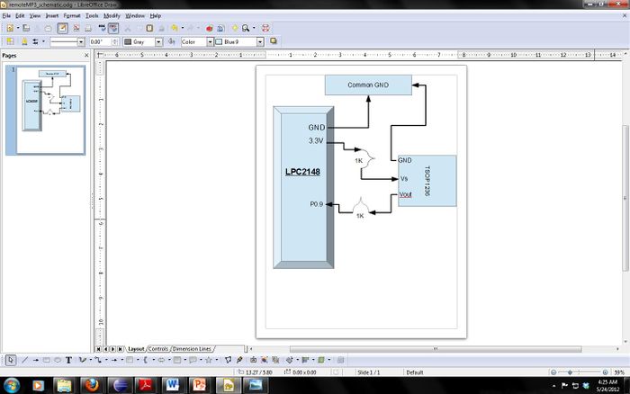
Figure 1: LPC2148 and TSOP1236 connection
It is important to notice the 1 kilo-ohm (1k) resistors used within the circuit. This is because the electric characteristics for the TSOP state that the current going into pin 2 (Vs) must not exceed a maximum of 0.45 mA. The voltage source is 3.3V thus a resistor value of 1k is used so I = 33mA. Also the resistors are used in case the P0.9 is accidentally configured to an output port direction as opposed to an input port direction, the resistors will ensure that no permanent damage to the pints occurs. The characteristic equation below was used to determine the proper resistor values to use in figure 1. A resister value of 1KΩ was used due to the calculation result of equation one below.
Rpullup = (3.3V – VLED ) / IOH (1)
Where VLED = 1.7V and IOH = 3.0 mA and is the output current coming from P0.6. The GND and 3.3V.
The locations of the pins described in figure 1 are displayed below in figure 2 [1].
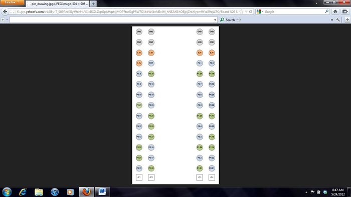
Figure 2: Pin diagram [1]
Hardware Interface
The above section described the external hardware constructed; this section will give details as to the inner workings of the LPC2148. Specifically it will describe which communication buses are used, how they are used to communicate between each device within the LPC2148. As briefly said in the introduction section, the main internal components used for achieving mp3 player functionality are listed below.
- STA013 MP3 Decoder
- PCM1774 DAC
- PCA9535 Port Expander
- SD Card
See appendix for datasheet references.
Serial Peripheral Interface (SPI)
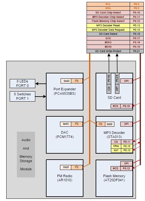
SPI, is a full duplex serial synchronous bus, it is often referred to a 3 or 4 wire bus as it requires at least 3 to 4 wires. The first three wires are MOSI (Master Out, Slave In), MISO (Master In Slave Out) and SCK (clock). The fourth line is CS (Chip Select) signal which is used to select a slave device. There can only be one active master and one active slave in a communication. Master configures the clock to start communication at a frequency equal to or less than what the slave supports. The block diagram in figure 3 shows how all these internal devices are connected and the communication buses used.
Figure 3: Component connections Block Diagram [1]
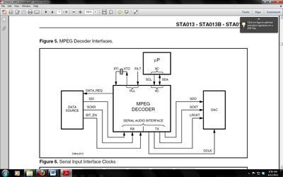
Figure 4: mp3 Decoder Data Transfer Block Diagram [3]
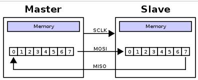
As Fig. 4 shows the two buses required are the I2C and SPI bus. The DATA_REQ_ENABLE register is a data request signal, it is configured on and put into a function labeled “STA01_NEEDS_DATA()”. The following figures show how SPI works, understanding of this bus was essential considering that 512 bytes would be sent to the STA013 mp3 Decoder module at a time on this bus. The block diagram that shows how a master and slave are connected on an SPI bus is displayed below. [1].
Figure 5: SPI Master Slave Connections[1]
The how bytes of data are transferred between the master device and the slave device on an SPI bus, in this case the master is the LPC2148 micro-controller sending data to the STA013.[1]
Figure 6: SPI Data Transfer Block Diagram [1]
I2C BUS
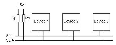
The second serial communication bus utilized was the inter integrated circuit (I2C) bus. The I2C bus is a half-duplex multi-master serial synchronous bus, it often consists of 2 wires. One wire is the serial data line (SDA) and the other is the serial clock line (SCL), the SCL and SDA lines are connected to all the devices on the bus. Communication is done by adding a third wire simply connected to ground for alternating between master and slave. Both the SCL and SDA lines are “open-drain” drivers, this means that the output can be driven low but not high. Thus for the line to go high, a pull up resistor is required and must be calculated appropriately. The block diagram of how an I2C bus looks is shown below. The I2C bus block diagram illustration is shown in figure 6 below. [2]
Figure 7: I2C Bus [1]
More information on these two buses are attached in the appendix but now that understanding of these two buses is achieved, proper APIs can be written so that implementation of a remote mp3 can be obtained.
TSOP1236 IR Receiver Driver Implementation
This section will be broken into three three sub sections listed below.
- TSOP1236_Init()
- tsopISR()
- tsopDecoderTask()
The first objective that must be met is properly configuring the P0.9 pin to be an input port and external interrupt. This initialization must be performed or else the remote mp3 will not function at all. The setup for configuring P0.9 to the proper register values is given below.
- Set bit value for PINSEL0 register to pin 9 and configure pin 9 to the third bit for EINT3.
- Use the I0DIR0 register to configure P0.9 to an input port.
- Set the external interrupt register values to the proper settings such as EINT3 being edge triggered, active on falling edge of clock and lastly clear the EINT3 pin so that future interrupts on the pin can occur. Note it is VERY important to properly clear EINT3 after receiving every interrupt, if not performed then future interrupts will never occur.
- Configure the Vector Interrupt Controller (VIC) registers to the proper values, the registers that must be configured are shown below in figure 8.
VICIntSelect &= ~(1 << 17); // use as IRQ EINT3
VICVectCntl1 = (1 << 5) | 17; // enable IRQ & select EINT3
VICVectAddr1 = (unsigned int) &tsopISR;
VICIntEnable = (1 << 17); // enables EINT3
Figure 8: Configuring VIC registers
The reason for each registers bit manipulation is described in the comments in figure 8.
- Steps 1 – 4 show the initialization process for the TSOP driver, the source code attached in the appendix is specifically for P0.9. Table 1 below shows the register values and bit settings for each register that is performed in the TSOP1236_Init() function.
TSOP Driver Register Descriptions
Register Description Bit Value
- PINSEL0, Pin select register 0 18, 3
- IODIR0, Port direction control register 9 0
- EXTMODE, External Interrupt mode 3 1
- EXTPOLAR, Rising or Falling Edge type EINT 3 0
- EXTINT, External interrupt flag 3 1
- VICIntSelect, Use EINT3 as IRQ 17 0
- VICVectCntl1, Enable IRQ & select EINT3 5 | 17 1
- VICIntEnable, Enables EINT3 17 1
Table 1. TSOP1236 Driver Initialization
Lastly the address of the ISR must declared by assigning the address of the tsopISR function to the VICVectAddr1 register. Also the tsopISR must be declared as a naked attribute so that proper context saving can be performed once an interrupt happens. FreeRTOS automatically will save the current state of the mp3 player if this attribute is used and it is indeed required.
tsopISR
Once the initialization of the TSOP driver was performed, the next task was to write the ISR which would repeatedly get the time stamps of the falling edges of the clock once a remote control button was received. The ISR would get this value from the T1TC (Timer 1 clock counter). The tsopISR function is small because it is ideal to have an ISR as short as possible, this is why in here, simple context saving is performed and the time stamp value is received from the T1TC and immediately sent to the tsopDecoderTask function. FreeRTOS has a special API called xQueueSendFromISR() that must be used in order to properly send the time stamp item to the decoder task.
tsopDecoderTask()
The decoder task’s sole function is to receive the time stamps sent to it by the ISR and decode these time stamps so that detection of when a user presses a specific button can be made. It is here where most of the technical challenges were encountered for implementing the remote mp3 player. At first nothing but random numerical values in hexadecimal notation would be displayed throughout the entire screen. It is here where detections of patterns between numbers was attempted numerous amounts of times. The process for receiving the time stamps of each falling edge of the clock is listed below in the following steps.
- Create a Queue that can hold 30 items of unsigned integers, this size was selected because the period for the TSOP1236 is 30 pulses.
- Wait forever for a signal to be put onto the queue from the ISR
- Once the first time stamp item is received gather as many time stamps as possible within a 10 ms time frame or until 128 time stamps have been collected.
- Assign each incoming timestamp to an array after subtracting the time stamps value from the initial time stamp that was received first.
- Since the time stamp counts are in micro-seconds, rounding is performed since the margin of error is small.
- Here is where the main decoding takes place, an excel sheet was used to compare each time stamp value of a particular button. It was noticed that occasionally there would be an extended period of time for a falling edge to occur. Detective reasoning was then used to assume that the extended period of time for a falling edge would be unique per signal from the remote control.
- Next the differences between each time stamp was calculated and if there was a difference larger than the number 18, then the current cell number would be logical ORed and assigned to the unsigned integer “decodedSignal”.
- Once the “decodedSignal” was determined for each button on the remote, a switch case statement was used to determine which switch value should be sent to the buttonMonitor task (discussion on this later).
Software Design
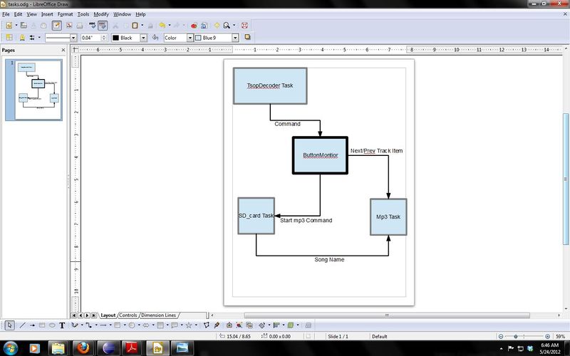
This section will describe the functionality and methodology used for each task as well as the inter process communications done between each. This section is divided into three sub sections. The block diagram illustrating the communications done between each task is displayed below. It is important to note that although the figure does not show the Queues used, communication between each task is done strictly using a specific Queue to communicate between only 2 tasks at a time. Table 2 will show this more clearly below. The inter process communication block diagram for all the tasks is displayed below in figure 9.
Figure 9: Task Communication Block Diagram
These are the four main tasks used to implement the functions of the remote mp3 via sending and receiving items on Queues. The first was the tsopDecoderTask (previously described), the remaining task descriptions are given below.
buttonMonitor Task
This is the main controller task, it is this task which receives any and all items sent from the tsopDecoderTask in the driver. Once a particular item is received, there a multitude of if conditional statements which will send a particular item to another task or simply perform a function such as volume up or down. The buttonMonitor task can be thought of as the manager of all functions that should be executed.
MP3 Task
This task specifically receives items from both the buttonMonitor task and the SD_card task. The main focus of this task is to continuously stream bytes of data to the STA013 decoder. There is a vector container declared here so that constant reopening of directory folders will not have to be done and thus decrease performance. The vector contains all of the song names on the SD card that the user desires to play. It will repeatedly wait forever for items from the SD_card task until an item named “done” is received, at this point it breaks out of the loop and proceeds to open the first song name file to play. After bytes have been streamed there are conditional statements to check if it is the last block of data from the song or if an item from the buttonMonitor task has been received. It is here that the functions of next song track and previous song track are written.
SD_card Task
The SD_card task repeatedly checks if an item has been received from the buttonMonitor task. If the item has been received then opening of directories in the SD card proceeds and if file names with the extension “.mp3” are found, they are put on the songNameQueue for the mp3 task to receive.
Task Queues
  Queue Name	               Description	              Size	Datatype
   ctrlToSD	    Send start command to start mp3 player	1	     int
   trackCtrl	    Commands for next track & previous track 	1	     int
    Mp3CTRL	    Commands from tsopDecoderTask	        2	  Unsigned int
 songNameQueue	    Contains names of songs from SD card	13	    Char
Table 2. Queues Used between each Task
Implementation
A) SD_card Task
- Reference the FatFs code in the “ls” command and read the function descriptions that are on the website elm-chang.org/fsw/ff/00index_e.html.
- Receive OSHANDLE and enter infinite loop.
- Check to see if an item on the “ctrlToSD” queue has been received, if item is “0” then proceed to step 3, else repeat step 2.
- Make FatFs objects and locate file to open in directory, find file name.
- Parse file name for “.mp3” and send to queue if there is a match.
- Have an SD detect function and write protect function.
- Copy and paste the “ls” code, then modify the code in order to correctly parse for .mp3 files specifically.
- Find the song name which is stored in the variable “Finfo.fname[0]” and send it to the songNameQueue with a max blocking time of six minutes should the queue be full.
The pseudo code used for completing steps 1-3 is displayed below in figure 10.
If command matches “0” do the following
{
Make FatFs objects
DIR dir;
FILINFO finfo;
FRRESULT returnCode = FR_OK;
Use LFN
perform error checking
  Infinite loop
  {
    Get file name from directory on SD card.
    cString.endsWith(“.mp3”) == 0) ?
    yes then put song name on songNameQueue
  }
}
Figure 10: SD_card Task pseudo code
B) mp3 Task
- Receive OSHANDLE and enter into an infinite loop.
- Declare buffer variables and check if there is something on the queue via xQueueReceive().
- If item received then push into songNameVector container and continuously receive items until the item “done” is received.
- Open file name and take Semaphore to guard resources during byte streaming to mp3 decoder and chip select mp3 decoder.
- While byte streamed is less than bytes read and STA013 needs data then send the bytes streamed via SPI.
- Deselect mp3 decoder and give semaphore back.
- Test if byte to read does not equal bytes read to know if on last junk of read data and break form infinite loop or if an item on the “trackCTRL” queue has been received.
- If an item has been received use a flag to determine whether a rotateRight() (next track) or rotateLeft() (previous track) operation should be performed.
C) buttonMonitor Task
- Initialize and configure port expander (PCA9535) registers to inputs and outputs via I2C bus.
- Always check I2C device for register input and assign to a variable of type char then do a vTaskDelay(100) to allow proper button input readability.
- Test the char type variable (pushButtonData) and perform particular mp3 function corresponding to button press.
- Depending on volume up/down controls, adjust LEDs to indicate current volume setting.
Testing & Technical Challenges
Technical Challenges
Numerous amounts of tests were performed in order to verify functionality of a particular mp3 player operation. Each individual function was functionally tested and verified, it was during this functional verification process where debugging was done. Multiple issues would arise involving improper functionality, cases ranged from mp3 player not being able to start to the mp3 player not being able to go to the next song or previous song. It was here where multiple processor synchronization errors occurred either due to a Queue blocking for too long or a task not taking the semaphore in order to guard the resources for a specific time. Errors ranged from data accept ions to stack overflows.
Apart from the process synchronization issues encountered, the most challenging technical issue that was encountered was decoding of the IR signals into consistent opcodes that could be later sent to the buttonMonitor task. It is here where the knowledge of data collecting and interpreting of that collected data was weak. Eventually all of these technical challenges were overcome resulting in a basic functioning remote controlled mp3 player. It should be noted however that due to the amount of challenges encountered, time constraints made it not possible to implement two key feature of an mp3 player. The fast forwarding of a song and the rewinding of a song.
Testing
Testing of the mp3 player resulted in having the functions of those listed in table 3 below.
  Mp3 Player Function              Functional ?
    Start mp3 player	                Yes
       Volume Up	                Yes
       Volume Down	                Yes
         Pause	                        Yes
         Resume	                        Yes
     SD card detection 	                Yes
   Volume level indicators via LEDs	Yes
    Stop mp3 player	                Yes
    3-D Sound Effect	                Yes
    Next Song Track	                Yes
  Previous Song Track	                Yes
    Fast Forward	                No
         Rewind	                        No
Table 3. Remote Controlled mp3 Functions
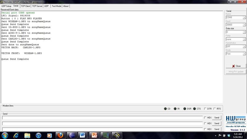
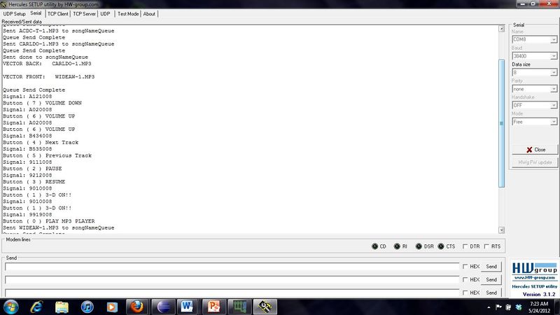
The following screenshots below show how debugging was performed, the terminal used was Hercules and each new program was loaded onto the LPC2148 using HyperTerminal. Testing was done by inserting rprintf statements in key locations, for verification, displaying the back and front of the songNameVector would take place before opening the first song. This was done to verify that all of the songs on the SD card had been properly pushed onto the vector.
Figure 11: Functional Debugging Screenshot of Hercules
Figure 12: Debugging rprintf statements for checking multiple operations
Conclusion
Implementing a remote controlled mp3 player onto the LPC2148 was no easy task; multiple issues were encountered resulting in not being able to perform fast forwarding and rewinding of a song. Although these two objectives were not met, the remote controlled mp3 player still is suitable for a common user’s needs. The biggest obstacle for implementing the remote controlled mp3 was seeing lines of random data and trying to interpret it. The use of multiprocessor synchronization is essential if one is to implement an mp3 player. The remote controlled mp3 player adds to this by requiring external interrupts to be configured and IR signal decoding. There are multiple ways the remote controlled mp3 player could have been implemented, one could have made use of a time capture in which specific snapshots of the falling edge of the clock are made. This capture timer approach however involves more time and knowledge to implement and thus was rejected in favor of time stamps. Essentially using the time stamps to indicate the falling edge of the clock, a decoding scheme had been made which is specific to the remote that is to be used. Each remote controller has different signals that are outputted when a button is pressed, the source code attached in the appendix is specific towards a particular remote. If one desires to use a different remote controller however, one would simply need to display the signal value as shown in Fig. 10 and rewrite an enumator to pertain to the new remote. The remote controlled mp3 player involves knowledge in real time operating systems, interrupts, bit manipulations, IR decoding and over all digital signal processing. One must also utilize Queues for communication and semaphores for entering critical sections or guarding a particular resource.
References
Acknowledgement
Local classmates and peers in the classroom helped with debugging and showing where to go to find certain information needed specifically Yoni Klein for some methodology advice. Also Preet for assistance and sharing of knowledge on IR decoding.
References Used
[1] P. Kang, “References, software tools and datasheets for the LPC 2148 microcontroller”, Computer Engineering Department, College of Engineering, San Jose State University, Jan 27, 2012.
[2] LPC 2148 User Manual [Data file], (2005), Koninklijke Philips Electronics, N.V.
[3] STA012 User Manual [Data file], (2004), STMicroelectronics, United States.
[4] PCM1774 User Manual [Data file], (2009), Texas Instruments, Dallas, Texas.
Appendix
File:CmpE146 S12 T8 SourceCode.zip
Other Hints (Do not include this)
- You may want sub-sections by using three equal signs.
