S14: Androbot
Contents
Project Title
ANDROBOT
Abstract
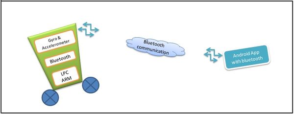
Androbot is a self balancing robot. The robot maintains it's balance using the IMU 6050 sensor. The values of accelerometer and gyroscope from the IMU sensor help in controlling the stepper motor. The wheels are connected to the stepper motor. The movements of the robot can be controlled using a Android phone app via Bluetooth.
Objectives
Objectives.
- To develop a self balancing robot using accelerometer and gyroscope sensor.
- To control the motion of the robot using Bluetooth module.
- To develop an Android application for the motion control.
Team Members & Responsibilities
- Digvijay Patil
- Driver Development + Android App Development
- Mahesh Chudasama
- Mechanical Design + Hardware
- Shashank Tupkar
- FreeRTOS Software Design + Android App Development
Introduction
The idea of this project was to design and construct a robot that can be balanced and driven on two wheels. This behavior is similar how a segway (a new mode of transportation) works. The project aims to control the motion or direction of the robot through Android app via bluetooth module.Our goal was to have a working finished product – a robot that, without human interaction, could balance on two wheels.
Schedule
| Week# | Date | Task | Actual |
|---|---|---|---|
| 1 | 03/6 | Project role distribution | Completed |
| 2 | 03/13 | Partlist discussion and Block Diagram | Completed |
| 3 | 03/16 | Partlist finalization and Circuit Schematic | Completed |
| 4 | 03/20 | Ordering parts and components | Completed |
| 5 | 03/27 | Mechanical assembly, Hardware and Android app layout, Interfacing GY 521 With SJ One Board | Completed |
| 6 | 04/03 | Hardware test and Kalman Filter firmware coding | Completed |
| 7 | 04/10 | Test and debug part (a) Self balancing robot | In progress |
| 8 | 04/17 | Android app creation for Bluetooth module testing | Completed |
| 9 | 04/24 | Integrating Android app with Bluetooth module | Completed |
| 10 | 05/01 | Testing and debug | Not Completed |
| 11 | 05/08 | Testing and debug | Not Completed |
| 12 | 05/15 | Demo | Not Completed |
Parts List & Cost
The table below summarizes the parts used and the cost for the Androbot project till now. (To be completed)
| Sr. No. | Part | Description | Qty | Total Cost |
|---|---|---|---|---|
| 1 | SJOne Board | ARM Cortex M3 | 1 | $80.00 |
| 2 | Stepper Motor 1.8* | NEMA 17 12 V Step size = 1.8* Imax = 400 mA |
2 | $12.99 |
| 3 | Wheel | Diameter : 9 CM Width : 0.5" |
2 | $9 |
| 4 | Shaft Coupler | To couple wheel with motor shaft | 2 | $6.99 |
| 5 | ULN2004 IC | Motor driver IC Number of Buffers inverter/IC : 7 Imax = 500 mA |
2 | $0.65 |
| 6 | 16 Pin IC holder | To hold ULN2004 IC , So in case of IC failure, we can replace it immediately | 2 | $1.3 |
| 7 | IMU6050 | 6 Axis Gyro + Aceelerometer +- 1.5 g |
1 | $7 |
| 8 | Battery- Light weight | NIMH = 12V 2000 mAH Weight : 434 oz |
1 | $19.99 |
| 9 | HC-05 Bluetooth Module | Sensitivity : 80 dBm Operating Voltage : 1.8 to 3.6 V Output : UART Data rate : Variable |
1 | $12 |
| 10 | Chassis | Made from plastic tiffin box by cutting it from 3" Height | 1 | $6 |
| 11 | Strip connector | To connect development board with prototype board | 2 | $3 |
| 12 | Prototype Board | For implementing driver circuitry | 1 | $5 |
| Total Cost | $163.92 |
Design & Implementation
Hardware Design
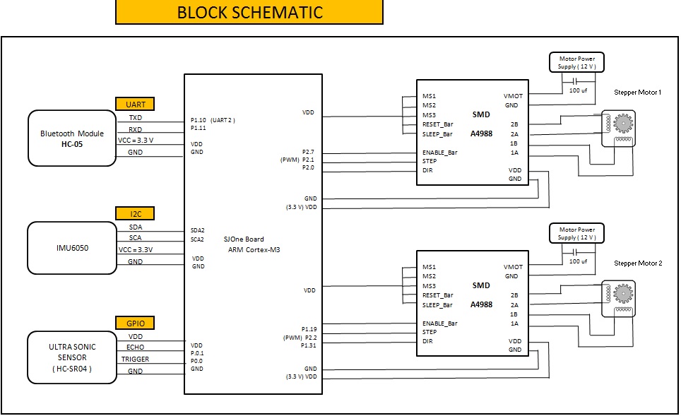
The above figure shows the detailed schematic of the project. It shows the interfacing of SJ_One Board with different modules along with their pin connections. It also shows the the communication protocols used for interfacing the modules.
The following modules are interfaced with SJ_One Board:
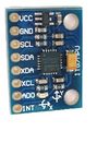
1. MPU6050 orientation detection sensor MPU6050 is a 6 degree of freedom (DOF) Accelerometer + Gyroscope chip from InvenSense. It is the world’s first integrated 6 axis MotionTracking device that combine 3 axis gyroscope, 3 axis accelerometer and a Digital Motion Processor™ (DMP) all in a small 4x4x0.9mm package. It operates at a 3.3V or 5V supply and communicates via I2C at a maximum speed of 400kHz. It comes with the breakout board called GY-521.
2. HC-05 Bluetooth module HC-05 Bluetooth module Bluetooth SPP (Serial Port Protocol) module, designed for transparent wireless serial connection setup. Features-
- Default Baud rate: 38400, Data bits:8, Stop bit:1,Parity:No parity, Data control: has.
- Supported baud rate: 9600,19200,38400,57600,115200,230400,460800.
- Master and slave are paired, red led blinks 1time/2s in interval, while disconnected red blinks 2times/s.
- Permit pairing device to connect as default.
3. HC-SR04 Ultrasonic sensor Ultrasonic ranging module HC - SR04 provides 2cm - 400cm non-contact measurement function, the ranging accuracy can reach to 3mm. The modules includes ultrasonic transmitters, receiver and control circuit. The basic principle of work: • Using IO trigger for at least 10us high level signal, • The Module automatically sends eight 40 kHz and detect whether there is a pulse signal back. • IF the signal back, through high level , time of high output IO duration is the time from sending ultrasonic to returning. Test distance = (high level time × velocity of sound (340M/S) / 2, Sensor is interfaced with P0.0 and P0.1 GPIO pins of SJSUone board where P0.0 will act as trigger and P0.1 as echo input to sense the value.
4. Stepper motor driver.
- ULN 2003
Initially we have used ULN 2004 DIP which is inverted buffer which are the standard Darlington arrays. The outputs are capable of sinking 500mA and will withstand at least 50 V in the OFF state. Outputs may be paralleled for higher load current capability. But this mode provide the full step mode and good torque but robot faces jerk as we cannot implement deceleration logic with ULN 2004 so we need micro stepping driver which will divide the steps further in smaller ones.
- A4988 micro stepping driver-
The A4988 is a complete microstepping motor driver with built-in translator for easy operation. It is designed to operate bipolar stepper motors in full-, half-, quarter-, eighth-, and sixteenth-step modes, with an output drive capacity of up to 35 V and ±2 A
Mechanical Body
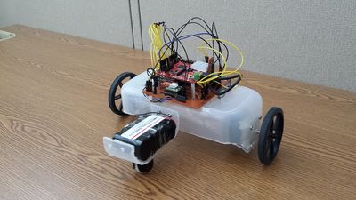
The mechanical structure for the robot is designed using a plastic container. The plastic container is mounted on two stepper motors. The shaft of the stepper motors are connected to two wheels. The PCB along with the SJ One board and the different modules is mounted on the plastic container which manages the motion of the robot.
Hardware Interface
This section describes the actual physical hardware devices used in the project.
1) Battery
Stepper motors are open-loop controller so we have selected as basic building block stepper motor. On the other hand NEMA stepper motor requires power source which can deliver 4-5 W and with 12 V supply our requirement was of 400mA per phase to drive the stepper so altogether 1600mA was the expected drain we calculated for 4 phases of 2 motors. In addition 5v power supply with IC 7805 is built up to drive SJSU-One board, Ultra-sonic and GPU sensor. With these requirement there were following options of Rechargeable battery choice 1. Lithium-ion batteries are common one they are one of the most popular types of rechargeable battery for portable electronics, with best energy densities i.e. with higher sourcing capacity of 4V, 2000 to 3000mAh but these batteries need very careful charging practices and a bit expensive as compared to NiMH cells. 2. NiMH cells are is the robust choice for these type of applications, they come with 1.2V, 2200mAh ratings. The assembly of the multiple cells is used as RC car batteries in most of the robot application, typically we need 10 cascaded cell to built up 12V power supply. The reasons to select these batteries are easy charging cycles. Please find the specification of the same as below:
- Product: 12V 2000mAh NiMH Battery
- Make: Made of 10 x AA NiMH 2000mAh cells
- Connector: Bare Leads
- Fit Models: RC airplanes, such as Wattage
- Feature: Rapidly charge up and long cycle life
- Weight: 10 Oz
- Dimensions: 50mm (Width); 29mm (Height); 72mm (Length)
2) Stepper motor
The typical self balancing robot uses DC motor with encoders but we decided to go with stepper motors as new challenge. Stepper motors are characterized by their torque and looking at our chassis design we were in the need of motors with more torque. The trade off for these motor is power consumption they consume power even in static position These motors are available in National Electrical Manufacturers Association i.e.NEMA standards which has predefined structural design guidelines for manufacturing practices.
Mainly these motors can be categorized into
- Unipolar : has one winding with center tap per phase
- Bipolar: have a single winding per phase
As Unipolar motors can be used in Bipolar mode also by neglecting centre tap this will provide use flexibility in driver selection and different mode of the application.
Software Design
This section includes the software design for the module interface.
1) MPU 6050 Interface
Setup is performed by writing to the various configuration registers. You only need to write to three registers for accelerometer and gyroscope in the end, leaving the rest as zeros, however it is still good practice to write these zeros just in case the register didn't reset correctly. We used the code from the github to save time, as the header file already has the naming of every register address. I have only shown the registers which were frequently used. For all the other registers please refer the code.
- define MPU6050_ADDRESS 0b11010010 // Address with end write bit
- define MPU6050_RA_ACCEL_XOUT_H 0x3B
- define MPU6050_RA_ACCEL_XOUT_L 0x3C
- define MPU6050_RA_ACCEL_YOUT_H 0x3D
- define MPU6050_RA_ACCEL_YOUT_L 0x3E
- define MPU6050_RA_ACCEL_ZOUT_H 0x3F
- define MPU6050_RA_ACCEL_ZOUT_L 0x40
- define MPU6050_RA_TEMP_OUT_H 0x41
- define MPU6050_RA_TEMP_OUT_L 0x42
- define MPU6050_RA_GYRO_XOUT_H 0x43
- define MPU6050_RA_GYRO_XOUT_L 0x44
- define MPU6050_RA_GYRO_YOUT_H 0x45
- define MPU6050_RA_GYRO_YOUT_L 0x46
- define MPU6050_RA_GYRO_ZOUT_H 0x47
- define MPU6050_RA_GYRO_ZOUT_L 0x48
- define MPU6050_RA_WHO_AM_I 0x75
The first line defines the address of the chip, which is 0x69 since AD0 is pulled high. This value is stored in the 7 most significant bits, with the least significant bit being the read/write bit. When cleared, this tells the chip a write is about to occur and when set it tells the chip to send data from the specified register address. This setting and clearing is done by ORing the address with 0x01 for a read, or leaving it untouched for a write. This operation is performed by the I2C driver. Not all of these addresses are writable, and some aren't even mentioned in the datasheet. The first part of the setup is to check the I2C link is functioning. This is done by simply reading the register at 0x75, referred to as MPU6050_RA_WHO_AM_I. This contains the chips I2C address, which is always 0x68, regardless of the state of AD0. If this communication is successful, you know your chip functions partially, congratulations! The next step is to write to all the configuration registers. We do not know why so many registers are written but all the registers need to be written for proper functioning of the chip.
2) Kalman Filter
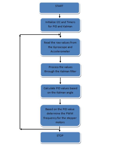
The Kalman filter is a linear quadratic estimation algorithm. It uses a series of measurements observed over time, containing noise (random variations) and other inaccuracies and produces estimates of unknown variables that tend to be more precise than those based on a single measurement alone. Kalman filter has lot of mathematical explanations and is well explained on internet. Pseudo Code for Kalman Filter:
1. Calculate delta time so that it calculates the values after particular timer
2. Calculate Roll and Pitch using atan2 function double roll = atan2(accY, accZ) * RAD_TO_DEG; double pitch = atan(-accX / sqrt(accY * accY + accZ * accZ)) * RAD_TO_DEG;
3. Calculate gyro angles in degrees /sec double gyroXrate = gyroX / 131.0;
4. Fix the transition problem when the accelerometer angle jumps between -180 and 180 degrees else calculate the angle using a Kalman filter
if ((roll < -90 && kalAngleX > 90) || (roll > 90 && kalAngleX < -90)) {
     kalmanX.setAngle(roll);
     compAngleX = roll;
     kalAngleX = roll;
     gyroXangle = roll;
   }
else
     kalAngleX = kalmanX.getAngle(roll, gyroXrate, dt);
3) PID Controller
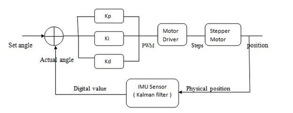
PID is an acronym for Proportional, Integral and Derivative control system. It is very efficient and popular control mechanism which provides highly stable system. PID is a close loop control system mechanism. The error signal is generated on basis of difference between set value input and feedback value. This error signal is given to the PID gain stage which generates PID controlled output required to drive the final object.
The proportional control: The proportional control gain is used to magnify the error so as to take a corrective action on motors. If only proportional control system is used, the system keeps oscillating around set point.
P = Kp * Ep
The Integral control accumulates all the error values of past so as to remove the steady state error. Integral is responsible to get the actual value to set value.
I = I + Ei
I = Ki * I
The derivative control responds to rate of change of error. Faster the error rate, faster the corrective action. We are using ‘Backward difference’ method to calculate derivative.
D = Kd * ( Ed(n) – Ed(n-1) )
PWM = P + I + D;
This PWM can be used to control the motor speed.
Implementation
Testing & Technical Challenges
Describe the challenges of your project. What advise would you give yourself or someone else if your project can be started from scratch again? Make a smooth transition to testing section and described what it took to test your project.
Include sub-sections that list out a problem and solution, such as:
Issue #1
Deciding the motors and battery. (To be completed)
Issue #2
Deciding the the body of the bot. (To be completed) We did not want our robot to be very heavy and consume more voltage.
Issue #3
- Interfacing GY-521(Accelerometer and Gyroscope Sensor) board with the SJ One board.
IMU MPU 6050 works on I2C and SPI both. We decided to go with I2C as I2C state machine was already written. There were number of issues faced here:
- Getting the proper address of the IMU for initiating the communication. The tricky part here is if AD0 pin of IMU sensor is pulled low the address is 0x68 and if its pulled high the address is 0x69. This took a while to figure out.
- MPU 6050 once it is initialized by writing the specified registers, you do not have to again write the registers for reading the data. To get the data just keep on reading the specified registers for values.
- The data in the register comes in 2 bytes with the MSB byte first. So first left shift the values of MSB by 8 and concatenate it with LSB. The difficult part is to get the data in the exact format which took while to figure as there is no basis to decide whether the data is correct or not. The data acquired and the data concatenated should be in the uint_8 format.
Issue #4
We did not use the encoders so we could not find the exact position of the wheels. We could not decide by how many steps each of the wheel rotated.
Conclusion
Conclude your project here. You can recap your testing and problems. You should address the "so what" part here to indicate what you ultimately learnt from this project. How has this project increased your knowledge?
Project Video
Upload a video of your project and post the link here.
Project Source Code
Send me your zipped source code and I will upload this to SourceForge and link it for you.
References
Acknowledgement
Any acknowledgement that you may wish to provide can be included here.
References Used
[1] http://www.cdiweb.com/datasheets/invensense/PS-MPU-6000A.pdf
[2] http://www.starlino.com/imu_guide.html
[3] http://www.botched.co.uk/pic-tutorials/mpu6050-setup-data-aquisition/
Appendix
You can list the references you used.
