F24: Space 6
Contents
Space 6
Introduction
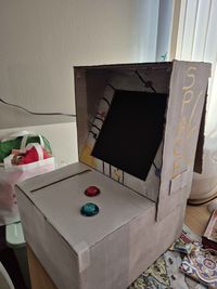
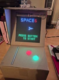
In this project, we've created a version of the classic Space Invaders game. Instead of using a traditional joystick, the player controls the spaceship's movement using a linear potentiometer that responds to touch. The spaceship shoots to destroy enemies, and the entire game map scrolls in the opposite direction of the spaceship's movement. As the game progresses, the speed of the map's flow and the number of enemies increase, adding more challenge. The spaceship's health decreases when it collides with enemies or their bullets, and the game ends when the health reaches zero.
Objectives & Introduction
- Connect a 64x64 RGB LED Matrix to the SJ-Two Microcontroller for visuals.
- Set up a separate SJ-Two Microcontroller to handle audio using the Yx5300 MP3 Decoder.
- Use the Soft Potentiometer to control the character on display.
- Enable communication between the led display and SJ2 microcontrollers using UART.Write simple code to display characters and game objects on the LED Matrix.
- Add sound effects for different parts of the game to make it more engaging.
- Create multiple screens to show different stages of the game.
- Integrate Sound, DIsplay and Gamelogic together
Team Members & Responsibilities
- Ambarish Govindarajulu Kaliamurthi
- MP3 Decoder
- Jesus Morales
- Game Logic, screen Creation
- Randy Nguyen
- LED Driver, Integration
Schedule
| Week# | Start Date | End Date | Task | Status |
|---|---|---|---|---|
| 1 |
|
|
|
|
| 2 |
|
|
|
|
| 3 |
|
|
|
|
| 4 |
|
|
|
|
| 5 |
|
|
|
|
| 6 |
|
|
|
|
| 7 |
|
|
|
|
| 8 |
|
|
|
|
| 9 |
|
|
|
|
Parts List & Cost
| Item# | Description | Quantity | Price |
|---|---|---|---|
| 1 |
SJ2C Board |
1 |
$50.00 |
| 2 |
LED Display (WaveShare 64x64) |
1 |
$85.95 |
| 3 |
Momentary switches |
5 |
$8.99 |
| 4 |
Jumper wires |
Pack |
$6.99 |
| 5 |
5V Power Supply |
1 |
$ 16.99 |
| 6 |
MP3 serial module |
1 |
$ 8.39 |
| 7 |
Linear Potentiometer |
1 |
$ 28.73 |
| 8 |
Game enclosure (wood / paint / adhesive) |
Misc |
$ 30.00 |
Design & Implementation
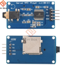
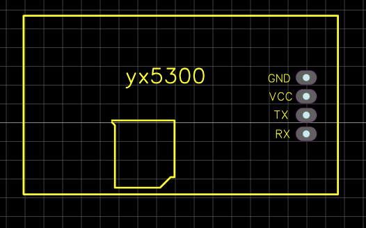
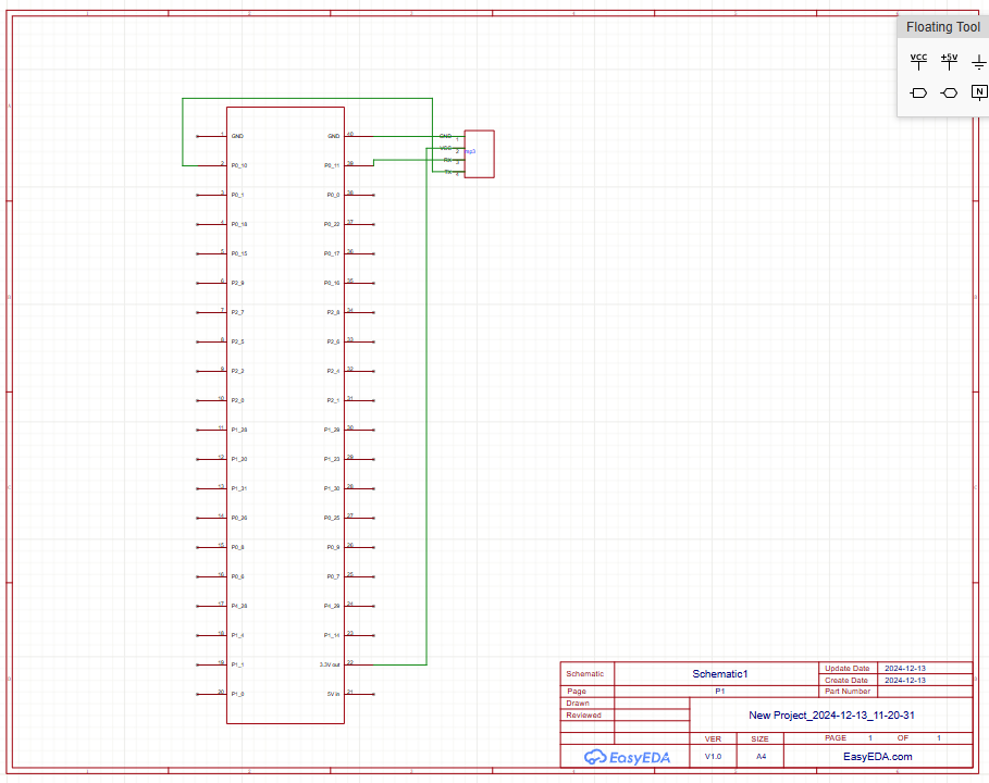
The 64x64 RGB LED Matrix connects to the SJ-Two microcontroller via GPIO pins, with additional connections for power and ground. The YX5300 MP3 decoder interfaces with the same microcontroller using UART TX and RX pins for serial communication. The decoder also has connections to an SD card for audio files and outputs audio to a connected speaker or amplifier, completing the setup for synchronized visuals and sound.
Hardware Design
Discuss your hardware design here. Show detailed schematics, and the interface here.
Hardware Interface
In this section, you can describe how your hardware communicates, such as which BUSes used. You can discuss your driver implementation here, such that the Software Design section is isolated to talk about high level workings rather than inner working of your project.
Linear Potentiometer
LED Display 64x64
MP3 Decoder
Hardware Interface and Connections
|
Connection Table: MP3 Player to SJ2 Board
|
|||||||||||||||||
Supported Specifications
- File Formats: MP3, WAV
- Sampling Frequencies: 8 kHz, 11.025 kHz, 12 kHz, 16 kHz, 22.05 kHz, 24 kHz, 32 kHz, 44.1 kHz, 48 kHz
- SD cards (≤2GB) / SDHC cards (≤32GB)
- File System: FAT16, FAT32
- UART Baud Rate: 9600 bps
- Volume Levels: 30 adjustable levels in hex
- Power Supply: 3.2–5.2 VDC (3.3V)
- Naming Songs:Name audio files as 001sng.mp3, 002sng.mp3, etc., and place them in folders like 01, 02 etc
Software Design
We developed a driver for the MP3 player module that sets up UART communication and connects the RX and TX pins properly. The driver makes it easy to send commands to the MP3 player, such as adjusting the volume, playing specific songs by their number or folder, skipping tracks, and setting playback modes like repeatt. For more details, check out the user manual: [3]
Implementation
- Initialize MP3 decorder: Get the MP3 player ready by selecting the SD card that has your songs.
- Cycle play mode: Set a song to play on repeat.
- Pause a song: Temporarily stop playback.
- Resume playback: Continue playing the song from where it was paused.
- Play by index: Start playback of a specific song using its number.
- Set volume: Adjust the playback volume to a desired level.
- Next song: Skip to the next track in the playlist.
- Previous song: Go back to the previous track in the playlist.
Code Structure
- Initialization: Call sound_manager__init() to set up the sound manager, including initializing the MP3 decoder, creating FreeRTOS tasks for each sound effect, and configuring semaphores for synchronization.
- Pin Selection: Configure the UART pins in mp3_dec.c using gpio__construct_with_function() to match your hardware setup.
- Sound Effects: Trigger sound effects using the provided functions in the sound manager:
sound_manager__play_laser();
sound_manager__play_explosion();
sound_manager__play_won_game();
mp3_decoder__play_song_at_index(0x01);
check here for more [4]
Testing & Technical Challenges
Describe the challenges of your project. What advise would you give yourself or someone else if your project can be started from scratch again? Make a smooth transition to testing section and described what it took to test your project.
Include sub-sections that list out a problem and solution, such as:
<Bug/issue name>
Discuss the issue and resolution.
Conclusion
Conclude your project here. You can recap your testing and problems. You should address the "so what" part here to indicate what you ultimately learnt from this project. How has this project increased your knowledge?
Project Video
Upload a video of your project and post the link here.
Project Source Code
References
Acknowledgement
Any acknowledgement that you may wish to provide can be included here.
References Used
List any references used in project.
Appendix
You can list the references you used.
