S23: X Æ A-13
Contents
Project Title
<Team Name>
Abstract
<2-3 sentence abstract>
Introduction
The project was divided into N modules:
- Sensor ...
- Motor..
- ...
- Android
Team Members & Responsibilities
<Team Picture>
The source code of our car can be found here: X Æ A-13 Gitlab Repository
|
Team Members |
Administrative Roles |
Technical Roles | ||
|---|---|---|---|---|
| ||||
| ||||
| ||||
| ||||
| ||||
Schedule
| Task# | Start Date | End Date | Task | Status | Point of Contact |
|---|---|---|---|---|---|
| 1 | 02/13/2023 | 02/18/2023 |
|
Completed | Team |
| 2 | 02/19/2023 | 02/22/2023 |
|
Completed | Iftiza |
| 3 | 03/03/2023 | 03/10/2023 |
|
Completed | Sharan, Prabhat, Tushara |
| 4 | 03/11/2023 | 03/17/2023 |
|
Completed | Team |
| 5 | 03/18/2023 | 03/21/2023 |
Work on the RC Car Infrastructure Task
|
Completed |
|
| 6 | 03/22/2023 | 04/04/2023 |
Work on the Geo Controller Task
|
Completed |
|
| 7 | 04/05/2023 | 04/18/2023 |
Work towards the Prototype 1 Task
|
Completed |
|
| 8 | 04/19/2023 | 04/25/2023 | Work towards the Prototype 2 Task
|
Completed |
|
| 9 | 04/20/2023 | 05/02/2023 | Work towards the Prototype 3 Task
|
Completed |
|
| 10 | 05/03/2023 | 05/09/2023 | Work towards the Prototype 4 Task
|
Completed |
|
| 11 | 05/10/2023 | 05/24/2023 | Work towards the final demo
|
Completed |
|
| 12 | 05/10/2023 | 05/26/2023 | Project Wrap-up
|
Ongoing |
Team |
Parts List & Cost
| Item# | Part Desciption | Vendor | Qty | Cost |
|---|---|---|---|---|
| 1 | RC Car | Maverick Quantum MT [1] | 1 | $180.00 |
| 2 | RC Car Battery | Lithium Polymer Two-Cell | 1 | $20.0 |
| 3 | CAN Transceiver Modules | SN65HVD230 | 4 | $43.56 |
| 4 | SJTwo Microcontroller Development Board | SJSU | 5 | $250 |
| 5 | Ultrasonic Sensor | Adafruit US 100[2] | 4 | $48.69 |
| 6 | GPS Module | Adafruit PA1616S [3] | 1 | $32 |
| 7 | Compass Module | CMPS12 - RobotShop [4] | 1 | $39.77 |
| 8 | LCD Module | LCD1602 [5] | 2 | $12.02 |
Printed Circuit Board
<Picture and information, including links to your PCB>
CAN Communication
<Talk about your message IDs or communication strategy, such as periodic transmission, MIA management etc.>
Hardware Design
<Show your CAN bus hardware design>
DBC File
Gitlab link to the X Æ A-13 DBC file
VERSION "2.5"

NS_ :
	BA_
	BA_DEF_
	BA_DEF_DEF_
	BA_DEF_DEF_REL_
	BA_DEF_REL_
	BA_DEF_SGTYPE_
	BA_REL_
	BA_SGTYPE_
	BO_TX_BU_
	BU_BO_REL_
	BU_EV_REL_
	BU_SG_REL_
	CAT_
	CAT_DEF_
	CM_
	ENVVAR_DATA_
	EV_DATA_
	FILTER
	NS_DESC_
	SGTYPE_
	SGTYPE_VAL_
	SG_MUL_VAL_
	SIGTYPE_VALTYPE_
	SIG_GROUP_
	SIG_TYPE_REF_
	SIG_VALTYPE_
	VAL_
	VAL_TABLE_

BS_:

BU_: GEOLOGICAL SENSOR DRIVER MOTOR

BO_ 101 CHKPT_GPS_POSITION: 8 GEOLOGICAL
 SG_ CHKPT_GPS_LATITUDE_SCALED : 0|32@1- (1,0) [-90000000|90000000] "degree" DRIVER
 SG_ CHKPT_GPS_LONGITUDE_SCALED : 32|32@1- (1,0) [-180000000|180000000] "degree" DRIVER

BO_ 102 CURRENT_GPS_POSITION: 8 GEOLOGICAL
 SG_ CURRENT_GPS_LATITUDE_SCALED : 0|32@1- (1,0) [-90000000|90000000] "degree" DRIVER
 SG_ CURRENT_GPS_LONGITUDE_SCALED : 32|32@1- (1,0) [-180000000|180000000] "degree" DRIVER

BO_ 103 GEO_STATUS: 8 GEOLOGICAL
 SG_ GEO_STATUS_COMPASS_ANGLE : 0|10@1+ (1,0) [0|359] "degree" DRIVER
 SG_ GEO_STATUS_BEARING_ANGLE_TO_DESTINATION : 10|10@1+ (1,0) [0|359] "degree" DRIVER
 SG_ GEO_STATUS_DISTANCE_TO_DESTINATION : 20|16@1+ (1,0) [0|2000] "meter" DRIVER
 SG_ GEO_STATUS_BEARING_ANGLE_TO_CHKPT : 36|10@1+ (1,0) [0|359] "degree" DRIVER
 SG_ GEO_STATUS_DISTANCE_TO_CHKPT : 46|16@1+ (1,0) [0|2000] "metre" DRIVER

BO_ 104 GEO_ANGLE_DELTA: 4 GEOLOGICAL
 SG_ GEO_ANGLE_DIFF_TO_DEST : 0|16@1- (1,0) [-359|359] "degree" DRIVER
 SG_ GEO_ANGLE_DIFF_TO_CHKPT : 16|16@1- (1,0) [-359|359] "degree" DRIVER

BO_ 105 GEO_LOCK: 1 GEOLOGICAL
 SG_ GEO_LOCK_TO_DESTINATION : 0|8@1+ (1,0) [0|1] "boolean" DRIVER

BO_ 201 SENSOR_SONARS: 5 SENSOR
 SG_ SENSOR_SONARS_left : 0|10@1+ (1,0) [0|1000] "cm" DRIVER
 SG_ SENSOR_SONARS_right : 10|10@1+ (1,0) [0|1000] "cm" DRIVER
 SG_ SENSOR_SONARS_middle : 20|10@1+ (1,0) [0|1000] "cm" DRIVER
 SG_ SENSOR_SONARS_rear : 30|10@1+ (1,0) [0|1000] "cm" DRIVER

BO_ 202 DEST_GPS_POSITION: 8 SENSOR
 SG_ DEST_GPS_LATITUDE_SCALED : 0|32@1- (1,0) [-90000000|90000000] "degree" GEOLOGICAL,DRIVER
 SG_ DEST_GPS_LONGITUDE_SCALED : 32|32@1- (1,0) [-180000000|180000000] "degree" GEOLOGICAL,DRIVER

BO_ 203 CAR_HEARTBEAT: 1 SENSOR
 SG_ HEARTBEAT_DATA : 0|8@1+ (1,0) [0|1] "boolean" DRIVER

BO_ 302 MOTOR_CMD: 3 DRIVER
 SG_ MOTOR_CMD_steer: 0|8@1- (1,-5) [-5|5] "" MOTOR
 SG_ MOTOR_CMD_drive : 8|16@1- (1,-9) [-9|9] "kph" MOTOR

BO_ 401 LCD_DATA_FROM_MOTOR_NODE: 3 MOTOR
 SG_ RPM_SENSOR_SPEED: 0|6@1+ (1,0) [0|50] "kph" DRIVER
 SG_ SERVO_PWM: 6|7@1+ (1,0) [0|100] "percent" DRIVER
 SG_ MOTOR_PWM: 13|7@1+ (1,0) [0|100] "percent" DRIVER

BO_ 901 DEBUG_CHK: 8 GEOLOGICAL
 SG_ GPS_PASS_COUNTER: 0|16@1+ (1,0) [0|64000] "count" DRIVER
 SG_ GPS_FAIL_COUNTER: 16|16@1+ (1,0) [0|64000] "count" DRIVER
 SG_ CMPS_PASS_COUNTER: 32|16@1+ (1,0) [0|64000] "count" DRIVER
 SG_ CMPS_FAIL_COUNTER: 48|16@1+ (1,0) [0|64000] "count" DRIVER

CM_ BU_ DRIVER "The driver node of the car";
CM_ BU_ MOTOR "The motor controller node of the car";
CM_ BU_ SENSOR "The sensor controller node of the car";
CM_ BU_ GEOLOGICAL "The geoposition and geodirection controller of the car";
CM_ BO_ 101 "Sync message used to synchronize the controllers from driver node";
CM_ BO_ 102 "Sync message used to synchronize the controllers from sensor node";
CM_ SG_ 101 DRIVER_HEARTBEAT_cmd "Heartbeat command from the driver";
Sensor ECU
<Picture and link to Gitlab>
Hardware Design
Adafruit US-100 Ultrasonic Range Finder
- Detection Range(reliable): 2 cm to 250 cm.
- 3-5V operation range.
- UART Output, PWM output.
- Accuracy: 3mm
- Measuring angle covered: <15°
- Operating Current: <15mA
- Operating Frequency: 40Hz
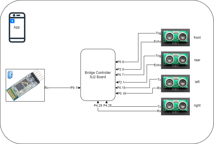
We employed a set of four Adafruit US-100 Ultrasonic Range Finders as sensory components in our project. These ultrasonic sensors were integrated into the RC car system with the objective of enabling effective obstacle avoidance. To achieve this, we strategically positioned three sensors on the front side of the RC car, while the remaining sensor was placed at the rear. The sensors were powered by a +5V supply voltage. An indicative sign of successful data retrieval was the toggling of LED3 on the SJ2 board.
The operational principle is as follows: When the trigger pin is set to a HIGH state for a minimum duration of 10 microseconds, the module automatically emits a 40 kHz ultrasonic wave from the Ultrasonic transmitter. This wave propagates through the air and, upon encountering an obstruction, it reflects back towards the sensor. The Ultrasonic receiver module detects this reflected wave. As soon as the wave returns, the Echo pin becomes HIGH for a specific duration, equivalent to the time it took for the wave to travel back to the sensor.
for UART: To establish communication with the sensor, a UART baud rate of 9600 is utilized. In UART mode, a command is sent by transmitting the hexadecimal value 0x55 to the sensor. Following the command transmission, two bytes (a 16-bit value) are read back, representing the distance in millimeters (mm).
The SJ2 board measures the length of time during which the Echo pin remains HIGH, providing information about the duration of the wave's round trip. Utilizing this information, the distance is calculated, as described in the previous section. The formula used to measure the distance to the object is Distance = Speed × Time, where the speed represents the speed of sound.
Software Design
Among these sensors, two employed UART communication to transmit distance data to the SJ2 microcontroller, whereas the other two utilized interrupt-based communication. To facilitate communication with the SJ2 microcontroller, UART1 and UART3 were designated for the right and left sensors, respectively. Additionally, pins P0.6 and P0.7 were allocated as trigger pins, while pins P2.0 and P2.1 served as echo pins for the front and rear sensors.
Sensors were divided into two groups:
- Front and Rear
- Left and Right
Each group utilizes a frequency of 10Hz. The provided code demonstrates its periodic invocation.
void periodic_callbacks__10Hz(uint32_t callback_count) {
  get_sonar_values();
  if ((ultrasonic_can_tx()) && (car_heartbeat_tx_10hz()) && (destination_coordinate_tx_10hz())) {
    gpio__toggle(board_io__get_led3());
  }
The following code snippet demonstrates the initialization of the triggers for the front and rear sensors in 100Hz.
void periodic_callbacks__100Hz(uint32_t callback_count) {
ultrasonic_implementation__initiate_ultrasonics_range();
}
Technical Challenges
- Issue: The presence of noise in the sensor measurements is causing instability in the car's steering, resulting in a wobbly motion.
- Solution: To address the issue of noise in the sensor measurements and stabilize the car's steering, we have implemented an average buffer. This buffer calculates the average value based on the last 10 readings rather than relying on a single value. By taking into account multiple readings over a period of time, the average buffer helps to reduce the impact of noise and provide a more stable steering response for the car.
Motor ECU
<Picture and link to Gitlab>
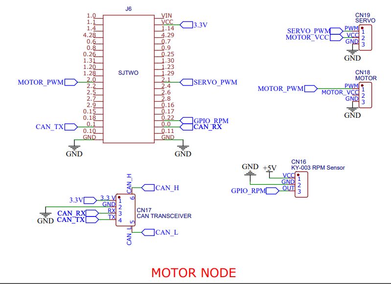
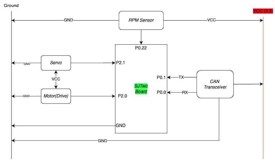
The primary function of this module involves establishing a communication interface with the Driver Node, employing the CAN (Controller Area Network) communication protocol. Through this communication protocol, the module receives and retrieves the desired speed and steering angle information from the Driver Node. The CAN protocol facilitates the exchange of data between the module and the Driver Node, enabling seamless transmission of control signals for speed and steering angle adjustments.
Motors work on the PWM (pulse width modulation) values which are given by the ESC. ESCs process input signals, convert them into digital values, use algorithms to determine motor speed, generate PWM signals with variable pulse width, calculate duty cycle, and drive motors through power transistors to control speed. Understanding these PWM values for motor movements is a critical task which has to be done when we start working on the project.
Hardware Design
Hacking the RF Module
In order to make the RC car autonomous, we had to get rid of the remote control that the car is equipped with. Our car - Maverick Quantum MT does not have its PWM sequence open-sourced. So, we had to get our hands dirty in detecting the PWM signals sent by the RC receiver to the ESC module. Using an oscilloscope / logic analyzer. (We mostly preferred the logic analyzer considering the ease to operate and options the software provides to read the signals obtained), we could identify the duty cycle and frequency corresponding to the servo and motor actions.
| Control Unit | Direction | Frequency (Hz) | Duty Cycle (%) |
|---|---|---|---|
| Servo Motor | Right Max | 61.02 | 5.9 |
| Left Max | 61.02 | 12.62 | |
| Motor | Forward Max Speed | 61.02 | 12.65 |
| Idling (Zero) Speed | 61.02 | 9.27 | |
| Reverse Max Speed | 61.02 | 5.66 |
The duty cycle for crawling the car at the slowest speed = 9.47%.
Software Design
<List the code modules that are being called periodically.>
Technical Challenges
< List of problems and their detailed resolutions>
Geographical Controller
<Picture and link to Gitlab>
Hardware Design
Software Design
<List the code modules that are being called periodically.>
Technical Challenges
< List of problems and their detailed resolutions>
Communication Bridge Controller & LCD
<Picture and link to Gitlab>
Hardware Design
Software Design
<List the code modules that are being called periodically.>
Technical Challenges
< List of problems and their detailed resolutions>
Master Module
<Picture and link to Gitlab>
Hardware Design
Software Design
<List the code modules that are being called periodically.>
Technical Challenges
< List of problems and their detailed resolutions>
Mobile Application
<Picture and link to Gitlab>
Hardware Design
Software Design
<List the code modules that are being called periodically.>
Technical Challenges
< List of problems and their detailed resolutions>
Conclusion
<Organized summary of the project>
<What did you learn?>
Project Video
Project Source Code
Advise for Future Students
<Bullet points and discussion>
Acknowledgement
=== References ===


