S23: Meh-sla Automotive
Contents
Project Title
<Team Name>
Abstract
<2-3 sentence abstract>
Introduction
The project was divided into N modules:
- Sensor ...
- Motor..
- ...
- Android
Team Members & Responsibilities
<Team Picture>
Gitlab Project Link - [1]
<Provide ECU names and members responsible> <One member may participate in more than one ECU>
- Sensor
- Link to Gitlab user1
- Link to Gitlab user2
- Motor
- Link to Gitlab user1
- Link to Gitlab user2
- Geographical
- Link to Gitlab user1
- Link to Gitlab user2
- Communication Bridge Controller & LCD
- Link to Gitlab user1
- Link to Gitlab user2
- Android Application
- Link to Gitlab user1
- Link to Gitlab user2
- Testing Team
- Link to Gitlab user1
- Link to Gitlab user2
Schedule
| Week # | Start Date | End Date | Task | Status |
|---|---|---|---|---|
| 1 | 2/12/2023 | 2/18/2023 |
|
|
| 2 | 2/19/2023 | 2/25/2023 |
|
|
| 3 | 26/2/2023 | 3/4/2023 |
|
|
| 4 | 3/5/2023 | 3/11/2023 |
|
|
| 5 | 3/12/2023 | 3/18/2023 |
|
|
| 6 | 3/19/2023 | 3/25/2023 |
|
|
| 7 | 3/26/2023 | 4/1/2023 |
|
|
| 8 | 4/2/2023 | 4/8/2023 |
|
|
| 9 | 4/9/2023 | 4/15/2023 |
|
|
| 10 | 4/16/2023 | 4/22/2023 |
|
|
| 11 | 4/23/2023 | 4/29/2023 |
|
|
| 12 | 4/30/2023 | 5/6/2023 |
|
|
| 13 | 5/7/2023 | 5/13/2023 |
|
|
| 14 | 5/14/2023 | 5/19/2023 |
|
|
Parts List & Cost
| Item# | Part Desciption | Vendor | Qty | Cost |
|---|---|---|---|---|
| 1 | RC Car | Traxxas | 1 | $250.00 |
| 2 | CAN Transceivers MCP2551-I/P | Microchip [2] | 8 | Free Samples |
Printed Circuit Board
<Picture and information, including links to your PCB>
CAN Communication
<Talk about your message IDs or communication strategy, such as periodic transmission, MIA management etc.>
Hardware Design
<Show your CAN bus hardware design>
DBC File
VERSION ""

NS_ :
	BA_
	BA_DEF_
	BA_DEF_DEF_
	BA_DEF_DEF_REL_
	BA_DEF_REL_
	BA_DEF_SGTYPE_
	BA_REL_
	BA_SGTYPE_
	BO_TX_BU_
	BU_BO_REL_
	BU_EV_REL_
	BU_SG_REL_
	CAT_
	CAT_DEF_
	CM_
	ENVVAR_DATA_
	EV_DATA_
	FILTER
	NS_DESC_
	SGTYPE_
	SGTYPE_VAL_
	SG_MUL_VAL_
	SIGTYPE_VALTYPE_
	SIG_GROUP_
	SIG_TYPE_REF_
	SIG_VALTYPE_
	VAL_
	VAL_TABLE_

BS_:

BU_: DBG DRIVER MOTOR SENSOR GEO

BO_ 100 DRIVER_HEARTBEAT: 1 DRIVER
 SG_ DRIVER_HEARTBEAT_cmd : 0|8@1+ (1,0) [0|0] "" SENSOR,MOTOR

BO_ 101 MOTOR_SPEED: 1 DRIVER
 SG_ DC_MOTOR_DRIVE_SPEED_sig : 0|8@1+ (0.1,-10) [-10|10] "kph" MOTOR

BO_ 102 MOTOR_ANGLE: 1 DRIVER
 SG_ SERVO_STEER_ANGLE_sig : 0|8@1+ (1,-45) [-45|45] "degrees" MOTOR


BO_ 200 SENSOR_SONARS: 4 SENSOR
 SG_ SENSOR_SONARS_left : 0|8@1+ (1,0) [0|158] "inch" DRIVER
 SG_ SENSOR_SONARS_right : 8|8@1+ (1,0) [0|158] "inch" DRIVER
 SG_ SENSOR_SONARS_front : 16|8@1+ (1,0) [0|158] "inch" DRIVER
 SG_ SENSOR_SONARS_rear : 24|8@1+ (1,0) [0|158] "inch" DRIVER

BO_ 202 GPS_DESTINATION_LOCATION: 8 SENSOR
 SG_ GPS_DEST_LAT_SCALED_1000000 : 0|32@1- (1,0) [0|0] "Degrees" GEO
 SG_ GPS_DEST_LONG_SCALED_1000000 : 32|32@1- (1,0) [0|0] "Degrees" GEO

BO_ 203 GEO_STATUS: 8 GEO
 SG_ GEO_STATUS_COMPASS_HEADING : 0|12@1+ (0.1,0) [0|359.9] "Degrees" DRIVER,SENSOR
 SG_ GEO_STATUS_COMPASS_BEARING: 12|12@1+ (0.1,0) [0|359.9] "Degrees" DRIVER,SENSOR
 SG_ GEO_STATUS_DISTANCE_TO_DESTINATION : 24|16@1+ (0.01,0) [0|0] "Meters" DRIVER,SENSOR

BO_ 204 GPS_CURRENT_INFO: 8 GEO
 SG_ GPS_CURRENT_LAT_SCALED_1000000 : 0|32@1- (1,0) [0|0] "degrees" DRIVER,SENSOR,MOTOR
 SG_ GPS_CURRENT_LONG_SCALED_1000000 : 32|32@1- (1,0) [0|0] "degrees" DRIVER,SENSOR,MOTOR

BO_ 205 GPS_CURRENT_DESTINATIONS_DATA: 8 GEO
 SG_ CURRENT_DEST_LAT_SCALED_1000000 : 0|32@1- (1,0) [0|0] "Degrees" DRIVER
 SG_ CURRENT_DEST_LONG_SCALED_1000000 : 32|32@1- (1,0) [0|0] "Degrees" DRIVER

BO_ 206 BRIDGE_APP_COMMANDS: 1 SENSOR
 SG_ APP_COMMAND : 0|2@1+ (1,0) [0|0] "" GEO,DRIVER

BO_ 300 MOTOR_STATUS: 3 MOTOR
 SG_ MOTOR_STATUS_wheel_error : 0|1@1+ (1,0) [0|0] "" DRIVER,IO
 SG_ MOTOR_STATUS_speed_kph : 8|16@1+ (0.001,0) [0|0] "kph" DRIVER,IO

BO_ 401 MOTOR_DEBUG: 1 MOTOR
 SG_ IO_DEBUG_test_unsigned : 0|8@1+ (1,0) [0|256] "sec" DBG

CM_ BU_ DBG "The debugging node for testing dbc with the car";
CM_ BU_ DRIVER "The driver controller driving the car";
CM_ BU_ MOTOR "The motor controller of the car";
CM_ BU_ SENSOR "The sensor controller of the car";
CM_ BU_ GEO "The geological Controller of the car";
CM_ BO_ 100 "Sync message used to synchronize the controllers";
CM_ SG_ 100 DRIVER_HEARTBEAT_cmd "Heartbeat command from the driver";
CM_ SG_ 101 DC_MOTOR_DRIVE_SPEED_sig "The speed in kph to set the motor speed. TODO: choose kph/mph";
CM_ SG_ 102 SERVO_STEER_ANGLE_sig "The direction in degrees to set the RC car servo direction.";

BA_DEF_ "BusType" STRING ;
BA_DEF_ BO_ "GenMsgCycleTime" INT 0 0;
BA_DEF_ SG_ "FieldType" STRING ;

BA_DEF_DEF_ "BusType" "CAN";
BA_DEF_DEF_ "FieldType" "";
BA_DEF_DEF_ "GenMsgCycleTime" 0;

BA_ "GenMsgCycleTime" BO_ 100 1000;
BA_ "GenMsgCycleTime" BO_ 200 50;
BA_ "FieldType" SG_ 100 DRIVER_HEARTBEAT_cmd "DRIVER_HEARTBEAT_cmd";

VAL_ 100 DRIVER_HEARTBEAT_cmd 2 "DRIVER_HEARTBEAT_cmd_REBOOT" 1 "DRIVER_HEARTBEAT_cmd_SYNC" 0 "DRIVER_HEARTBEAT_cmd_NOOP" ;
Sensor and Bridge Controller
Hardware Design - Ultrasonic Sensors
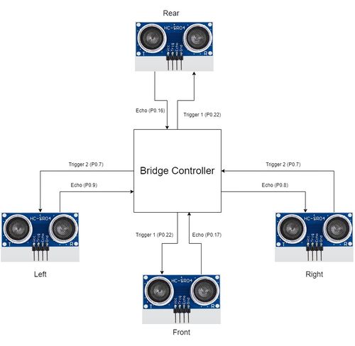
We used HC-SR04 ultrasonic sensors for obstacle detection. It could provide a range from 2 cm to 400 cm non-contact measurement. The ranging accuracy is approximately 3mm and the effectual angle is less than 15°. It needs to be powered by a 5V power supply.
HC-SR04 specifications and dimensions
- Working Voltage: DC 5V
- Working Current: 15mA
- Working Frequency: 40Hz
- Max Range: 4m
- Min Range: 2cm
- Measuring Angle: 15 degree
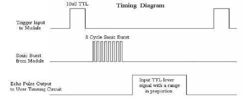
- Trigger Input Signal: 10µS TTL pulse
- Echo Output Signal Input TTL lever signal and the range in proportion
- Dimensions: 45 * 20 * 15mm
The pinout and the timing diagram of the HC-SR04 sensor is shown the following figures.
Software Design - Ultrasonic Sensors
<List the code modules that are being called periodically.>
Technical Challenges
< List of problems and their detailed resolutions>
Motor ECU
<Picture and link to Gitlab>
Hardware Design
Software Design
<List the code modules that are being called periodically.>
Technical Challenges
< List of problems and their detailed resolutions>
Geographical Controller
<Picture and link to Gitlab>
Hardware Design
Software Design
<List the code modules that are being called periodically.>
Technical Challenges
< List of problems and their detailed resolutions>
Communication Bridge Controller & LCD
<Picture and link to Gitlab>
Hardware Design
Software Design
<List the code modules that are being called periodically.>
Technical Challenges
< List of problems and their detailed resolutions>
Master Module
<Picture and link to Gitlab>
Hardware Design
Software Design
<List the code modules that are being called periodically.>
Technical Challenges
< List of problems and their detailed resolutions>
Mobile Application
<Picture and link to Gitlab>
Hardware Design
Software Design
<List the code modules that are being called periodically.>
Technical Challenges
< List of problems and their detailed resolutions>
Conclusion
<Organized summary of the project>
<What did you learn?>
Project Video
Project Source Code
Advise for Future Students
<Bullet points and discussion>
Acknowledgement
=== References ===


