F22: DDRTOS
Contents
Grading Criteria
- How well is Software & Hardware Design described?
- How well can this report be used to reproduce this project?
- Code Quality
- Overall Report Quality:
- Software Block Diagrams
- Hardware Block Diagrams
- Schematic Quality
- Quality of technical challenges and solutions adopted.
Abstract
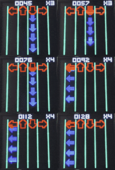
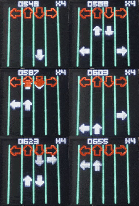
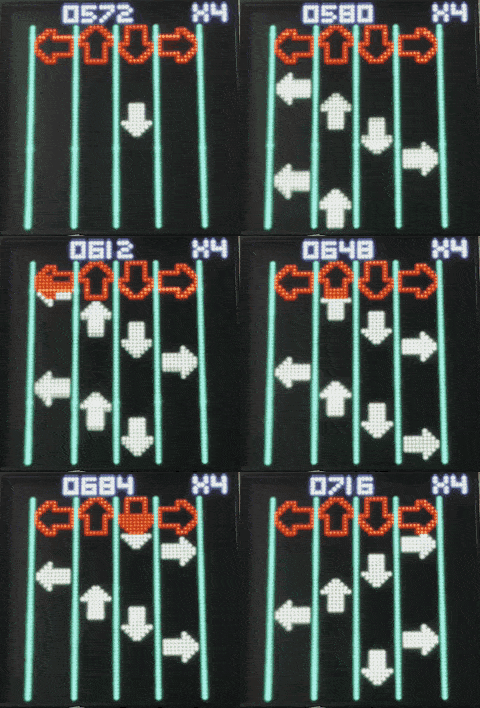
Rhythm games have been popular for years and date back to the 1970’s, but hit its stride in 1997 when one of the most notable and popular games released - Dance Dance Revolution (DDR). The main point of a rhythm game is to use music and challenge a player’s ability to stay on beat and typically press a button to the beat of the song. Our project is based and dedicated to DDR, as we all share a passion for music and video games. DDR is played with four arrows for each direction up, down, left, and right that need to be hit at the time of a beat in order to score and increase the multiplier. There are several aspects that are taken from other games like Guitar Hero and Friday Night Funkin’ (sound effects, multiplier, and artwork) that have also become a part of the project. Our project name, DDRTOS, is a combination of the game DDR and RTOS which runs the project.
Objectives & Introduction
Show list of your objectives. This section includes the high level details of your project. You can write about the various sensors or peripherals you used to get your project completed.
Team Members & Responsibilities
- Michael Hatzikokolakis
- Core gameplay development
- Beatmap development
- Kyle Kwong
- MP3 module driver development
- Audio system research and design
- Ensure coding standards
- Assist on all parts of the project
- Anthony Zunino
- Enclosure Design
- PCB Design
- Converted the mp3 module to use UART queue instead of polling
Schedule
| Week# | Start Date | End Date | Task | Status |
|---|---|---|---|---|
| 1 |
|
|
|
|
| 2 |
|
|
|
|
| 3 |
|
|
|
|
| 4 |
|
|
|
|
| 5 |
|
|
|
|
| 6 |
|
|
|
|
| 7 |
|
|
|
|
| 8 |
|
|
|
|
| 9 |
|
|
|
|
| 10 |
|
|
|
|
Parts List & Cost
Note: For the keycaps, we suggest using uniform profile keycaps such as DSA or XDA.
| Item# | Part Desciption | Vendor | Qty | Cost/Item |
|---|---|---|---|---|
| 1 | 64x64 RGB LED Matrix - 3mm Pitch (192mm x 192mm) | Adafruit [1] | 1 | $59.95 |
| 2 | MP3 Module | Amazon [2] | 1 | $12.99 |
| 3 | PCB | JLCPCB [3] | 1 | $ |
| 4 | NeoKey Socket Breakout for Mechanical Key Switches with NeoPixel – For MX Compatible Switches | Adafruit [4] | 4 | $1.75 |
| 5 | LM7805 Power Regulator | Digi-Key [5] | 1 | $0.75 |
| 6 | 10-pin Terminal Block | Digi-Key [6] | 1 | $3.86 |
| 7 | LEDs | Adafruit [7] | 8 | $5.00 |
| 8 | Mx style switches | Prevail [8] | 4 | $20.00 |
| 9 | Mx style keycaps | Adafruit [9] | 4 | $4.95 |
| 10 | SeeedStudio 4-pin connectors | SeedStudio [10] | 2 | $1.70 |
| 11 | 4-pin to wire connector cable | SeedStudio [11] | 2 | $3.20 |
| 12 | 20-pin ribbon cable | Adafruit [12] | 1 | $1.95 |
| 13 | Miscellaneous resistors and capacitors | N/A | N/A | N/A |
Design & Implementation
The design section can go over your hardware and software design. Organize this section using sub-sections that go over your design and implementation.
Hardware Design
- PCB
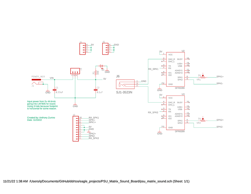
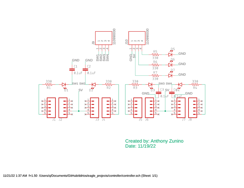
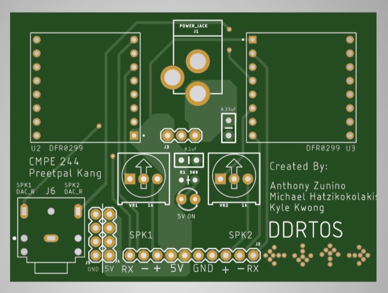
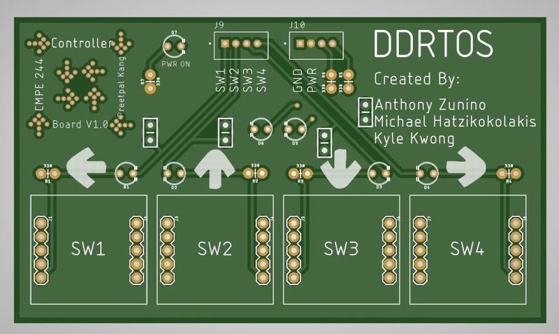
Creation of the PCBs were the highest priority at the start of the project in order to begin development and integration with the entire system. The original idea was to create a single master PCB, but evolved into two boards; one board will be used as the PSU and sound wiring for the SJ2 and LED Matrix, and the other board as a controller for the game both of which including LEDs indicating power, descriptive silkscreen, and easter eggs for DDR.
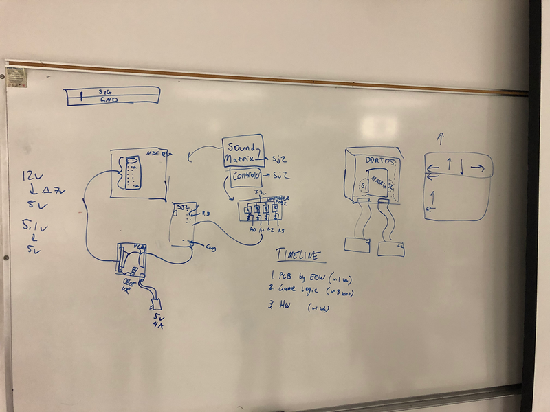
- Original brainstorm idea for PCBs and Enclosure and Timeline
- Schematic for the PSU
- Schematic for the controller - note that there is a minor error with the switch inputs tied directly to GND and the caps messed up the LEDs
- PSU, sound, and LED Matrix power PCB containing two MP3 decoders for multiple sound effects which port to an AUX output, extra 5V/GND pins, a power jack and 5V voltage regulator, and a neat DDR design.
- The controller PCB which takes in 5V and GND, and outputs four GPIO switch inputs using SeeedStudio 4-pin connectors.
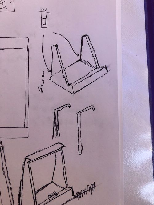
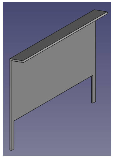
- 3D Printed Enclosure
Originally, the enclosure’s design was meant to replicate that of an old stand-up retro video game machine. As the design progressed, we wanted to go with a smaller version of the retro machine that was angled and provided both access to the PSU and SJ2 boards in the back while also maintaining a small form factor.
- Some original drawing ideas for the base of the enclosure, the enclosure drawing can be seen on the left, and backplate cover in the middle. What is not shown are the pages of mistakes, bad drawings, and measurements down to the 0.01mm for 3D printing.
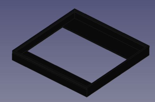
- The enclosure, with a slot for a piece of plastic to slide through and keep the LED Matrix from falling out. The opening in the back allows access to the power and ribbon-cable connections to the matrix
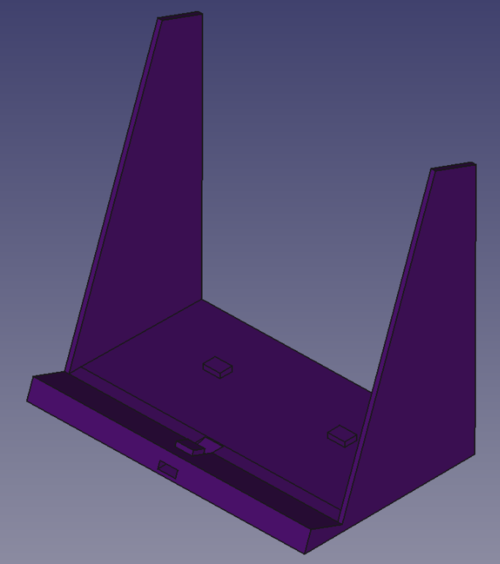
- The base which the enclosure connects to with the little tab on the slanted holder. The tabs in the back allow the PSU and SJ2 cases to connect and not jostle around
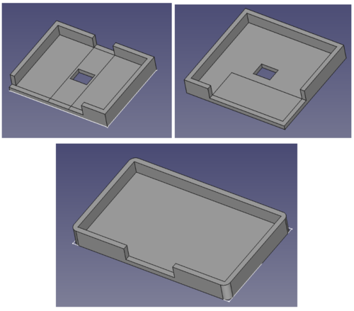
- The PSU, SJ2, and Controller cases from top-left to top-right to bottom. The openings allow access to the terminal block, power jack, micro-USB on SJ2, and the connectors on the controller.
- The backplate cover for the base. No connections except some material to make hot-gluing to the base easier.
In order to reproduce the enclosure, use the attached FreeCAD file in ddrtos/enclosure_cad to create .stl files for each part, or use the .stls saved in the ddrtos GitLab repo. Then use a slicer like Cura to generate G-code to upload to a 3D printer.
In order to reproduce the PCBs, take the gerber files located in the ddrtos/eagle_projects/controller and ddrtos/eagle_projects/PSU_Matrix_Sound_Board directories and go to pcbway.com to quote the boards. They take about 10 days (including weekends) to come in.
- Mechanical Keyboard Switches, Keycaps, and Breakout Board
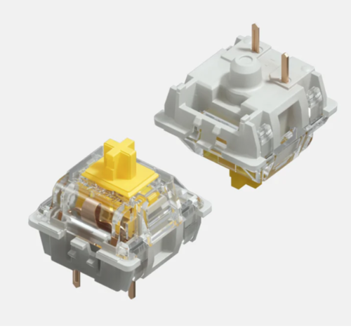
Mechanical switches usually have one to three plastic pins for stabilizing on the PCB. However, those pins also made it would be nearly impossible to use them on a breadboard during early development. As a result, we used the Neokey breakout boards. The breakouts were solely used for the alignment of the yellow switch as seen below:
- Top and bottom view of the yellow switches used as switch inputs for the game
The two pins on the bottom side and stabilizing pin made making a PCB footprint for the switch difficult, so a breakout board with standard 0.1” spacing was much easier, just a little more expensive. There is an open source library for MX style footprint for KiCad, however, because Eagle does not have support for library conversion, we were not able to take advantage of the library, and as a result, decided to use the breakout board for the PCB design.
As for keycaps, we chose DSA keycaps because Kyle thinks that for a flat controller design, uniform profile keycaps would provide the most comfort.
- Power
- Power bricks come in many different wattages and ratings, so a power jack and voltage regulator were the easiest solution to accommodate different power bricks while still providing a stable voltage for both the LED Matrix, SJ2 board, and controller. The traces on each of the PCBs were widened as much as possible to allow as much current to flow as needed, and the wires and terminal block connections were selected based on the specifications of the Matrix as it was the biggest power draw.
Hardware Interface
In this section, you can describe how your hardware communicates, such as which BUSes used. You can discuss your driver implementation here, such that the Software Design section is isolated to talk about high level workings rather than inner working of your project.
- DFmini MP3 Module
- The MP3 module uses UART to receive instructions from SJ2, with a baud rate of 9600.
- You can select the playback source by sending it the select playback device instruction (0x09). We chose SD card (parameter 0x0002) as our playback source because it requires the least amount of signal processing.
- The module is able to play from 0001.mp3 up to 2999.mp3.
Software Design
Show your software design. For example, if you are designing an MP3 Player, show the tasks that you are using, and what they are doing at a high level. Do not show the details of the code. For example, do not show exact code, but you may show psuedocode and fragments of code. Keep in mind that you are showing DESIGN of your software, not the inner workings of it.
Implementation
This section includes implementation, but again, not the details, just the high level. For example, you can list the steps it takes to communicate over a sensor, or the steps needed to write a page of memory onto SPI Flash. You can include sub-sections for each of your component implementation.
-
mp3_module.c- The driver has 5 public functions.
- We dedicated one pin for each UART port
-
void mp3_module__init(uart_e uart_to_use);- This function sets the dedicated pin for the selected UART port to UART mode, initializes the UART, and selects SD card as the playback source. If the GENUINE macro is set to 1, it also sets the volume to 10.
-
void mp3_module__play(uart_e uart_to_use, uint32_t song_number);- This function sends the instruction to the mp3 module to play the song with the name song_number.mp3. It checks to make sure that the song_number is less than or equal to 2999.
-
void mp3_module__resume(uart_e uart_to_use);- This function resumes a paused song.
-
void mp3_module__pause(uart_e uart_to_use);- This function pauses a playing song.
-
void mp3_module__reset_playback(uart_e uart_to_use);- This function resets the module.
| UART Port | UART_0 | UART_1 | UART_2 | UART_3 |
|---|---|---|---|---|
| GPIO Port.Pin | 0.0 | 2.0 | 0.10 | 4.28 |
Testing & Technical Challenges
Describe the challenges of your project. What advise would you give yourself or someone else if your project can be started from scratch again? Make a smooth transition to testing section and described what it took to test your project.
Include sub-sections that list out a problem and solution, such as:
<Bug/issue name>
Discuss the issue and resolution.
Conclusion
Overall, the project was all encompassing of the topics learned over the semester; from binary semaphores and queues to interrupts to quick handlers, each and every lecture contributed to different parts of the project. There were difficulties in implementing all the tasks in a structured way in the beginning, but, as more code was modularized, a new structure to the codebase was developed to integrate each part of the project - for example, a sound effect could play from the mp3 module which is defined in the drivers layer, and it could be called quickly using a helper function defined in the top game logic layer. This helper is in an interrupt handler that was called by an ISR from a button rising-edge interrupt defined in the buttons module. Having this level of modularity made future implementation and additions quick and well-defined for readability. If things could have been done differently, ordering of all the parts and a very rough idea for how the entire game would progress would have saved a lot of time spent waiting for parts and with initial implementation. If there were more time to work on this project, more work could be added to the state machine to flesh out the game, as a lot of design went into the state machine near the demo deadline. Then, additional features like a high score system are easier to add and create a much more fun and competitive game. Overall, the project helped solidify the concepts learned in CMPE244 and development of the game was much more interesting since the solutions were all based on the background solidified in the first section of the course. There is no limit to what FreeRTOS can do besides the stack, CPU, and mental utilization!
Project Video
Project Source Code
References
Acknowledgement
Any acknowledgement that you may wish to provide can be included here.
References Used
Appendix
You can list the references you used.


