S22: TBD
Contents
Project Title
THE BEST DRIVER
Abstract
Our goal for this project is to use knowledge we gathered from lectures to design, implement, and test a self-driving RC car using a Controller Area Network (CAN) bus for controller communication. The project involves FreeRTOS and utilizes periodic tasks (running at 1Hz, 10Hz, and 100Hz) to gather, process, and display data from various embedded modules.
Introduction
The project was divided into 5 modules:
- Sensor/Bridge Controller
- Motor Controller
- Geo Controller
- Driver/LCD Controller
- Web Application
Team Members & Responsibilities
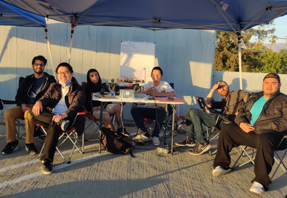
From Left to Right: Jasdip Sekhon, Brian Ho, Justin Stokes, Billy Lai, Isaac Wahhab, William Hernandez
- Sensor
- Jasdip Sekhon
- Brian Ho
- Justin Stokes
- Motor
- Justin Stokes
- Isaac Wahhab
- Geographical
- Brian Ho
- William Hernandez
- Jasdip Sekhon
- Driver Logic & LCD & LED Ring
- William Hernandez
- Billy Lai
- Isaac Wahhab
- Web Application & Communication Bridge Controller
- Isaac Wahhab
- Billy Lai
- Testing Team
- The Best Driver Team
Schedule
| Week# | Start Date | End Date | Task | Status |
|---|---|---|---|---|
| 1 | 02/15/2022 | 02/21/2022 |
|
Completed |
| 2 | 02/22/2022 | 02/28/2022 |
|
Completed |
| 3 | 03/01/2022 | 03/07/2022 |
|
Completed |
| 4 | 03/08/2022 | 03/14/2022 |
|
Completed |
| 5 | 03/15/2022 | 03/21/2022 |
|
Completed |
| 6 | 03/22/2022 | 03/28/2022 |
|
Completed |
| 7 | 03/29/2022 | 04/04/2022 |
|
Completed |
| 8 | 04/05/2022 | 04/11/2022 |
|
Completed |
| 9 | 04/12/2022 | 04/18/2022 |
|
Completed |
| 10 | 04/19/2022 | 04/25/2022 |
|
Completed |
| 11 | 04/26/2022 | 05/02/2022 |
|
Completed |
| 12 | 05/03/2022 | 05/09/2022 |
|
Completed |
| 13 | 05/10/2022 | 05/16/2022 |
|
Completed |
| 14 | 05/17/2022 | 05/25/2022 |
|
Completed |
Parts List & Cost
| Item# | Part Desciption | Vendor | Qty | Cost |
|---|---|---|---|---|
| 1 | RC Car | Redcat Racing | 1 | $139.00 |
| 2 | SJTwo Boards | SJTwo Boards On Amazon | 4 | $200.00 |
| 3 | CAN Transceivers (SN65HVD230) | Waveshare | 4 | $40.00 |
| 4 | LSM303 Triple-Axis Accelerometer and Magnetometer | Adafruit | 1 | $15.00 |
| 5 | Venus GPS with SMA Connector | SparkFun | 1 | |
| 6 | URM09 Ultrasonic Sensors | DFRobot Gravity | 4 | $52.00 |
| 7 | PCB | JLCPCB | 1 | $5.00 |
| 8 | Plexiglass | 1 | ||
| 9 | LCD Display | SunFounder LCD Display | 1 | $12.99 |
| 10 | APA102 Ring LED | Sparkfun | 1 | $11.50 |
| 11 | LEDs for obstacle detection, GPS lock status, and web app lock status | 6 | ||
| 12 | Rotary Encoder & Wheel Set | Tinkersphere | 2 | $10.99 |
| 13 | Set of Headlights and taillights | eBay | 1 | $3.99 |
| 14 | Logic Level Converters | Sparkfun | 1 | $3.50 |
| 15 | Buck Converters | 1 | ||
| 16 | Standoffs for mounting SJTwo boards, PCB, and raising compass | 40 |
Printed Circuit Board
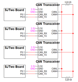
We designed and implemented two PCBs: CAN Bus PCB and RC Car PCB.
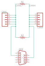
CAN Bus PCB Schematic
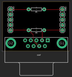
CAN Bus PCB Board
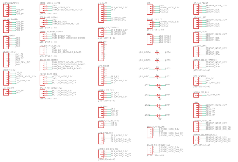
RC Car PCB Schematic
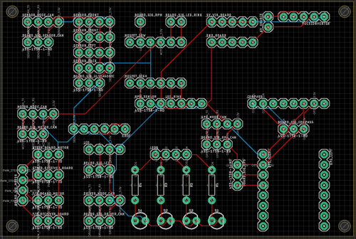
RC Car PCB Board
CAN Communication
Our message IDs are arranged with priority given to the nodes in the following order: DRIVER, SENSOR, GEO, MOTOR. The following critical messages are transmitted at 100Hz:
- SENSOR_TO_DRIVER_SONARS
- GPS_DESTINATION_LOCATION
- SENSOR_TO_DRIVER_WHEEL_ENCODER_MSG
- GEO_STATUS
- DRIVER_TO_MOTOR_CMD
The remaining debug messages are transmitted at 10Hz or 1Hz.
We decided to give 32 message IDs to each node and to separate the nodes' message IDs accordingly.
| Node | Message ID Range | |
|---|---|---|
| 1 | DRIVER | 32 - 63 |
| 2 | SENSOR | 63 - 95 |
| 3 | GEO | 96 - 127 |
| 4 | MOTOR | 128 - 159 |
Hardware Design
DBC File
Gitlab link to our master branch's DBC file
Our DBC file includes the SENSOR, DRIVER, MOTOR, and GEO nodes.
Below are the messages defined in the file:
BO_ 32 DRIVER_TO_MOTOR_CMD: 3 DRIVER
 SG_ DRIVER_TO_MOTOR_steer : 0|9@1+ (1,-180) [-180|179] "" MOTOR
 SG_ DRIVER_TO_MOTOR_speed : 9|5@1+ (1,0) [0|31] "RPM" MOTOR
 SG_ DRIVER_TO_MOTOR_current_rpm : 14|10@1+ (1,0) [0|1023] "RPM" MOTOR
BO_ 33 DRIVER_DEBUG_MSG: 1 DRIVER
 SG_ DRIVER_DEBUG_MSG_sensor_mia : 0|1@1+ (1,0) [0|0] "" DBG
 SG_ DRIVER_DEBUG_MSG_geo_mia : 1|1@1+ (1,0) [0|0] "" DBG
BO_ 64 SENSOR_TO_DRIVER_SONARS: 4 SENSOR
 SG_ SENSOR_TO_DRIVER_SONARS_front_left : 0|8@1+ (1,0) [0|0] "" DRIVER
 SG_ SENSOR_TO_DRIVER_SONARS_front_middle : 8|8@1+ (1,0) [0|0] "" DRIVER
 SG_ SENSOR_TO_DRIVER_SONARS_front_right : 16|8@1+ (1,0) [0|0] "" DRIVER
 SG_ SENSOR_TO_DRIVER_SONARS_back : 24|8@1+ (1,0) [0|0] "" DRIVER
BO_ 65 GPS_DESTINATION_LOCATION: 7 SENSOR
 SG_ GPS_DESTINATION_LOCATION_latitude : 0|28@1+ (0.000001,-134.217727) [-134.217727|134.217728] "" GEO,DRIVER
 SG_ GPS_DESTINATION_LOCATION_longitude : 28|28@1+ (0.000001,-134.217727) [-134.217728|134.217728] "" GEO,DRIVER
BO_ 66 SENSOR_TO_DRIVER_WHEEL_ENCODER_MSG: 2 SENSOR
 SG_ SENSOR_TO_DRIVER_WHEEL_ENCODER_MSG_rpm : 0|10@1+ (1,0) [0|0] "RPM" DRIVER,DBG
BO_ 67 SENSOR_TO_DRIVER_APP_CONNECTION_MSG: 1 SENSOR
 SG_ SENSOR_TO_DRIVER_APP_CONNECTION_MSG_app_connected : 0|1@1+ (1,0) [0|0] "" DRIVER
BO_ 96 GEO_STATUS: 5 GEO
  SG_ GEO_STATUS_compass_heading : 0|9@1+ (1,0) [0|359] "Degrees" SENSOR,DRIVER
  SG_ GEO_STATUS_destination_heading : 9|9@1+ (1,0) [0|359] "Degrees" SENSOR,DRIVER
  SG_ GEO_STATUS_distance_to_destination : 18|16@1+ (0.1,0) [0|0] "Meters" SENSOR,DRIVER
BO_ 97 GEO_DEBUG_MSG: 1 GEO
  SG_ GEO_DEBUG_MSG_lock_status : 0|1@1+ (1,0) [0|0] "" DRIVER,DBG
  SG_ GEO_DEBUG_MSG_num_satellites : 1|4@1+ (1,0) [0|15] "" DRIVER,DBG
BO_ 98 GEO_CURRENT_LOCATION_DEBUG: 7 GEO
  SG_ GEO_CURRENT_LOCATION_DEBUG_latitude : 0|28@1+ (0.000001,-134.217727) [-134.217727|134.217728] "" DRIVER,DBG
  SG_ GEO_CURRENT_LOCATION_DEBUG_longitude : 28|28@1+ (0.000001,-134.217727) [-134.217728|134.217728] "" DRIVER,DBG
BO_ 99 GEO_CURRENT_DESTINATION_LOCATION_DEBUG: 7 GEO
  SG_ GEO_CURRENT_DESTINATION_LOCATION_DEBUG_latitude : 0|28@1+ (0.000001,-134.217727) [-134.217727|134.217728] "" SENSOR,DBG
  SG_ GEO_CURRENT_DESTINATION_LOCATION_DEBUG_longitude : 28|28@1+ (0.000001,-134.217727) [-134.217728|134.217728] "" SENSOR,DBG
BO_ 128 MOTOR_DEBUG_MSG: 3 MOTOR
 SG_ MOTOR_DEBUG_MSG_echo_steer : 0|3@1+ (1,-2) [-2|2] "" DBG
 SG_ MOTOR_DEBUG_MSG_echo_speed : 3|5@1+ (1,0) [0|31] "RPM" DBG
 SG_ MOTOR_DEBUG_MSG_echo_rpm : 8|10@1+ (1,0) [0|1023] "RPM" DBG
MIA Management
Since the DRIVER node is our main controller, we conducted MIA management in the driver_logic code module.
Our MIA management is serviced at 10Hz and ensures that the expected messages are received within a time limit set by threshold values.
If a message goes "missing" past set threshold times, a default replacement value is used.
The MIA threshold values and replacement structures are found in the can_mia_configurations.c file.
SENSOR_TO_DRIVER_SONARS
- Default value in the DRIVER node is to set the sensor values to 0. This will result in the driver_logic simulating obstacles detected at 0cm in the front and back, and the car will not move.
GPS_DESTINATION_LOCATION
- Default value in the GEO node is to set the current coordinates and destination coordinates to 0. This will result in a 0 distance_to_destination calculation, and the DRIVER node will subsequently send an IDLE speed to the MOTOR node.
GEO_STATUS
- Default value in the DRIVER node is to set compass heading, destination heading, and distance to destination to 0. This will result in the ring LED not lighting up (to show an invalid state) and the DRIVER will send an IDLE speed to the MOTOR node.
DRIVER_TO_MOTOR_CMD
- Default value in the MOTOR node is to set the motor speed and steering to IDLE and 0, respectively. Without updated driver to motor commands, the RC car should not move.
Sensor Controller
Hardware Design
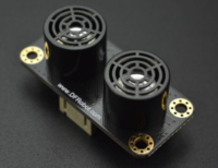
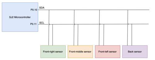
We used 4 Gravity DFRobot URM09 ultrasonic sensors. These ultrasonic sensors are used by the RC car for the purpose of obstacle avoidance. Three sensors were placed on the front side of the RC car and one on the back. They use I2C communication to send distance data to the SJ2 microcontroller. On the SJ2 microcontroller, P0.10 was used for SDA, and P0.11 was used for SCL. The measurement range is 300cm. It takes in 3.3V supply voltage. Using the I2C driver, the registers on the ultrasonic sensors were configured and the distance was read from the specified registers in the datasheet.
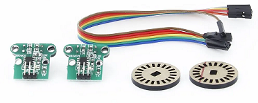
The wheel encoder is interfaced using 3 pins: VCC, GND, and OUT. The voltage input requires 4.5-5.5V and the data pin outputs 5V. The 5V output is converted to 3.3V using a level converter, and then used as a GPIO input to P0.22 on the SENSOR node.
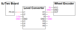
The rotary wheel has 20 slits spaced evenly. An infrared beam and sensor is used to detect when the beam is blocked. When the beam is blocked, the data OUT pin outputs 0V. When the beam is unblocked, the data OUT pin outputs 5V.
Software Design
The ultrasonic sensors use the I2C driver available in the project. The implementation is done in the 100Hz periodic callback function. After writing to the control register address of the ultrasonic sensors, the distance values are read from the appropriate distance. The sensors periodically send sound waves at different times. After the distance values were read, they were sent to the driver for obstacle avoidance.
Technical Challenges
1. Ultrasonic sensor interference
- Since we had 3 ultrasonic sensors on the front side sending sound waves, there was interference between them. As a result, the values being read from the sensors were incorrect. To resolve this issue, instead of sending sound waves at once from all the front sensors in the periodic callbacks function, we decided to send them at different times.
2. Ultrasonic sensor wiring not secure
- One of the issues we faced was that the sensors would not be connected properly because the RC car was constantly being moved around. A solution was to clean up the wiring and using a PCB. Also, we would use CAN Busmaster to check which sensors were not connected.
Motor Controller
Hardware Design
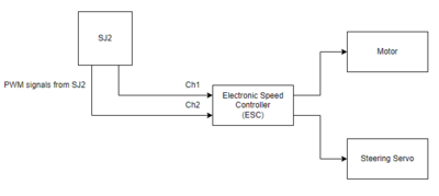
The hardware design for the motor controller was determined by the hardware of the car. We knew that the cars motors were controller through an electronic speed controller(ESC) and just had to interface the SJ2 with this. The top of the receiver revealed 12 pins, in 4 rows of 3. Each row had the following according the the sticker: GND, VCC, and signal. The signal pin would be hooked up to the pins which are firmware configured to output PWM.
Software Design
Controlling the motors was done through firmware generating PWM signals. We decided to begin by hooking up the car's receiver to a Saleae Logic Analyzer to see the waveforms generated when using the remote control that came with the car. This was helpful in many ways. First, we were able to see which channel was used for the steering servo, and which was used for the actual motor. Second, we were able to see the maximum, minimum, and neutral PWM duty cycles required and the period period of the waveform. Lastly, we were able to visually see the different sequences necessary to run the motors.
Technical Challenges
< List of problems and their detailed resolutions>
Geographical Controller
<Picture and link to Gitlab>
Hardware Design
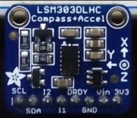
LSM303DLHC Magnetometer
For the compass heading we used the lsm303DLHC compass + accelerometer from Adafruit. The compass was interfaced using I2C with a speed of 100KHz. The data output rate was set to 220HZ. The gain was left as the default +-1.3 gauss. The operation mode was switch to continuous conversion mode. The compass was placed at a safe distance above all of the other hardware components to minimize the magnetic disturbance.
LSM303DLHC Compass+Accel
Software Design
Compass Implementation and Calibration
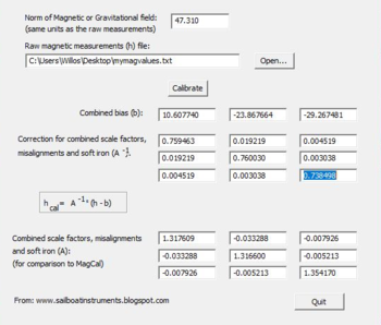
Once the required registers have been initialized, the compass will return uncalibrated x, y, and z values. For its calibration we used the software Magneto v1.2. Magneto requires a txt file of raw magnetometer values and our locations magnetic field. Magneto will then provide the bias and scaling factor matrix needed for calibration. Those values are then plug into the equation Matrix^-1((raw/gain*100)-bias), where gain is 1100 gauss for the x and y values and 980 gauss for the z value. Those calibrated x and y values are used to find the radians of the compass heading. The radians are then converted and returned as degrees. By flipping the compass upside down, the compass was able to reduced tilt factor to provide accurate readings.
Magneto1.2v Calibration
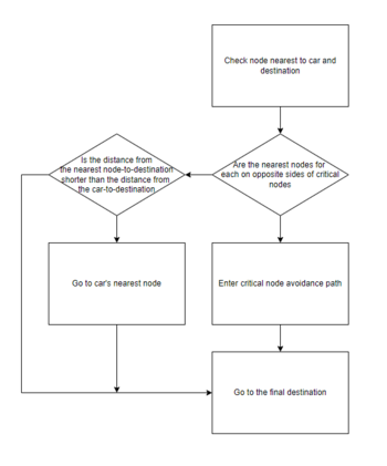
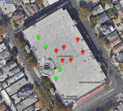
Waypoints Algorithm
Technical Challenges
1. Compass calibration
- Use magnetic field of current position
- Use Magneto software
2. Reliable compass readings
- Flip the compass upside down for more accurate readings
Driver Controller
Code for Driver Logic Debug Menu State Machine for Menu Navigation
Code for LCD I2C Initialization and Configuration

Hardware Design
Software Design
Inside periodic_callbacks_DRIVER.c, driver_logic__manage_debug_menu_10hz is periodically called at 10Hz rate. The definition for this method is shown below:
 void driver_logic__manage_debug_menu_10hz(uint32_t callback_count) {
   display_debug_menu_on_lcd(callback_count);
   handle_debug_menu_navigation();
 }
This snippet of code is responsible for maintaining the LCD debug menu state machine. It periodically updates the LCD to display menu navigation screens or debug information.
Technical Challenges
1. LCD display is limited to 4 lines of 20 characters. Having this limit creates a challenge for efficiently using the screen for debugging.
- To resolve this issue, we designed and implemented a finite state machine to update the LCD display according to a debug menu state. This solution is beneficial for its scalability. New debug information can be easily included as additional options in the menu navigation.
2. I2C bus speed was configured too high
- We saw issues with the LCD screen resetting unexpectedly during testing. This was due to our I2C bus speed being configured to run at 400KHz. After reviewing the datasheet, we found that using 100KHz for the I2C bus speed is the correct configuration.
Master Module
<Picture and link to Gitlab>
Hardware Design
Software Design
<List the code modules that are being called periodically.>
Technical Challenges
< List of problems and their detailed resolutions>
Mobile Application
<Picture and link to Gitlab>
Hardware Design
Software Design
<List the code modules that are being called periodically.>
Technical Challenges
< List of problems and their detailed resolutions>
Conclusion
<Organized summary of the project>
<What did you learn?>
Project Video
Youtube Link <-- temporary video, will be updated
Project Source Code
Advice for Future Students
- Add a mobile kill-switch to stop the car
- The car may drive at high speeds and not behave as expected. It is helpful to be able to wirelessly stop the car.
- Add plenty of LED indicators on the RC car
- GPS lock, app connection, obstacle detection, destination reached, etc
- Turn off on-board LEDs for each controller at the end of periodic_callbacks__initialize(). The current base code will light the on-board LEDs in peripherals_init(). By turning off the LEDs after initialization, it will be convenient to use the LEDs to indicate whether the board is resetting unexpectedly
- Stabilize your compass readings
- Calibrate your compass
- Verify tilting the car will not drastically affect magnetometer readings
- Mount the compass module away from metals and any hard/soft iron that may cause the readings to be inaccurate
- Unit test code modules to verify expected behavior
- Once your car can move, test outside on the garage.
- Ultrasonic sensors give incorrect readings at steep angles, making testing in the hallway somewhat difficult.
- Compass readings are also more accurate outside the building where there is less interferance.
Acknowledgement
We would like to acknowledge our instructor, Preet, for encouraging us to gather knowledge and to tackle difficult problems.
References
1. Ultrasonic Sensor Project Wiki
2. GPGGA Message Definition
3. LSM303DLHC Datasheet
4. Venus638FLPx GPS Receiver Datasheet
5. LCD Display Initialization and Configuration Example Tutorial
6. APA102 Ring LED Datasheet
7. Logic Level Converter Datasheet
