F21: Flame Over
Contents
Abstract
Flame Over is a single-player mode game where the player moves a fire fighter to destroy the fire flames that come shooting at the player using a water gun. The player is granted four lives at the start of the game at each level. The Player’s lives will decrease by one for every three flames that touch the fire fighter. The player transits to the next level when enough flames are destroyed at each level. The speed of the flames approaching the fire fighter varies between levels.
Objectives & Introduction
Show list of your objectives. This section includes the high level details of your project. You can write about the various sensors or peripherals you used to get your project completed.
Objectives
- Write driver module to display game characters and update the display continuously at an optimum refresh rate
- Implement game algorithm for movement of player and flames in real-time, generate water splash bullets.
- Implement player lives count, player health and collision algorithms.
- Write driver module to receive directions from the input device (joystick) via zigbee.
- Fetch Joystick data over ADC and transmit the joystick signals wirelessly via Zigbee with the help of UART drivers.
- Write driver module to play game sounds via MP3 encoder
- Use FreeRTOS tasks and understand task priority and synchronization.
Team Members & Responsibilities
- Naveena Sura
- Game logic and design
- Game implementation
- Built game characters on LED matrix display
- Game Animation Screens
- Bug fixes and optimizations
- Suganya Nandakumar
- GPIO Driver for LED matrix display
- Built game characters on LED matrix display
- PCB Schematic and Board Design
- Soldering all components on PCB
- Vaidehi Deshpande
- Joystick Interfacing - ADC driver
- Speaker and MP3 Decoder interfacing
- Zigbee interfacing with UART driver for transmission and reception
- Built game characters on LED matrix display
Schedule
| Week# | Start Date | End Date | Task | Status |
|---|---|---|---|---|
| 1 |
|
|
|
|
| 2 |
|
|
|
|
| 3 |
|
|
|
|
| 4 |
|
|
|
|
| 5 |
|
|
|
|
| 6 |
|
|
|
|
| 7 |
|
|
|
|
| 8 |
|
|
|
|
| 9 |
|
|
|
|
Parts List & Cost
| Item# | Part Desciption | Vendor | Qty | Cost |
|---|---|---|---|---|
| 1 | SJTwo Boards | From Amazon | 2 | $100.00 |
| 2 | 64x64 RGB LED Matrix | Adafruit | 1 | $92.00 |
| 3 | Wiring Components and Cable | Amazon | 1 | $20 |
| 4 | Digi Xbee module | From Preet | 2 | $0 |
| 5 | HiLetGo Analog 2-axis thumb Joystick | Amazon | 1 | $9 |
| 6 | MP3 music player (YX5300) | Amazon | 1 | $8 |
| 7 | 5V,4A Power Adapter | Amazon | 1 | $20 |
Design & Implementation
The design section can go over your hardware and software design. Organize this section using sub-sections that go over your design and implementation.
Pin Configuration
-
Pin# SJ2 Main Board - LED Matrix Pin Configuration SJ-2 PIN R1 PIN for Red terminal of RGB LED for the upper half of LED Matrix P0_0 G1 PIN for Green terminal of RGB LED for the upper half of LED Matrix P0_1 B1 PIN for Blue terminal of RGB LED for the upper half of LED Matrix P2_2 R2 PIN for Red terminal of RGB LED for the lower half of LED Matrix P2_4 G2 PIN for Green terminal of RGB LED for the lower half of LED Matrix P2_5 B2 PIN for Blue terminal of RGB LED for the lower half of LED Matrix P2_6 A Mux pin for row selection P2_7 B Mux pin for row selection P2_8 C Mux pin for row selection P2_9 D Mux pin for row selection P0_16 E Mux pin for row selection P0_15 OE Output Enable P1_28 LATCH Data Latch P1_29 CLK Clock Signal P0_17 MP3 Decoder RX UART Receive From MP3 Decoder P2_1 TX UART Send Command from SJ-2 Main Board P2_0 XBEE Module Receiver RX UART Receive From Game Controller P0_11 VCC VCC Supply VCC 3.3 -
Pin# Controller Board Pin Configuration uC PIN XBEE Module Transmitter TX UART Transmit to Main Board P0_10 VCC VCC Supply VCC 3.3 Joystick VCC VCC 3.3V GND GND GND Vx X-axis ADC Reading for character movement P0_25 Push Button I/0 Pin Arrow Shooting P1_29
LED Matrix
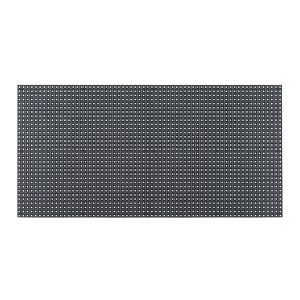
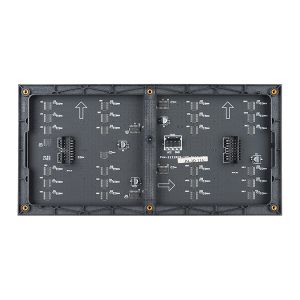
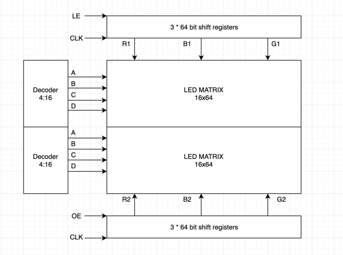
A 64x64 RGB LED Matrix Panel is used as a display. It has 64 rows and 64 columns. It is divided into two 32x64 sections. A LED or pixel (which we use in subsequent sections) can be accessed and controlled individually. A decoder is used to access individual row. One row can be selected at a time using A,B,C,D and E pins. This enables us to select one row in each of the 32X64 sections. Columns are controlled using shift registers, every bit in the shift register controls the corresponding column. On every falling edge of the clock pulse, the values at R1, B1, G1, R2, B2, and G2 pins are stored into the shift register and the register shifts the data by one bit. After this, the data on the shift register is passed onto the individual LED's when both OE and LE pins are set to high.
|
LED matrix pins:
|
Hardware Design
Software Design and Implementation
Start up screen:
Before the RTOS tasks are scheduled, startup_screen() is called. Animation is displayed until user presses the key to start the game.
Led Display and Task List:
There are six different tasks to control the course of the game:
- Refresh Display Task: This task has the following responsibilities
- Refreshes the screen every 3 milliseconds(involves clearing the screen and updating with latest values).
- Draws all the characters periodically every 3 milliseconds.
- Checks for level up
- Checks collision(Spaceship to Enemy collision, Spaceship to bullet collision, Bullet to Bullet collision) and updates the flags based on the collision type
- Update Spaceship Task: The task keeps track of the data coming wirelessly from the Bluetooth device connected to the board, and accordingly controls user spaceship position. It is designed support movement for all angles. This task also checks if shoot key is pressed and updates the flag if the key was pressed.
- Fire Task: It reads the shoot flag that has been updated in ‘Update Spaceship Task’ and controls the movement of bullet. This task calls PLAY_BULLET(macro to play respective game sound), if bullet hits an enemy.
- Enemy Task1 and Enemy Task2 : This task has the following responsibilities.
- Generates enemy characters on the upper and lower half of the display and move them till the end unless there is a collision. If there is a collision then the movement is stopped.
- These also generate random color and random row position for each of these characters.
- Manages user spaceship health decrement upon collision.
- PLAY_COLLISION() Macro call to play sound if there is collision
Collision detection:
There are two collision detection functions:
- Check Collision : This function detects the following collisions
- Bullet to Enemy Collision : The movement of bullet and enemy spaceship is stopped and both are cleared from the screen. Kill count is incremented for level up and respective flags are set. Burst animation is played at the collision spot.
- Spaceship to Enemy Collision : The movement of enemy spaceship is stopped and it is cleared from the screen. Respective flags are set and burst animation is played at the collision spot.
- Villian Collision : This function detects the following collisions
- Bullet to bullet collision : The movement of both the bullets are stopped and both are cleared from the screen.
- Spaceship to villain bullet collision : The movement of bullet is stopped and it is cleared from the screen. Health of the user spaceship is decremented.
Printed Circuit Board
Layout & Design
MP3 Serial Player:
MP3 Serial Player module is a simple MP3 player device which is based on a high quality MP3 audio chip. It can support 8kHz - 48kHz sampling frequency MP3 and WAV file formats. Also, this board has a TF card socket so that a SD card can be inserted that stores audio files. SJTwo board can control this module via UART port, such as switch songs, change the volume and play mode, and so on.
The SD card should be formatted as FAT16 or FAT32 and should have some audio files with .mp3 or .wav formats. If user wants to create separate folders then those should be created as “01”, “02” and the songs should be with the names 001xxx.mp3/ 002xxx.mp3/ 003xxx.mp3 in those created folders.
Hardware Interface
Universal Asynchronous Receiver Transmitter (UART) is used as an interface to connect SJTwo board and MP3 Serial Player. UART_3 is configured for YX5300 MP3 player. Below is the pinout connections between UART and MP3 Serial Player:
Software Design
Show your software design. For example, if you are designing an MP3 Player, show the tasks that you are using, and what they are doing at a high level. Do not show the details of the code. For example, do not show exact code, but you may show psuedocode and fragments of code. Keep in mind that you are showing DESIGN of your software, not the inner workings of it.
Implementation
This section includes implementation, but again, not the details, just the high level. For example, you can list the steps it takes to communicate over a sensor, or the steps needed to write a page of memory onto SPI Flash. You can include sub-sections for each of your component implementation.
Testing & Technical Challenges
Describe the challenges of your project. What advise would you give yourself or someone else if your project can be started from scratch again? Make a smooth transition to testing section and described what it took to test your project.
Include sub-sections that list out a problem and solution, such as:
<Bug/issue name>
Discuss the issue and resolution.
Conclusion
Conclude your project here. You can recap your testing and problems. You should address the "so what" part here to indicate what you ultimately learnt from this project. How has this project increased your knowledge?
Project Video
Upload a video of your project and post the link here.
Project Source Code
References
Acknowledgement
Any acknowledgement that you may wish to provide can be included here.
References Used
- https://bikerglen.com/projects/lighting/led-panel-1up/
- FreeRTOS documentations
- 32x32 LED Matrix by Adafruit
- Adafruit Github Library
- Adafruit Github Library
- WikiPage by Preetpal Kang
Appendix
You can list the references you used.


