S21: exFAT
Contents
Project Title
exFAT project title here.
Abstract
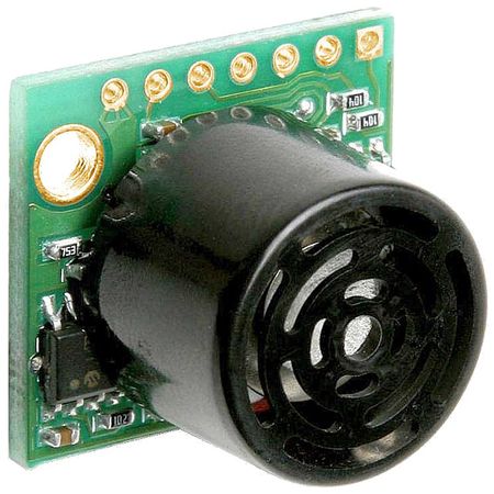
As the capstone project for this class, we designed, prototyped, implemented, and tested an autonomous RC car. Our RC car platform of choice was built by Traxxas as it has a great reputation for building durable RC chassis. On this chassis, we mounted ultrasonic sensors to detect objects surrounding the car and allow it to steer clear of them, a GPS and compass unit that can output important GPS coordinates and heading, a bluetooth module that communicated these location and orientation data to the SJ2 boards, a pair of optical encoders that can detect the car's speed and direction of acceleration, and an LCD screen that provides some important real-time metrics for our debugging purposes. In addition to this debugging method, we also used the provided PCAN dongle to observe CANBus readings and confirm that we were seeing expected values transmitted. Finally, our development of the project was test-driven, using unit tests to confirm the functionality of some code prior to its usage on the car. The rest of this report will detail more specifics about the methodology behind the development of each module.
Introduction
The project was divided into 5 modules:
- Sensor
- Motor
- Geo Controller
- Driver/LCD Controller
- Web application
Team Members & Responsibilities
<Team Picture>
Gitlab Project Link - [1]
- Sensors
- Motor
- Geographical (GPS & compass)
- Driver/Master Controller & LCD
- All of us
- Communication Bridge Controller
- Android Application
Schedule
| Week | Start Date | End Date | Task | Person in Charge (PIC) | Status |
|---|---|---|---|---|---|
| 1 | Feb 27, 2021 | March 5, 2021 | First team meetup to discuss the direction of the project, reviewed past projects and report our findings/concerns | All | Complete |
| 2 | March 6, 2021 | March 13, 2021 | Divide the tasks & responsibilities among the team | All | Complete |
| 3 | March 14, 2021 | March 21, 2021 | Finalize / Buy Parts | All | Complete |
| 3 | March 14, 2021 | March 21, 2021 | Delegate Tasks | All | Complete |
| 3 | March 14, 2021 | March 21, 2021 | Get Data from Ultrasonic Sensor | Eishan, David | Complete |
| 3 | March 14, 2021 | March 21, 2021 | Get Data from Infrared Sensor | Eishan, David | Complete |
| 3 | March 14, 2021 | March 21, 2021 | Initial Draft for common DBC file for sensor readings | Eishan, David | Complete |
| 3 | March 14, 2021 | March 21, 2021 | Get Data from GPS & CMPS14 | Suryanto, Ka | Complete |
| 3 | March 14, 2021 | March 21, 2021 | Develop Bluetooth Driver (UART + customized line buffer) | Tyler | Complete |
| 4 | March 21, 2021 | March 28, 2021 | Initial UI Setup for Mobile App | Tyler | Complete |
| 4 | March 21, 2021 | March 28, 2021 | Bluetooth "Hello World" | Tyler | Complete |
| 4 | March 21, 2021 | March 28, 2021 | Build Driver Controller To Control Motor | Suryanto, Ka | Complete |
| 4 | March 21, 2021 | March 28, 2021 | Disassembly RC Car and Evaluation of Components | Manas | Complete |
| 4 | March 21, 2021 | March 28, 2021 | Complete Motor Drive Development with basic PID control. | Manas | Complete |
| 5 | March 21, 2021 | March 28, 2021 | Implement Bluetooth on Motor for wireless debugging | Manas | Complete |
| 5 | March 28, 2021 | April 04, 2021 | Master Controller Integration | All | Complete |
| 5 | March 28, 2021 | April 04, 2021 | Send Heading / Bearing / Distance info over CANBus to the Driver Node | Suryanto, Ka | Complete |
| 5 | March 28, 2021 | April 04, 2021 | Display Compass, GPS, Steering angle, and Acceleration info on the LCD screen. | Manas, Suryanto | Complete |
| 5 | March 28, 2021 | April 04, 2021 | Research and implement power solution for powering SJ2 boards w/ peripherals | Eishan, Tyler | Complete |
| 5 | March 28, 2021 | April 04, 2021 | Design and Order PCB. | Eishan, Ka, Suryanto | Complete |
| 6 | April 04, 2021 | April 11, 2021 | Map PWM Duty Cycles to real speed (KmPH) readings. | Manas | Complete |
| 6 | April 04, 2021 | April 11, 2021 | Design, 3D print, and assemble LED ring. | Tyler | Complete |
| 6 | April 04, 2021 | April 11, 2021 | Complete required elements of mobile application | Tyler | Complete |
| 6 | April 04, 2021 | April 11, 2021 | Deploy webpage to web server | Tyler | Complete |
| 6 | April 04, 2021 | April 11, 2021 | MIA handling for GPS module | Suryanto, Ka | Complete |
| 6 | April 04, 2021 | April 11, 2021 | Test LED ring which shows the compass info | Suryanto, Ka | Complete |
| 7 | April 11, 2021 | April 18, 2021 | Create Collision Avoidance Algorithm Module | Suryanto, Ka | Complete |
| 7 | April 11, 2021 | April 18, 2021 | Create Pathing from GPS Data | Suryanto, Ka | Delayed |
| 7 | April 11, 2021 | April 18, 2021 | Hardware Integration Test and First Field Test | All | Complete |
| 7 | April 11, 2021 | April 18, 2021 | Optimize Obstacle Detection Based On First Field Test Result (if needed) | Suryanto, Ka | Complete |
| 8 | April 18, 2021 | April 25, 2021 | Design and Print Mounting Components | Tyler | Complete |
| 9 | April 25, 2021 | May 02, 2021 | PCAN / BusMaster Configuration on car. | All | Complete |
| 10 | May 02, 2021 | May 09, 2021 | CANBus Integration | All | Complete |
| 11 | May 09, 2021 | May 16, 2021 | MIA Integration | All | Complete |
| 12 | May 16, 2021 | May 23, 2021 | Big Integration and Live Field Test (Split into 2) | All | In Progress |
| 12 | May 16, 2021 | May 23, 2021 | System Debug & fine tuning | All | In Progress |
| 13 | May 23, 2021 | May 28, 2021 | Demo Prep | All | In Progress |
| 13 | May 23, 2021 | May 28, 2021 | Wiki Report | All | In Progress |
Parts List & Cost
| Item # | Part Description | Vendor | Quantity | Total Cost |
|---|---|---|---|---|
| 1 | GPS Breakout board | Adafruit | 1 | $39.75 |
| 2 | GPS Antenna | Amazon | 1 | $8.43 |
| 3 | CMPS14 | RobotShop | 1 | $35.31 |
| 4 | HC05 | Amazon | 1 | $13.59 |
| 5 | CAN Transceiver | Waveshare | 5 | $21.45 |
| 6 | Infrared sensor(s) | Amazon | 1 | $10.89 |
| 7 | Ultrasonic sensor(s) | Amazon | 3 | $81.78 |
| 8 | SJTwo Evaluation Board | Amazon | 6 | $330 |
| 9 | Traxxas Rustler | Traxxas | 1 | $169.99 |
| 10 | Traxxas Battery + Charger | Traxxas | 1 | $59.99 |
| 11 | High Capacity Battery | Traxxas | 1 | $69.99 |
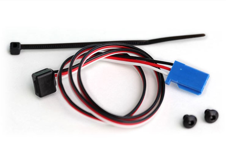
| 12 | RPM sensor | Traxxas | 1 | $12.00 |
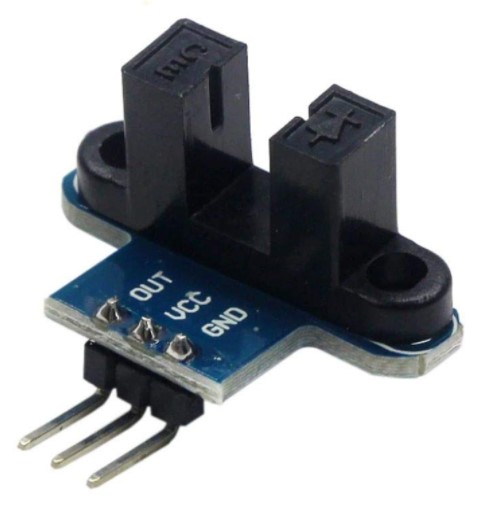
| 13 | Optical Wheel Encoder | Amazon | 1 | $6.99 |
| 14 | LED ring 8 LEDs (Cat shape) | DIY | 1 | N/A |
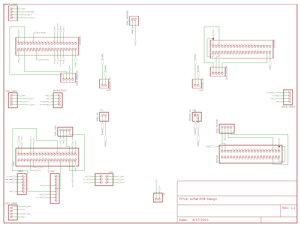
Printed Circuit Board
CAN Communication
<Talk about your message IDs or communication strategy, such as periodic transmission, MIA management etc.>
Hardware Design
<Show your CAN bus hardware design>
DBC File
In our DBC file, we have 6 nodes, DRIVER, SENSOR, BRIDGE, GEO CONTROLLER, COMPASS, and MOTOR. Each of them represents a message sends from one node to another via the CAN bus.
1. The DRIVER sends the throttle and wheel angle command to the MOTOR so it knows when to speed up, speed down and turn.
2. The SENSOR sends the information about how far away is each of the Ultrasonic sensors away from the obstacles
3. The BRIDGE sends the GPS destination to the GEO Controller
4. The GEO CONTROLLER sends the current location of the car back to the BRIDGE
5. The GEO CONTROLLER sends the heading, bearing, and the distance from the destination to the DRIVER
6. The MOTOR sends the PWM and current speed information to the DEBUG node.
Gitlab link to the dbc file
VERSION "1.0.0"

BU_: DRIVER SENSOR BRIDGE GEO_CONTROLLER COMPASS MOTOR

BO_ 100 DRIVER: 3 DRIVER
SG_ DRIVER_throttle : 0|16@1- (0.1,-11) [-11.1|11.1] "kph" MOTOR
SG_ DRIVER_wheel_angle: 16|8@1- (1,-4) [-4|4] "degree" MOTOR

BO_ 200 SENSOR: 5 SENSOR
 SG_ SENSOR_sonar_front_left : 0|10@1+ (1,0) [0|0] "cm" DRIVER
 SG_ SENSOR_sonar_front_mid : 10|10@1+ (1,0) [0|0] "cm" DRIVER
 SG_ SENSOR_sonar_front_right : 20|10@1+ (1,0) [0|0] "cm" DRIVER
 SG_ SENSOR_infrared_back_mid : 30|10@1+ (1,0) [0|0] "cm" DRIVER

BO_ 205 GPS_DESTINATION: 7 BRIDGE
 SG_ LATITUDE_DEGREE : 0|8@1- (1, -90) [-90|90] "degree" GEO_CONTROLLER
 SG_ LONGITUDE_DEGREE : 8|9@1- (1, -180) [-180|180] "degree" GEO_CONTROLLER
 SG_ LATITUDE_MINUTE : 17|6@1+ (1, 0) [0|60] "minute" GEO_CONTROLLER
 SG_ LONGITUDE_MINUTE : 23|6@1+ (1, 0) [0|60] "minute" GEO_CONTROLLER
 SG_ LATITUDE_SECOND : 29|13@1+ (0.01, 0) [0|60] "second" GEO_CONTROLLER
 SG_ LONGITUDE_SECOND : 42|13@1+ (0.01, 0) [0|60] "second" GEO_CONTROLLER

BO_ 206 GPS_CURRENT_LOCATION: 7 GEO_CONTROLLER
 SG_ LATITUDE_DEGREE : 0|8@1- (1, -90) [-90|90] "degree" BRIDGE
 SG_ LONGITUDE_DEGREE : 8|9@1- (1, -180) [-180|180] "degree" BRIDGE
 SG_ LATITUDE_MINUTE : 17|6@1+ (1, 0) [0|60] "minute" BRIDGE
 SG_ LONGITUDE_MINUTE : 23|6@1+ (1, 0) [0|60] "minute" BRIDGE
 SG_ LATITUDE_SECOND : 29|13@1+ (0.01, 0) [0|60] "second" BRIDGE
 SG_ LONGITUDE_SECOND : 42|13@1+ (0.01, 0) [0|60] "second" BRIDGE

BO_ 210 COMPASS_HEADING_DISTANCE: 8 COMPASS
 SG_ HEADING : 0|12@1+ (0.1, 0) [0|359.9] "degrees" DRIVER
 SG_ BEARING : 12|12@1+ (0.1, 0) [0|359.9] "degrees" DRIVER
 SG_ DISTANCE : 24|12@1+ (0.01, 0) [0|0] "meters" DRIVER

BO_ 220 MOTOR_DEBUG: 8 MOTOR
 SG_ MOTOR_PWM : 0|32@1+ (0.01, 0) [10|20] "duty cycle" DEBUG
 SG_ CURRENT_SPEED : 32|32@1- (0.1,-11) [-11.1|11.1] "kph" DEBUG
Sensor ECU
<Picture and link to Gitlab>
Hardware Design
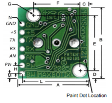
|
Software Design
<List the code modules that are being called periodically.>
Technical Challenges
< List of problems and their detailed resolutions>
Motor ECU
Hardware Design
The hardware portion of the motor controller required the most precision. Because we needed to detect wheel RPM to calculate the speed of the car, we resorted initially to using a Hall Effect sensor and bracket sold by Traxxas. After conducting advanced field testing with this setup, we found out that the magnet's position on the bracket that attached it to the drive gear affected the readings output by the Hall Effect sensor. Sometimes, if the magnet was in the perfect position to trigger the Hall Effect sensor, the car would detect it was moving, though it was stationary. To get the car moving, we usually had to bump it forwards to move the magnet's position; as expected however, this solution is not robust since in the sensor's normal use case, the user would be using a wirelessly transmitting remote to control the car's movement.
To rectify this minor roadblock, we decided to switch to a set of optical wheel encoders. These would allow the same RPM detection as done by the Hall Effect sensor, but without the issue of the car detecting its own movement whilst at a standstill. Additionally, we were able to use a second wheel encoder in conjunction with the first so that we could also detect reverse motion.
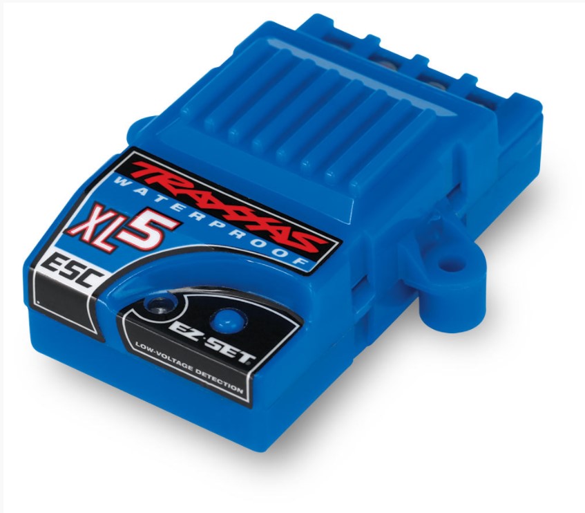
With wheel RPM detection complete, we moved onto integrating wheel speed into the PWM duty cycle applied to the ESC. Our car came equipped with the XL-5 ESC from Traxxas, and it has a very narrow range of PWM values dictating forwards, backwards, and neutral movement.
Since the XL-5 is intended to be controlled by a wireless transmitter, it doesn't have any documentation that helped us integrate with it using our SJ2 boards. So, through some experimentation, we were able to discern a few things about its behavior:
   1. PWM values of 15.0 - 20.0 move the car forward.
   2. PWM values of 10.0 - 14.9 move the car backward.
   3. To begin moving backward or apply "brakes" to the car, the ESC must be issued a reverse signal, then a neutral signal, and then your target PWM value.
      This is to prevent the ESC from causing any significant harm to the motor as well as the clutch that modulates left - to - right wheel speed.
After we knew how to control the ESC to control the drive motor, we applied the same methodology to the servo motor that turns the front wheels. As our car was RWD only, we didn't need to worry about front wheel speeds. Here's what we noticed about the servo motor and the car's turning behavior:
   1. PWM values of 15.0 - 20.0 turn the front wheels right.
   2. PWM values of 10.0 - 14.9 turn the front wheels left.
   3. The car needs some calibration to the front wheels using the TRIM knob on the wireless remote it came with so that it can run straight.
   4. Once the car is loaded with the weight of the boards, peripherals, and battery packs, the front wheels experience a lot of camber and toe angle changes.
      This causes an issue with the alignment previously set with TRIM knob and the car will likely pull in one direction. With some basic hand tools, this
      can be rectified by adjusting the car's camber and toe angle adjustments such that the car will pull straighter. Tightening the front wheels correctly
      is important for these adjustments to work correctly.
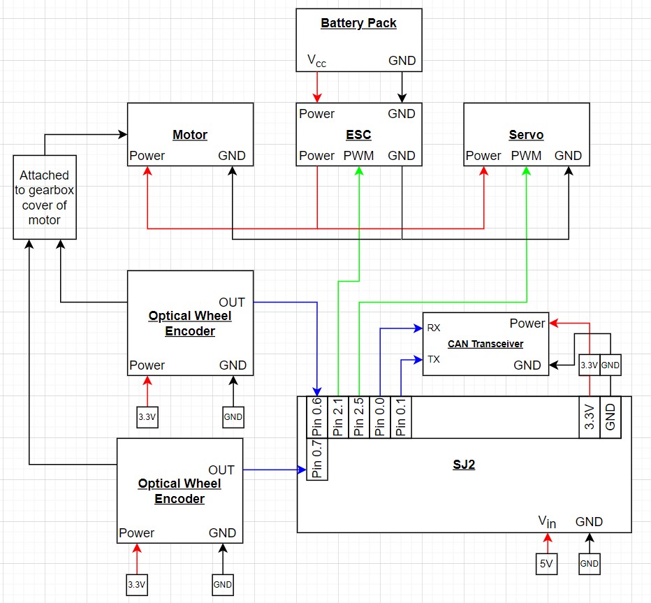
With ESC and servo control figured out, as well as the optical encoder setup to detect wheel RPM, we integrated them all together with the SJ2 Motor Controller board and made the necessary electrical connections. The schematic below shows how our hardware is connected.
Software Design
<List the code modules that are being called periodically.>
Technical Challenges
- The first problem we ran into was controlling the ESC. As mentioned before, the XL-5 was intended to be controlled by a wireless transmitter, and thus doesn't have any documentation available online. When we were testing what PWM values would work, we eventually ran PWM duty cycle sweeps from 0% to 100% to determine what the minimum and maximum thresholds for movement were.
- The second problem we faced was motor acceleration tuning. Before we decided to make use of a PID loop to control the speed of the motor, we often dealt with long wind-up times before the motor began moving. Additionally, when the car needed to slow down, it would slow down too quickly and we would run into a loop of long wind-up times followed by fast deceleration. Our PID loop solved this issue by making the necessary calculations from the car's RPM and current speed and adjusting the PWM value more predictably.
- The final problem we faced was ESC calibration, though this issue was minor. Occasionally, the XL-5 ESC can fall out of calibration, and requires manual calibration to ensure correct operation. This calibration normally has to be done with the wireless transmitter and remote, but we managed to perform the same procedures using an SJ2 board, with its onboard buttons serving to issue PWM values as the ESC needed for calibration.
Geographical Controller
Hardware Design
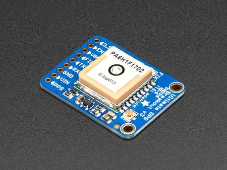
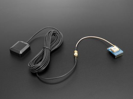
We used the Ultimate GPS Breakout v3 and an antenna to better receive the GPS signal.
For the GPS module, it sends several NMEA sentences but we only look for the $GPGGA ones. Therefore, we had to change the settings of the modules using a USB to UART bridge to send the command to the GPS module.
|
Software Design
<List the code modules that are being called periodically.>
void periodic_callbacks__10Hz(uint32_t callback_count) {

  // receive desintation coordinates from the web app (sensor/bridge controller)
  gps__receive_message(can1);

  gps__run_once();

  // transmit current gps coordinates to the web app (sensor/bridge controller)
  gps__transmit_msg_to_bridge(can1);

  // transmit compass heading, bearing, distance to the driver (driver controller)
  cmps14__transmit_message(can1);

  led_ring_turn_on_led_north();

  count = gps_fix_led_logic(gpio_input_p2_0, gpio_output_p1_18, count);
}
Technical Challenges
< List of problems and their detailed resolutions>
/*** TEMPORARY NOTES ***/
1. Encountered issues with getting fixed coordinates. Fixed it by obtaining external antenna and plugging in CR1220 as a backup battery.
2. The dbc format can support up to only 6 decimal point, which is not accurate when it is being used to store the GPS coordinates. Fix by using the Degrees Minutes Seconds format.
/***********************/
Communication Bridge Controller & LCD
<Picture and link to Gitlab>
Hardware Design
Software Design
<List the code modules that are being called periodically.>
Technical Challenges
< List of problems and their detailed resolutions>
Master Module
<Picture and link to Gitlab>
Hardware Design
Software Design
<List the code modules that are being called periodically.>
Technical Challenges
< List of problems and their detailed resolutions>
Mobile Application
<Picture and link to Gitlab>
Hardware Design
Software Design
<List the code modules that are being called periodically.>
Technical Challenges
< List of problems and their detailed resolutions>
Conclusion
<Organized summary of the project>
<What did you learn?>
Project Video
Project Source Code
Our source code is on Gitlab.
Advise for Future Students
<Bullet points and discussion>
