S21: exFAT
Contents
Project Title
exFAT project title here.
Abstract
Add a few sentence abstract here.
Introduction
The project was divided into 5 modules:
- Sensor
- Motor
- Geo Controller
- Driver/LCD Controller
- Web application
Team Members & Responsibilities
<Team Picture>
Gitlab Project Link - [1]
- Sensors
- Motor
- Geographical (GPS & compass)
- Driver/Master Controller & LCD
- All of us
- Communication Bridge Controller
- Android Application
Schedule
| Week | Start Date | End Date | Task | Person in Charge (PIC) | Status |
|---|---|---|---|---|---|
| 1 | Feb 27, 2021 | March 5, 2021 | First team meetup to discuss the direction of the project, reviewed past projects and report our findings/concerns | All | Complete |
| 2 | March 6, 2021 | March 13, 2021 | Divide the tasks & responsibilities among the team | All | Complete |
| 3 | March 14, 2021 | March 21, 2021 | Finalize / Buy Parts | All | Complete |
| 3 | March 14, 2021 | March 21, 2021 | Delegate Tasks | All | Complete |
| 3 | March 14, 2021 | March 21, 2021 | Get Data from Ultrasonic Sensor | Eishan, David | Complete |
| 3 | March 14, 2021 | March 21, 2021 | Get Data from Infrared Sensor | Eishan, David | Delayed |
| 3 | March 14, 2021 | March 21, 2021 | Initial Draft for common DBC file for sensor readings | Eishan, David | Complete |
| 3 | March 14, 2021 | March 21, 2021 | Get Data from GPS & CMPS14 | Suryanto, Ka | Complete |
| 3 | March 14, 2021 | March 21, 2021 | Develop Bluetooth Driver (UART + customized line buffer) | Tyler | Complete |
| 4 | March 21, 2021 | March 28, 2021 | Initial UI Setup for Mobile App | Tyler | Complete |
| 4 | March 21, 2021 | March 28, 2021 | Bluetooth "Hello World" | Tyler | Complete |
| 4 | March 21, 2021 | March 28, 2021 | Build Driver Controller To Control Motor | Suryanto, Ka | Complete |
| 4 | March 21, 2021 | March 28, 2021 | Disassembly RC Car and Evaluation of Components | Manas | Complete |
| 4 | March 21, 2021 | March 28, 2021 | Complete Motor Drive Development with basic PID control. | Manas | Complete |
| 5 | March 21, 2021 | March 28, 2021 | Implement Bluetooth on Motor for wireless debugging | Manas | Complete |
| 5 | March 28, 2021 | April 04, 2021 | Master Controller Integration | All | Delayed |
| 5 | March 28, 2021 | April 04, 2021 | Send Heading / Bearing / Distance info over CANBus to the Driver Node | Suryanto, Ka | Complete |
| 5 | March 28, 2021 | April 04, 2021 | Display Compass, GPS, Steering angle, and Acceleration info on the LCD screen. | Manas, Suryanto | Delayed |
| 5 | March 28, 2021 | April 04, 2021 | Research and implement power solution for powering SJ2 boards w/ peripherals | Eishan, Tyler | Delayed |
| 5 | March 28, 2021 | April 04, 2021 | Design and Order PCB. | Eishan, Ka, Suryanto | Delayed |
| 6 | April 04, 2021 | April 11, 2021 | Map PWM Duty Cycles to real speed (KmPH) readings. | Manas | Delayed |
| 6 | April 04, 2021 | April 11, 2021 | Design, 3D print, and assemble LED ring. | Tyler | Complete |
| 6 | April 04, 2021 | April 11, 2021 | Complete required elements of mobile application | Tyler | Complete |
| 6 | April 04, 2021 | April 11, 2021 | Deploy webpage to web server | Tyler | Complete |
| 6 | April 04, 2021 | April 11, 2021 | MIA handling for GPS module | Suryanto, Ka | Complete |
| 6 | April 04, 2021 | April 11, 2021 | Test LED ring which shows the compass info | Suryanto, Ka | Complete |
| 7 | April 11, 2021 | April 18, 2021 | Create Collision Avoidance Algorithm Module | Suryanto, Ka | Complete |
| 7 | April 11, 2021 | April 18, 2021 | Create Pathing from GPS Data | Suryanto, Ka | In Progress |
| 7 | April 11, 2021 | April 18, 2021 | Hardware Integration Test and First Field Test | All | In Progress |
| 7 | April 11, 2021 | April 18, 2021 | Optimize Obstacle Detection Based On First Field Test Result (if needed) | Suryanto, Ka | In Progress |
| 8 | April 18, 2021 | April 25, 2021 | Design and Print Mounting Components | TBD | In Progress |
| 9 | April 25, 2021 | May 02, 2021 | PCAN / BusMaster Configuration on car. | All | In Progress |
| 10 | May 02, 2021 | May 09, 2021 | CANBus Integration | All | In Progress |
| 11 | May 09, 2021 | May 16, 2021 | MIA Integration | All | In Progress |
| 12 | May 16, 2021 | May 23, 2021 | Big Integration and Live Field Test (Split into 2) | All | In Progress |
| 12 | May 16, 2021 | May 23, 2021 | System Debug & fine tuning | All | In Progress |
| 13 | May 23, 2021 | May 28, 2021 | Demo Prep | All | In Progress |
| 13 | May 23, 2021 | May 28, 2021 | Wiki Report | All | In Progress |
Parts List & Cost
| Item # | Part Description | Vendor | Quantity | Total Cost |
|---|---|---|---|---|
| 1 | GPS Breakout board | Adafruit | 1 | $39.75 |
| 2 | GPS Antenna | Amazon | 1 | $8.43 |
| 3 | CMPS14 | RobotShop | 1 | $35.31 |
| 4 | HC05 | Amazon | 1 | $13.59 |
| 5 | CAN Transceiver | Waveshare | 5 | $21.45 |
| 6 | Infrared sensor(s) | Amazon | 1 | $10.89 |
| 7 | Ultrasonic sensor(s) | Amazon | 3 | $81.78 |
| 8 | SJTwo Evaluation Board | Amazon | 6 | $330 |
| 9 | Traxxas Rustler | Traxxas | 1 | $169.99 |
| 10 | Traxxas Battery + Charger | Traxxas | 1 | $59.99 |
| 11 | RPM sensor | Traxxas | 1 | $12.00 |
| 12 | LED ring 8 LEDs (Cat shape) | DIY | 1 | N/A |
Printed Circuit Board
<Picture and information, including links to your PCB>
CAN Communication
<Talk about your message IDs or communication strategy, such as periodic transmission, MIA management etc.>
Hardware Design
<Show your CAN bus hardware design>
DBC File
In our DBC file, we have 6 nodes, DRIVER, SENSOR, BRIDGE, GEO CONTROLLER, COMPASS, and MOTOR. Each of them represents a message sends from one node to another via the CAN bus.
1. The DRIVER sends the throttle and wheel angle command to the MOTOR so it knows when to speed up, speed down and turn.
2. The SENSOR sends the information about how far away is each of the Ultrasonic sensors away from the obstacles
3. The BRIDGE sends the GPS destination to the GEO Controller
4. The GEO CONTROLLER sends the current location of the car back to the BRIDGE
5. The GEO CONTROLLER sends the heading, bearing, and the distance from the destination to the DRIVER
6. The MOTOR sends the PWM and current speed information to the DEBUG node.
Gitlab link to the dbc file
VERSION "1.0.0"

BU_: DRIVER SENSOR BRIDGE GEO_CONTROLLER COMPASS MOTOR

BO_ 100 DRIVER: 3 DRIVER
SG_ DRIVER_throttle : 0|16@1- (0.1,-11) [-11.1|11.1] "kph" MOTOR
SG_ DRIVER_wheel_angle: 16|8@1- (1,-4) [-4|4] "degree" MOTOR

BO_ 200 SENSOR: 5 SENSOR
 SG_ SENSOR_sonar_front_left : 0|10@1+ (1,0) [0|0] "cm" DRIVER
 SG_ SENSOR_sonar_front_mid : 10|10@1+ (1,0) [0|0] "cm" DRIVER
 SG_ SENSOR_sonar_front_right : 20|10@1+ (1,0) [0|0] "cm" DRIVER
 SG_ SENSOR_infrared_back_mid : 30|10@1+ (1,0) [0|0] "cm" DRIVER

BO_ 205 GPS_DESTINATION: 7 BRIDGE
 SG_ LATITUDE_DEGREE : 0|8@1- (1, -90) [-90|90] "degree" GEO_CONTROLLER
 SG_ LONGITUDE_DEGREE : 8|9@1- (1, -180) [-180|180] "degree" GEO_CONTROLLER
 SG_ LATITUDE_MINUTE : 17|6@1+ (1, 0) [0|60] "minute" GEO_CONTROLLER
 SG_ LONGITUDE_MINUTE : 23|6@1+ (1, 0) [0|60] "minute" GEO_CONTROLLER
 SG_ LATITUDE_SECOND : 29|13@1+ (0.01, 0) [0|60] "second" GEO_CONTROLLER
 SG_ LONGITUDE_SECOND : 42|13@1+ (0.01, 0) [0|60] "second" GEO_CONTROLLER

BO_ 206 GPS_CURRENT_LOCATION: 7 GEO_CONTROLLER
 SG_ LATITUDE_DEGREE : 0|8@1- (1, -90) [-90|90] "degree" BRIDGE
 SG_ LONGITUDE_DEGREE : 8|9@1- (1, -180) [-180|180] "degree" BRIDGE
 SG_ LATITUDE_MINUTE : 17|6@1+ (1, 0) [0|60] "minute" BRIDGE
 SG_ LONGITUDE_MINUTE : 23|6@1+ (1, 0) [0|60] "minute" BRIDGE
 SG_ LATITUDE_SECOND : 29|13@1+ (0.01, 0) [0|60] "second" BRIDGE
 SG_ LONGITUDE_SECOND : 42|13@1+ (0.01, 0) [0|60] "second" BRIDGE

BO_ 210 COMPASS_HEADING_DISTANCE: 8 COMPASS
 SG_ HEADING : 0|12@1+ (0.1, 0) [0|359.9] "degrees" DRIVER
 SG_ BEARING : 12|12@1+ (0.1, 0) [0|359.9] "degrees" DRIVER
 SG_ DISTANCE : 24|12@1+ (0.01, 0) [0|0] "meters" DRIVER

BO_ 220 MOTOR_DEBUG: 8 MOTOR
 SG_ MOTOR_PWM : 0|32@1+ (0.01, 0) [10|20] "duty cycle" DEBUG
 SG_ CURRENT_SPEED : 32|32@1- (0.1,-11) [-11.1|11.1] "kph" DEBUG
Sensor ECU
<Picture and link to Gitlab>
Hardware Design
Software Design
<List the code modules that are being called periodically.>
Technical Challenges
< List of problems and their detailed resolutions>
Motor ECU
<Picture and link to Gitlab>
Hardware Design
Software Design
<List the code modules that are being called periodically.>
Technical Challenges
< List of problems and their detailed resolutions>
Geographical Controller
Hardware Design
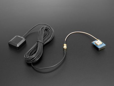
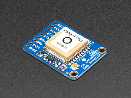
We used the Ultimate GPS Breakout v3 and an antenna to better receive the GPS signal.
For the GPS module, it sends several NMEA sentences but we only look for the $GPGGA ones. Therefore, we had to change the settings of the modules using a USB to UART bridge to send the command to the GPS module.

|
Software Design
<List the code modules that are being called periodically.>
void periodic_callbacks__10Hz(uint32_t callback_count) {

  // receive desintation coordinates from the web app (sensor/bridge controller)
  gps__receive_message(can1);

  gps__run_once();

  // transmit current gps coordinates to the web app (sensor/bridge controller)
  gps__transmit_msg_to_bridge(can1);

  // transmit compass heading, bearing, distance to the driver (driver controller)
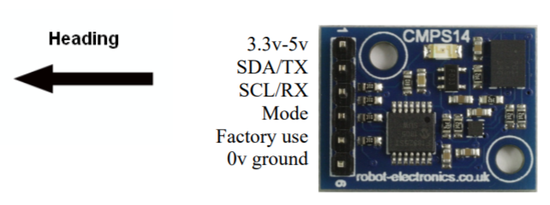
  cmps14__transmit_message(can1);

  led_ring_turn_on_led_north();

  count = gps_fix_led_logic(gpio_input_p2_0, gpio_output_p1_18, count);
}
Technical Challenges
< List of problems and their detailed resolutions>
/*** TEMPORARY NOTES ***/
1. Encountered issues with getting fixed coordinates. Fixed it by obtaining external antenna and plugging in CR1220 as a backup battery.
2. The dbc format can support up to only 6 decimal point, which is not accurate when it is being used to store the GPS coordinates. Fix by using the Degrees Minutes Seconds format.
/***********************/
Communication Bridge Controller & LCD
<Picture and link to Gitlab>
Hardware Design
Software Design
<List the code modules that are being called periodically.>
Technical Challenges
< List of problems and their detailed resolutions>
Master Module
<Picture and link to Gitlab>
Hardware Design
Software Design
<List the code modules that are being called periodically.>
Technical Challenges
< List of problems and their detailed resolutions>
Mobile Application
<Picture and link to Gitlab>
Hardware Design
Software Design
<List the code modules that are being called periodically.>
Technical Challenges
< List of problems and their detailed resolutions>
Conclusion
<Organized summary of the project>
<What did you learn?>
Project Video
Project Source Code
Advise for Future Students
<Bullet points and discussion>

