F20: Son of a Gun
Contents
Abstract
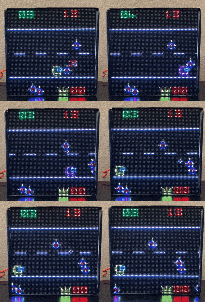
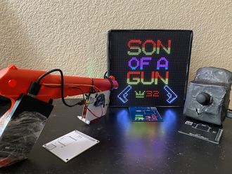
Son Of A Gun is a shooting game inspired by the evergreen classics Duck Hunt and Virtua Cop 2. There will be enemy and friend objects on the LED matrix. The player will use a gun(having IR/color sensor or gyroscope) to aim and shoot the objects on the LED matrix. Killing the friend object will lead to 'Game Over'.
Objectives & Introduction
Show list of your objectives. This section includes the high level details of your project. You can write about the various sensors or peripherals you used to get your project completed.
Team Members & Responsibilities
- Tejas Pidkalwar
- Tirth Pandya
- Nimit Patel
Schedule
| Week# | Date | Task | Actual | Status |
|---|---|---|---|---|
| 1 |
09/23 - 09/29 |
|
|
|
| 2 |
09/30 - 10/06 |
|
|
|
| 3 |
10/07 - 10/13 |
|
|
|
| 4 |
10/14 - 10/20 |
|
|
|
| 5-7 |
10/21 - 11/10 |
|
|
|
| 8 |
11/11 - 11/17 |
|
|
|
| 9 |
11/18 - 11/24 |
|
|
|
| 10 |
11/25 - 12/1 |
|
|
Completed |
| 11 |
12/2- 12/8 |
|
|
Completed |
| 12 |
12/9 - 12/16 |
|
|
Completed |
Parts List & Cost
General Parts
| Item # | Part | Vendor | Qty | Cost |
|---|---|---|---|---|
| 1 | 64x64 RGB LED Matrix | Sparkfun | 1 | $87.15 |
| 2 | SJTwo Boards | Amazon/SJSU | 3 | $150.00 |
| 3 | Zigbee Transreceiver | Amazon | 3 | $88.14 |
| 4 | Zigbee Adapter | Amazon | 1 | $14.16 |
| 5 | Two Axis Joystick | Amazon | 1 | $4.25 |
| 6 | 5V DC Power Supply | Amazon | 1 | $7.58 |
| 7 | MP3 Player | Amazon | 1 | $8.05 |
| 8 | Nintendo Gun | Amazon | 1 | $13.08 |
| 9 | PCB to Order | JLPCB | 3 | $27.03 |
| 10 | Miscellaneous | Excess Solution | 1 | $10.00 |
Design & Implementation
The design section can go over your hardware and software design. Organize this section using sub-sections that go over your design and implementation.
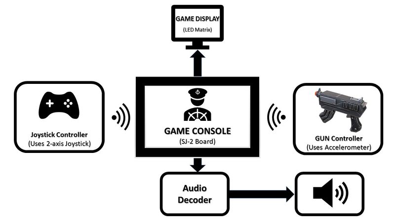
Son of A Gun project is designed using C language, FreeRTOS OS, LPC4078 based SJ-2 board, Zigbee transceivers, joystick, SJ-2's onboard accelerometer. To enclose hardware together we designed PCBs for each module viz Game Console, Joystick controller, and Gun controller.
Hardware Design
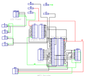
Discuss your hardware design here. Show detailed schematics, and the interface here.
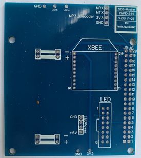
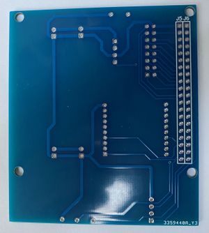
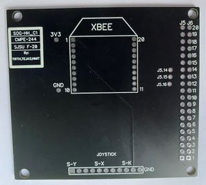
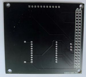
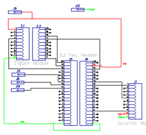
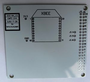
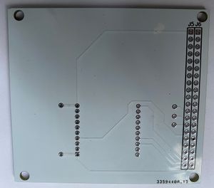
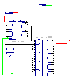
SOG game has 3 modules communicating wirelessly over Zigbee. Each module is controlled by an SJ-2 board and its onboard peripherals. We designed PCBs to enclose each module in a compact and elegant way and placed and a printing order on JLCPCB's portal. JLCPCB delivered printed PCB in 3-4 days.
1) Game Console's PCB:
2) Joystick Controller's PCB:
3) Gun Controller's PCB:
Hardware Interface
In this section, you can describe how your hardware communicates, such as which BUSes used. You can discuss your driver implementation here, such that the Software Design section is isolated to talk about high level workings rather than inner working of your project.
Software Design
Show your software design. For example, if you are designing an MP3 Player, show the tasks that you are using, and what they are doing at a high level. Do not show the details of the code. For example, do not show exact code, but you may show psuedocode and fragments of code. Keep in mind that you are showing DESIGN of your software, not the inner workings of it.
LED Matrix Driver and Graphics algorithm
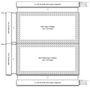
SOG project uses a 64x64 LED matrix by Sparkfun for gameplay graphics display. Each LED pixel can be controlled individually and can operate with 8 colors. To operate the LED matrix, we can select 2 rows at a time, each from 2 planes. Planes are made by dividing 64 rows into 2 halves, i.e. first 32 rows in plane 1 and the remaining 32 rows in plane 2. Five signals (viz. A, B, C, D, and E) which are connected to 5 GPIOs of the SJ-2 board are used to select rows from each plane. R1, G1, B1 signals with 64-bit registers are used to address individual led from the selected row in plane 1. Similarly, R2, G2, B2 signals used to address individual led from the selected row in plane 2. A single clock is interfaced to these 6 64bit shift registers. Hence, at one clock signal, we fill and enable a column corresponding to two selected rows. Once the clocking and register shifting is done, the data need to be latched to the register which in turn enables the corresponding LED.
Our approach to the software design involved the use of eight different tasks for the various moving elements of our gameplay. Seven of these tasks are dedicated to updating the matrix buffer of size 32x64 which is just a two-dimensional array holding the R2, G2, B2 and R1, G1, B1 values. The ninth task has the highest priority which is used to refresh the display. This task gets the latest values from the matrix buffer and is used to display a frame of the game on the LED Matrix display. The matrix buffer is constantly updated in real-time by the other seven tasks such as:
- Title Screen:
- Used to initially display the title screen
- Display the current high score
- Life Display:
- Displays the number of life with friend function
- When health runs out, suspends all other tasks and displays end screen (Game Over)
- Move Friend:
- Move friend object depending on the inputs received from the 2-axis joystick over Zigbee
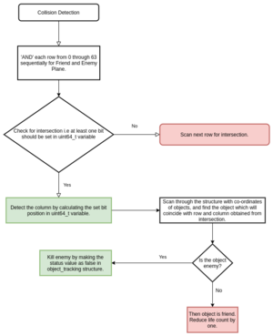
- Collision detection between the Friend and Enemy object.
- On overlap, reduce life by 1
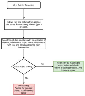
- Detect Gunshot
- Move cursor based on the accelerometer value received over Zigbee
- When the trigger is pressed, verify the object in Friend and Enemy Plane
- If object detected, track which object is detected along with its nature i.e. Friend or Enemy
- Take appropriate action. Reduce Life or kill enemy object and increase score.
- If missed shot then do nothing.
The last task is the refresh display task mentioned above. This task includes a display function that controls the Latch, Clock, Output Enable pins of the LED Matrix display. This function reads the matrix buffer and extracts the R2, G2, B2, R1, G1, B1 values using shift operators.
Implementation
This section includes implementation, but again, not the details, just the high level. For example, you can list the steps it takes to communicate over a sensor, or the steps needed to write a page of memory onto SPI Flash. You can include sub-sections for each of your component implementations.
1. The game involves the use of two controllers: one with a 2-axis joystick and the other with an onboard accelerometer. Apart from that, there is an MP3 decoder that is interfaced over UART.
2. The interfacing of 2 axis joystick is fairly easy. 2 ADCs and the job is done. For accelerometers too, getting values over I2C is a relatively easy task. The challenge to calibrate the motion of the aim cursor with the accelerometer indeed took some efforts to simulate a gun pointer. For the MP3 decoder, there are several MP3 files for various events such as a background theme song, gunshot, level-up sound effect, game-over sound effect etc. All these MP3 files were needed to be modified and the UART commands were synchronized with the corresponding events.
3. Challenge lies in using the Zigbee, with low latency. The serial was initially used, however, was later abandoned and SPI was used for lower latency.
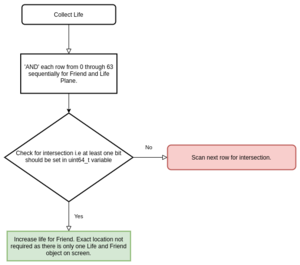
4. Tracking the object onscreen is challenging as the game involves shooting objects. 3 virtual planes are maintained other than the RGB planes, which maintains the greyscale image of objects. Eg: Friend objects are drawn in the friend plane, enemy in the enemy plane, and life objects in the life plane. An intersection of these planes gives the overlap if it exists. Once the intersection is available, the nearest position of the enemy/plane is extracted from the structure and requisite action is taken henceforth.
5. Objects move on the screen on a pseudo-random pattern. The variability of the movement is dependent upon the gave level.
6. Once life becomes over, the game reaches an end.
Testing & Technical Challenges
Describe the challenges of your project. What advise would you give yourself or someone else if your project can be started from scratch again? Make a smooth transition to testing section and described what it took to test your project.
Include sub-sections that list out a problem and solution, such as:
1. Zigbee Drivers: We initially used UART communication(Max possible speed 115200bps)to interface the ZigBee controller to the master controller. With the overhead of size of the frame (21-22 bytes) to send just 2 bytes of data, we observed significantly delayed response at the receiver end. So, we had to change the interface to SPI communication (with a speed of 3 mbps), which being duplex with high speed helped to remove delayed response at the receiver end.
2. Sending button press response over Zigbee: We had implemented GPIO interrupt on GUN controller, which periodically reads accelerometer values and send calibrated values console, and semaphore waiting task to send button press response. The button press was causing occur interrupt to give a semaphore to the button press sender task and was disturbing the RTOS task of calibrating accelerometer values while sending to the game console. To remove this disturbance, we removed the semaphore waiting task on GPIO interrupt and instead used regular accelerometer parameter sender task to send button press signal.
<Bug/issue name>
1. All the objects onscreen are tracked by using a structure file, which has co-ordinates of all the object, their status, shape, and other relevant information. When we call the draw function, the LED worked flawlessly for some time, after which the board would restart. This was because the structure would access out of bound value, which resulted in the board to restart.
2. The object collision algorithm worked only if the object resided on column 32 and above on a 64 x 64 LED panel. On careful observation, it was noticed that the back end function which implemented the collision detection, used bit shifting of uint64 variables. The bits 32 through 63 all had value 0. The bit-shifting part was broken down into two 32 bit shift variables and then these two variables were &-ed together. Though, the comptroller processes all unit64 variable manipulation, the bit shifting one was a surprise and required intricate debugging to get the root cause of the API responding weirdly in an otherwise logical implementation of high-level logic.
Conclusion
Conclude your project here. You can recap your testing and problems. You should address the "so what" part here to indicate what you ultimately learnt from this project. How has this project increased your knowledge?
Project involved using different hardware and then integrating it with the controller to create the game. Creating API for various tasks involved in game flow, helps in modularization of design. This proves especially useful, during debugging, where the problematic API can be easily isolated and this reduces the scope of code review required for each debugging.
Always test the hardware before it is incorporated into your project. however, there might be a case wherein, the API is not available to test the hardware. This become especially tricky, wherein, it becomes difficult to pinpoint issue on either hardware issue or bad code. A fault LED matrix resulted our team in a fortnight worth of time, initially trying to debug the issue, and then waiting for the new part to be shipped to us.
When using wireless data communication modules, latency and packet overhead are important consideration to consider on choosing the best wireless communication module.
Objects which have multiple color, when overlap each other, results in color mixing on LED panel. This needs special attention.
To play multiple MP3 files in synchronization with gameplay is tricky as the MP3 decoder we used doesn't allow to play multiple files simultaneously. Therefore the MP3 files selections and changing the tracks with the gameplay requires some trials and errors approach.
Project Video
Project Source Code
References
Acknowledgement
We would like to thank Professor Preetpal Kang for an innovative course structure where we could learn and test our skills by making innovative games as a project. We were able to enhance our knowledge and put our skills in action while designing the game where we used various embedded devices, communication protocols and technologies.
References Used
- FreeRTOS APIs
- Sparkfun LED Matrix Guide
- LED matrix Driver Guide
- Zigbee Datasheet
- MP3 Decoder Datasheet
Appendix
You can list the references you used.
